Page 1370 of 4133
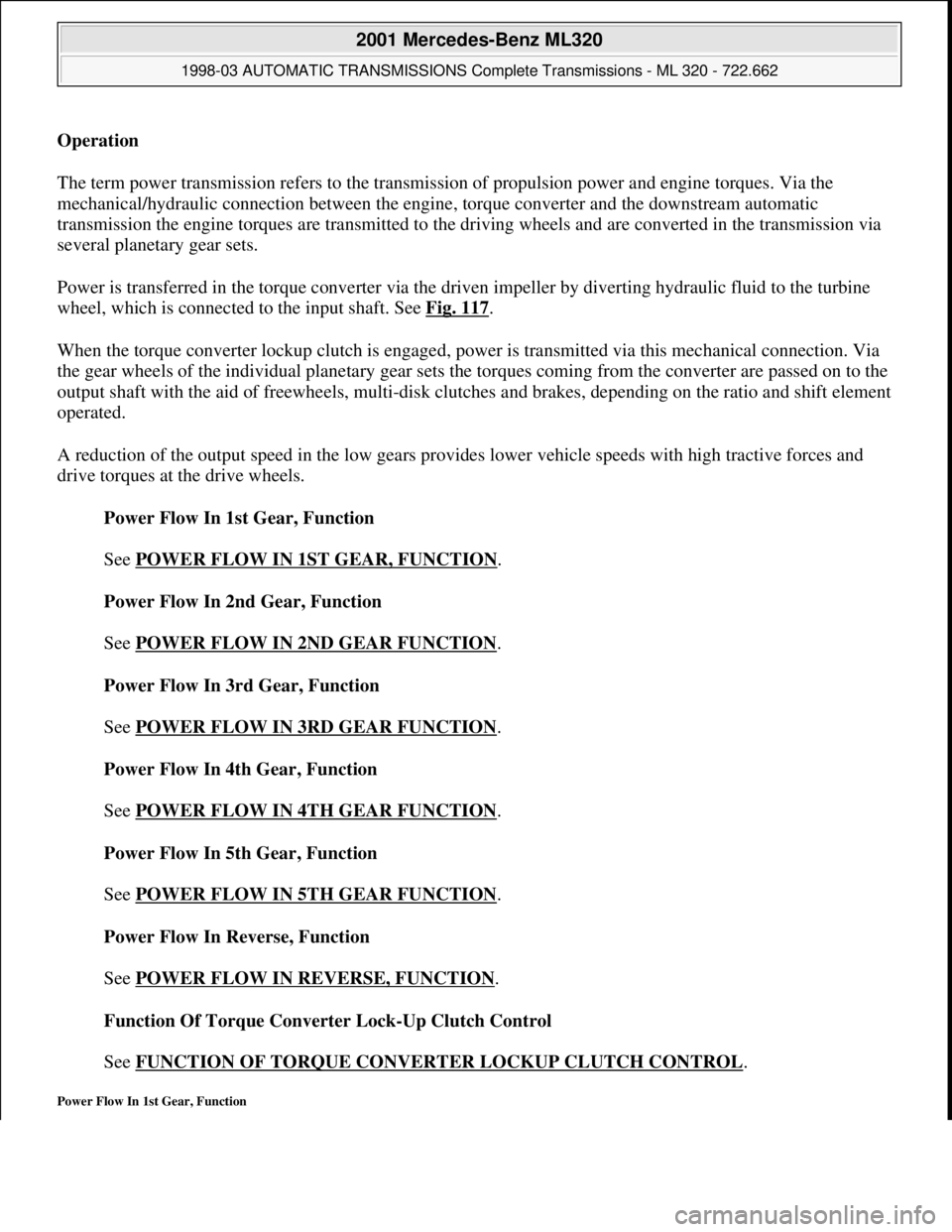
Operation
The term power transmission refers to the transmission of propulsion power and engine torques. Via the
mechanical/hydraulic connection between the engine, torque converter and the downstream automatic
transmission the engine torques are transmitted to the driving wheels and are converted in the transmission via
several planetary gear sets.
Power is transferred in the torque converter via the driven impeller by diverting hydraulic fluid to the turbine
wheel, which is connected to the input shaft. See Fig. 117
.
When the torque converter lockup clutch is engaged, power is transmitted via this mechanical connection. Via
the gear wheels of the individual planetary gear sets the torques coming from the converter are passed on to the
output shaft with the aid of freewheels, multi-disk clutches and brakes, depending on the ratio and shift element
operated.
A reduction of the output speed in the low gears provides lower vehicle speeds with high tractive forces and
drive torques at the drive wheels.
Power Flow In 1st Gear, Function
See POWER FLOW IN 1ST GEAR, FUNCTION
.
Power Flow In 2nd Gear, Function
See POWER FLOW IN 2ND GEAR FUNCTION
.
Power Flow In 3rd Gear, Function
See POWER FLOW IN 3RD GEAR FUNCTION
.
Power Flow In 4th Gear, Function
See POWER FLOW IN 4TH GEAR FUNCTION
.
Power Flow In 5th Gear, Function
See POWER FLOW IN 5TH GEAR FUNCTION
.
Power Flow In Reverse, Function
See POWER FLOW IN REVERSE, FUNCTION
.
Function Of Torque Converter Lock-Up Clutch Control
See FUNCTION OF TORQUE CONVERTER LOCKUP CLUTCH CONTROL
.
Power Flow In 1st Gear, Function
2001 Mercedes-Benz ML320
1998-03 AUTOMATIC TRANSMISSIONS Complete Transmissions - ML 320 - 722.662
me
Saturday, October 02, 2010 3:15:28 PMPage 201 © 2006 Mitchell Repair Information Company, LLC.
Page 1821 of 4133
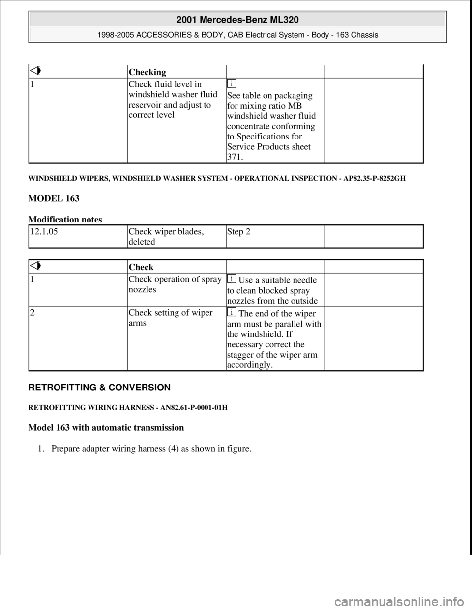
WINDSHIELD WIPERS, WINDSHIELD WASHER SYSTEM - OPERATIONAL INSPECTION - AP82.35-P-8252GH
MODEL 163
Modification notes
RETROFITTING & CONVERSION
RETROFITTING WIRING HARNESS - AN82.61-P-0001-01H
Model 163 with automatic transmission
1. Prepare adapter wirin
g harness (4) as shown in figure.
Checking
1Check fluid level in
windshield washer fluid
reservoir and adjust to
correct level
See table on packaging
for mixing ratio MB
windshield washer fluid
concentrate conforming
to Specifications for
Service Products sheet
371.
12.1.05Check wiper blades,
deletedStep 2
Check
1Check operation of spray
nozzles Use a suitable needle
to clean blocked spray
nozzles from the outside
2Check setting of wiper
arms The end of the wiper
arm must be parallel with
the windshield. If
necessary correct the
stagger of the wiper arm
accordingly.
2001 Mercedes-Benz ML320
1998-2005 ACCESSORIES & BODY, CAB Electrical System - Body - 163 Chassis
me
Saturday, October 02, 2010 3:30:10 PMPage 326 © 2006 Mitchell Repair Information Company, LLC.
Page 2105 of 4133
GF54.30-P-2002A
Display instruments, location / task / function
24.10.96
MODEL
129, 140 as of 1.6.96,
163, 168, 170,
202 as of 1.8.96,
208 up to 31.7.99,
210 as of 1.6.96 up to 30.6.99
Display
Type of data transmission
D
Outside temperature indicator (A1p4)
D
Fuel level gauge (A1p2)
D
Engine oil pressure gauge (A1p3), only
model 129 and model 140
D
Low windshield washer fluid level
indicator lamp (A1e13), model 163 as of
01.09.01
Direct lines
GF54.30-P-3004A
D
Total mileage odometer (A1h4)
D
Electronic speedometer (A1p8)
D
Tachometer (A1p5)
D
Coolant temperature gauge (A1p1)
D
Active service system (ASSYST)
D
Gear indicator (A1p12), only model 168
CAN data lines
GF54.30-P-3005A
D
Electronic clock
Internal
GF54.30-P-3011A
Copyright DaimlerChrysler AG 04.06.2006 CD-Ausgabe G/10/04 . This WIS print-out will not be recorde
d by Modification services.
Page 1
Page 2145 of 4133
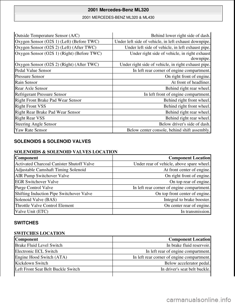
SOLENOIDS & SOLENOID VALVES
SOLENOIDS & SOLENOID VALVES LOCATION
SWITCHES
SWITCHES LOCATION
Outside Temperature Sensor (A/C)Behind lower right side of dash.
Oxygen Sensor (O2S 1) (Left) (Before TWC)Under left side of vehicle, in left exhaust downpipe.
Oxygen Sensor (O2S 2) (Left) (After TWC)Under left side of vehicle, in left exhaust pipe.
Oxygen Sensor (O2S 1) (Right) (Before TWC)Under right side of vehicle, in right exhaust
downpipe.
Oxygen Sensor (O2S 2) (Right) (After TWC)Under right side of vehicle, in right exhaust pipe.
Pedal Value SensorIn left rear corner of engine compartment.
Pressure SensorOn right front of engine.
Rain SensorAt front of headliner.
Rear Axle SensorBehind right rear wheel.
Refrigerant Pressure SensorIn left front of engine compartment.
Right Front Brake Pad Wear SensorBehind right front wheel.
Right Front VSSBehind right front wheel.
Right Rear Brake Pad Wear SensorBehind right rear wheel.
Right Rear VSSBehind right rear wheel.
Steering Angle SensorBelow driver's side of dash.
Yaw Rate SensorBelow center console, behind shift assembly.
ComponentComponent Location
Activated Charcoal Canister Shutoff ValveUnder rear of vehicle, above spare wheel.
Adjustable Camshaft Timing SolenoidAt front center of engine.
AIR Pump Switchover ValveOn right front of engine.
EGR Switchover ValveOn top rear of engine.
Purge Control ValveIn left rear corner of engine compartment.
Shifting Induction Pipe Switchover ValveOn top front center of engine.
Solenoid Valve (BAS)Integral to brake booster.
Throttle Valve Control ElementOn center rear of engine.
Valve Unit (ETC)In transmission.
ComponentComponent Location
Brake Fluid Level SwitchIn brake fluid reservoir.
Electronic ECL SwitchIn left rear of engine compartment.
Engine Hood Switch (ATA)In left rear corner of engine compartment.
Kickdown SwitchBelow accelerator pedal.
Left Front Seat Belt Buckle SwitchIn driver's seat belt buckle.
2001 Mercedes-Benz ML320
2001 MERCEDES-BENZ ML320 & ML430
me
Saturday, October 02, 2010 3:21:17 PMPage 5 © 2006 Mitchell Repair Information Company, LLC.
Page 2524 of 4133
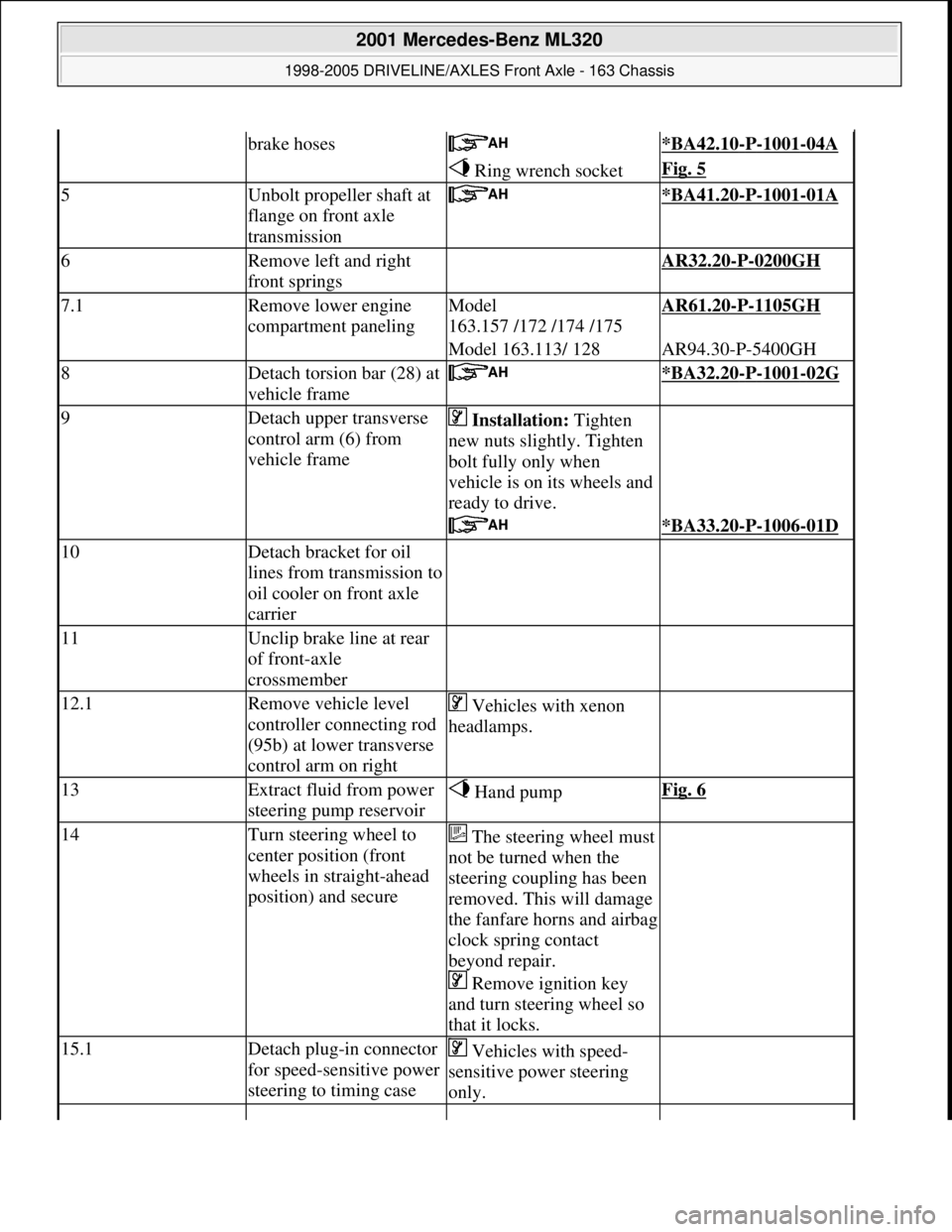
brake hoses *BA42.10-P-1001-04A
Ring wrench socketFig. 5
5Unbolt propeller shaft at
flange on front axle
transmission *BA41.20-P-1001-01A
6Remove left and right
front springs AR32.20-P-0200GH
7.1Remove lower engine
compartment panelingModel
163.157 /172 /174 /175AR61.20-P-1105GH
Model 163.113/ 128AR94.30-P-5400GH
8Detach torsion bar (28) at
vehicle frame *BA32.20-P-1001-02G
9Detach upper transverse
control arm (6) from
vehicle frame Installation: Tighten
new nuts slightly. Tighten
bolt fully only when
vehicle is on its wheels and
ready to drive.
*BA33.20-P-1006-01D
10Detach bracket for oil
lines from transmission to
oil cooler on front axle
carrier
11Unclip brake line at rear
of front-axle
crossmember
12.1Remove vehicle level
controller connecting rod
(95b) at lower transverse
control arm on right Vehicles with xenon
headlamps.
13Extract fluid from power
steering pump reservoir Hand pumpFig. 6
14Turn steering wheel to
center position (front
wheels in straight-ahead
position) and secureThe steering wheel must
not be turned when the
steering coupling has been
removed. This will damage
the fanfare horns and airbag
clock spring contact
beyond repair.
Remove ignition key
and turn steering wheel so
that it locks.
15.1Detach plug-in connector
for speed-sensitive power
steering to timing case Vehicles with speed-
sensitive power steering
only.
2001 Mercedes-Benz ML320
1998-2005 DRIVELINE/AXLES Front Axle - 163 Chassis
me
Saturday, October 02, 2010 3:38:21 PMPage 5 © 2006 Mitchell Repair Information Company, LLC.
Page 2561 of 4133
Fig. 68: Identifying Front Axle Gear Components
Modification notes
8.1.07Filling capacity, Specifications for Operating FluidsModel 163*BF33.30-P-1001-03B
Remove/install
1
Remove front wheels
Remove/install wheels, rotate if
necessaryAP40.10-P-
4050GH
2Drain front axle gear oil
Installation: ?
Check front axle gear oil level and
top up if necessary
Oil drain screw: ?AR33.30-P-
0525-02GH
Oil filler plug: ?*BA33.30-P-
1003-03B
*BA33.30-P-
1002-03B
*BF33.30-P-
1001-03B
3Unbolt propeller shaft at flange on front
axle transmission *BA41.20-P-
1001-01A
4Press both follower joints out of upper
transverse control arms using puller
Check rubber boot and ball joint for
wear and damage.AR33.20-P-
0500-01GH
*BA33.20-P-
1001-01D
2001 Mercedes-Benz ML320
1998-2005 DRIVELINE/AXLES Front Axle - 163 Chassis
me
Saturday, October 02, 2010 3:38:22 PMPage 42 © 2006 Mitchell Repair Information Company, LLC.
Page 2565 of 4133
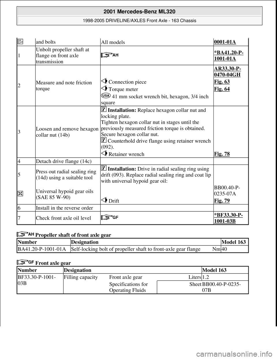
Propeller shaft of front axle gear
Front axle gear
and boltsAll models0001-01A
1
Unbolt propeller shaft at
flange on front axle
transmission
*BA41.20-P-
1001-01A
2Measure and note friction
torque
AR33.30-P-
0470-04GH
Connection pieceFig. 63
Torque meterFig. 64
41 mm socket wrench bit, hexagon, 3/4 inch
square
3Loosen and remove hexagon
collar nut (14b)
Installation: Replace hexagon collar nut and
locking plate.
Tighten hexagon collar nut in stages until the
previously measured friction torque is obtained.
Secure hexagon collar nut.
Counterhold drive flange using retainer wrench
(092).
Retainer wrenchFig. 78
4Detach drive flange (14c)
5Press out radial sealing ring
(14d) using a suitable tool Installation: Drive in radial sealing ring using
drift (093). Replace radial sealing ring and coat lip
with universal hypoid gear oil:
Universal hypoid gear oils
(SAE 85 W-90) BB00.40-P-
0235-07A
DriftFig. 79
6Install in the reverse order
7Check front axle oil level *BF33.30-P-
1001-03B
NumberDesignationModel 163
BA41.20-P-1001-01ASelf-locking bolt of propeller shaft to front-axle gear flangeNm40
NumberDesignationModel 163
BF33.30-P-1001-
03BFilling capacity Front axle gearLiters1.2
Specifications for
Operating FluidsSheetBB00.40-P-0235-
07B
2001 Mercedes-Benz ML320
1998-2005 DRIVELINE/AXLES Front Axle - 163 Chassis
me
Saturday, October 02, 2010 3:38:22 PMPage 46 © 2006 Mitchell Repair Information Company, LLC.
Page 2568 of 4133
Wheel location, hub
Front axle gear
Fig. 82: Identifying Thrust Piece (129 589 10 63 00)
Fig. 83: Identifying Base (163 589 01 43 00)
4Lever front axle shaft out of
front axle transmission Do not damage shield.
5Press out radial shaft sealing
ring (14e) using a suitable tool Installation: Drive in radial shaft seal using
drift (094). Install new radial shaft seal and coat
lip with universal hypoid gear oil.
Universal hypoid gear oils
(SAE 85 W-90) BB00.40-P-
0235-07A
DriftFig. 85
6Install in the reverse order
NumberDesignationModel 163
BA33.20-P-1001-01DSelf-locking nut, upper wishbone foll ower joint to steering knuckleNm50
NumberDesignationModel 163
BF33.30-P-1001-
03BFilling capacityFront axle gearLiters1.2
Specifications for
Operating FluidsSheetBB00.40-P-0235-
07B
2001 Mercedes-Benz ML320
1998-2005 DRIVELINE/AXLES Front Axle - 163 Chassis
me
Saturday, October 02, 2010 3:38:22 PMPage 49 © 2006 Mitchell Repair Information Company, LLC.