1997 MERCEDES-BENZ ML320 seat memory
[x] Cancel search: seat memoryPage 3499 of 4133
AR68.10-P-1040GH
Remove/install bottom section of instrument panel
13.3.97
MODELS
163.113 /128 /136 /154 /157 /172 /174 /175
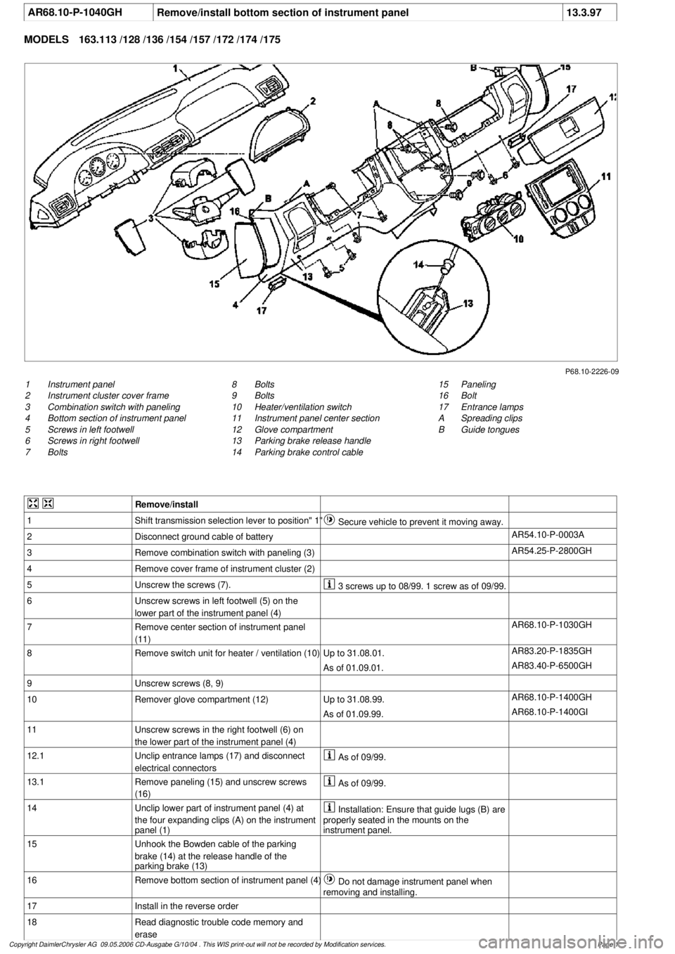
P68.10-2226-09
1
Instrument panel
2
Instrument cluster cover frame
3
Combination switch with paneling
4
Bottom section of instrument panel
5
Screws in left footwell
6
Screws in right footwell
7
Bolts
15
Paneling
16
Bolt
17
Entrance lamps
A
Spreading clips
B
Guide tongues
8
Bolts
9
Bolts
10
Heater/ventilation switch
11
Instrument panel center section
12
Glove compartment
13
Parking brake release handle
14
Parking brake control cable
Remove/install
1
Shift transmission selection lever to position" 1"
Secure vehicle to prevent it moving away.
2
Disconnect ground cable of battery
AR54.10-P-0003A
3
Remove combination switch with paneling (3)
AR54.25-P-2800GH
4
Remove cover frame of instrument cluster (2)
5
Unscrew the screws (7).
3 screws up to 08/99. 1 screw as of 09/99.
6
Unscrew screws in left footwell (5) on the
lower part of the instrument panel (4)
7
Remove center section of instrument panel
(11)
AR68.10-P-1030GH
8
Remove switch unit for heater / ventilation (10)
Up to 31.08.01.
AR83.20-P-1835GH
As of 01.09.01.
AR83.40-P-6500GH
9
Unscrew screws (8, 9)
10
Remover glove compartment (12)
Up to 31.08.99.
AR68.10-P-1400GH
As of 01.09.99.
AR68.10-P-1400GI
11
Unscrew screws in the right footwell (6) on
the lower part of the instrument panel (4)
12.1
Unclip entrance lamps (17) and disconnect
electrical connectors
As of 09/99.
13.1
Remove paneling (15) and unscrew screws
(16)
As of 09/99.
14
Unclip lower part of instrument panel (4) at
the four expanding clips (A) on the instrument
panel (1)
Installation: Ensure that guide lugs (B) are
properly seated in the mounts on the
instrument panel.
15
Unhook the Bowden cable of the parking
brake (14) at the release handle of the
parking brake (13)
16
Remove bottom section of instrument panel (4)
Do not damage instrument panel when
removing and installing.
17
Install in the reverse order
18
Read diagnostic trouble code memory and
erase
Copyright DaimlerChrysler AG 09.05.2006 CD-Ausgabe G/10/04 . This WIS print-out will not be recorde
d by Modification services.
Page 1
Page 3539 of 4133
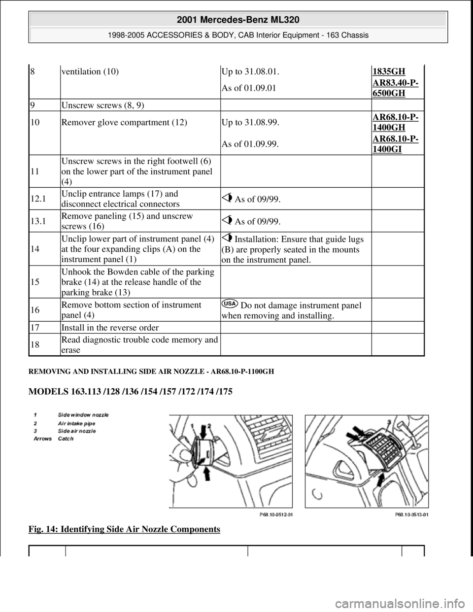
REMOVING AND INSTALLING SIDE AIR NOZZLE - AR68.10-P-1100GH
MODELS 163.113 /128 /136 /154 /157 /172 /174 /175
Fig. 14: Identifying Side Air Nozzle Components
8ventilation (10)Up to 31.08.01.1835GH
As of 01.09.01AR83.40-P-
6500GH
9Unscrew screws (8, 9)
10Remover glove compartment (12)Up to 31.08.99.AR68.10-P-
1400GH
As of 01.09.99.AR68.10-P-
1400GI
11
Unscrew screws in the right footwell (6)
on the lower part of the instrument panel
(4)
12.1Unclip entrance lamps (17) and
disconnect electrical connectors As of 09/99.
13.1Remove paneling (15) and unscrew
screws (16) As of 09/99.
14
Unclip lower part of instrument panel (4)
at the four expanding clips (A) on the
instrument panel (1) Installation: Ensure that guide lugs
(B) are properly seated in the mounts
on the instrument panel.
15
Unhook the Bowden cable of the parking
brake (14) at the release handle of the
parking brake (13)
16Remove bottom section of instrument
panel (4) Do not damage instrument panel
when removing and installing.
17Install in the reverse order
18Read diagnostic trouble code memory and
erase
2001 Mercedes-Benz ML320
1998-2005 ACCESSORIES & BODY, CAB Interior Equipment - 163 Chassis
me
Saturday, October 02, 2010 3:35:21 PMPage 21 © 2006 Mitchell Repair Information Company, LLC.
Page 3789 of 4133
AR91.29-P-0008GH
Remove/install seat adjustment control module
23.6.99
MODEL
163.113 /128,
163.136 /154 as of 1.9.99,
163.157,
163.172 as of 1.9.99,
163.175
with CODE (241) Memory for electrically adjustable left front seat
with CODE (242a) Memory for electrically adjustable right front seat
MODEL
163.174
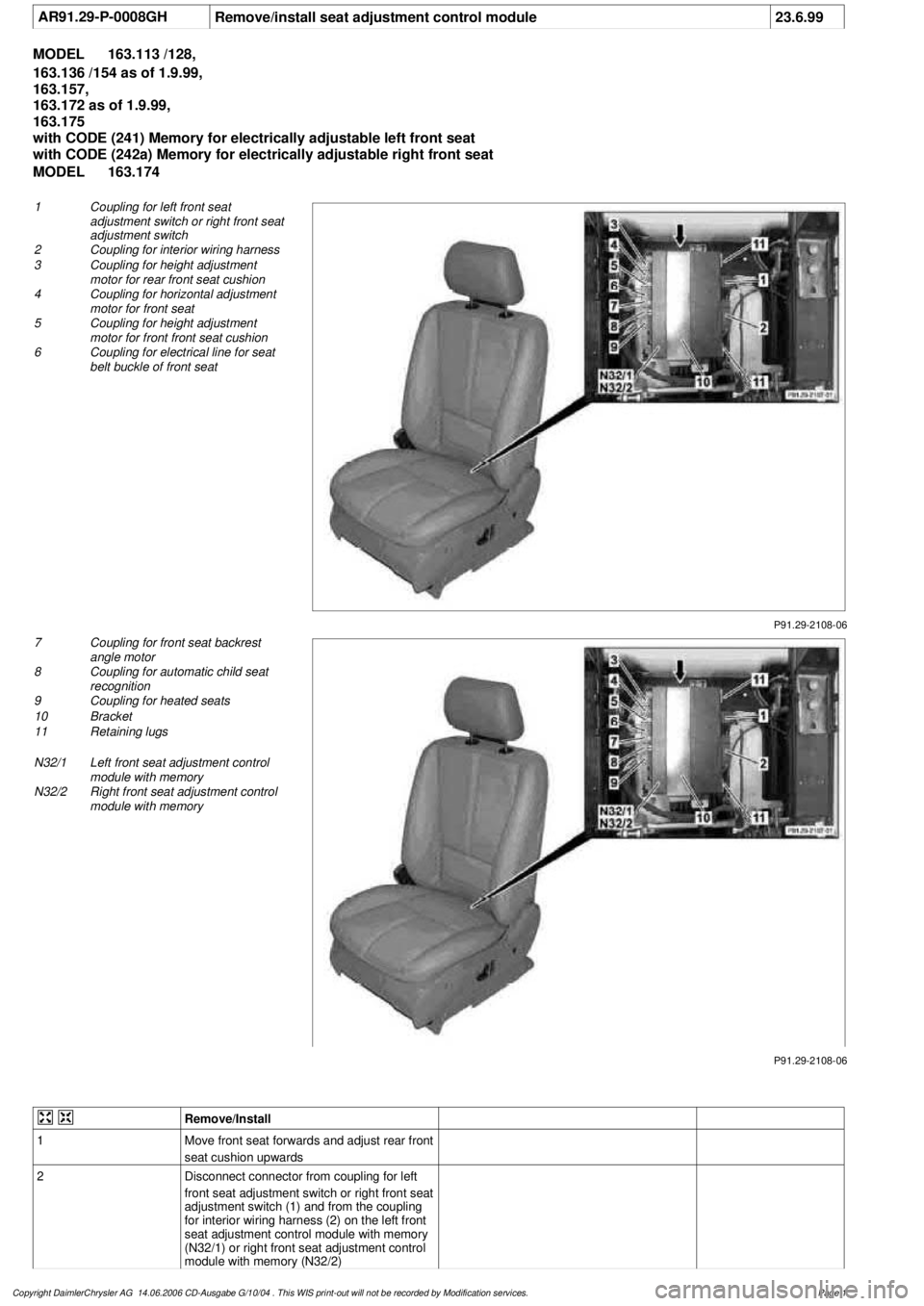
P91.29-2108-06
1
Coupling for left front seat
adjustment switch or right front seat
adjustment switch
2
Coupling for interior wiring harness
3
Coupling for height adjustment
motor for rear front seat cushion
4
Coupling for horizontal adjustment
motor for front seat
5
Coupling for height adjustment
motor for front front seat cushion
6
Coupling for electrical line for seat
belt buckle of front seat
P91.29-2108-06
7
Coupling for front seat backrest
angle motor
8
Coupling for automatic child seat
recognition
9
Coupling for heated seats
10
Bracket
11
Retaining lugs
N32/1
Left front seat adjustment control
module with memory
N32/2
Right front seat adjustment control
module with memory
Remove/Install
1
Move front seat forwards and adjust rear front
seat cushion upwards
2
Disconnect connector from coupling for left
front seat adjustment switch or right front seat
adjustment switch (1) and from the coupling
for interior wiring harness (2) on the left front
seat adjustment control module with memory
(N32/1) or right front seat adjustment control
module with memory (N32/2)
Copyright DaimlerChrysler AG 14.06.2006 CD-Ausgabe G/10/04 . This WIS print-out will not be recorde
d by Modification services.
Page 1
Page 3790 of 4133

3
Unscrew bolt (arrow) from bracket (10),
unhook front bracket and remove
4
Remove left front seat adjustment control
module with memory (N32/1) or right front
seat adjustment control module with memory
(N32/2) from bracket on front seat frame
Unhook two retaining lugs (11) on the side.
5
Disconnect the remaining connectors on the
left front seat adjustment control module with
memory (N32/1) or right front seat adjustment
control module with memory (N32/2)
6
Remove left front seat adjustment control
module with memory (N32/1) or right front
seat adjustment control module with memory
(N32/2)
7
Install in the reverse order
8
Perform function check
Copyright DaimlerChrysler AG 14.06.2006 CD-Ausgabe G/10/04 . This WIS print-out will not be recorde
d by Modification services.
Page 2
Page 3791 of 4133
AR91.29-P-0003GI
Remove/install seat adjustment switch unit on front seat
1.10.02
MODEL
163.113,
163.136 #A as of 051500,
163.136 #X as of 708319,
163.154 #A as of 051500,
163.154 #X as of 708319,
163.157 /172 with CODE (221b) Electrically adjustable driver and passenger seat
MODEL
163.128 /174 /175
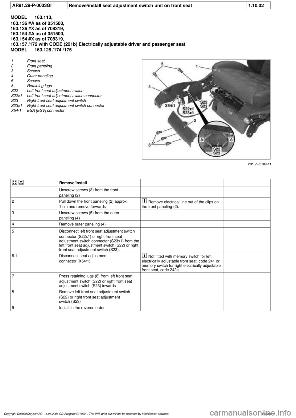
P91.29-2109-11
1
Front seat
2
Front paneling
3
Screws
4
Outer paneling
5
Screws
8
Retaining lugs
S22
Left front seat adjustment switch
S22x1
Left front seat adjustment switch connector
S23
Right front seat adjustment switch
S23x1
Right front seat adjustment switch connector
X54/1
ESA [ESV] connector
Remove/install
1
Unscrew screws (3) from the front
paneling (2)
2
Pull down the front paneling (2) approx.
1 cm and remove forwards
Remove electrical line out of the clips on
the front paneling (2).
3
Unscrew screws (5) from the outer
paneling (4)
4
Remove outer paneling (4)
5
Disconnect left front seat adjustment switch
connector (S22x1) or right front seat
adjustment switch connector (S23x1) from the
left front seat adjustment switch (S22) or right
front seat adjustment switch (S23).
6.1
Disconnect seat adjustment
connector (X54/1)
Not fitted with memory switch for left
electrically adjustable front seat, code 241 or
memory switch for right electrically adjustable
front seat, code 242a.
7
Press retaining lugs (8) from left front seat
adjustment switch (S22) or right front seat
adjustment switch (S23) inwards
8
Remove left front seat adjustment switch
(S22) or right front seat adjustment
switch (S23)
9
Install in the reverse order
Copyright DaimlerChrysler AG 14.06.2006 CD-Ausgabe G/10/04 . This WIS print-out will not be recorde
d by Modification services.
Page 1
Page 3792 of 4133
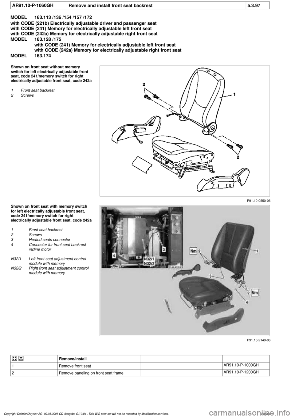
AR91.10-P-1060GH
Remove and install front seat backrest
5.3.97
MODEL
163.113 /136 /154 /157 /172
with CODE (221b) Electrically adjustable driver and passenger seat
with CODE (241) Memory for electrically adjustable left front seat
with CODE (242a) Memory for electrically adjustable right front seat
MODEL
163.128 /175
with CODE (241) Memory for electrically adjustable left front seat
with CODE (242a) Memory for electrically adjustable right front seat
MODEL
163.174
P91.10-0550-06
Shown on front seat without memory
switch for left electrically adjustable front
seat, code 241/memory switch for right
electrically adjustable front seat, code 242a
1
Front seat backrest
2
Screws
P91.10-2149-06
Shown on front seat with memory switch
for left electrically adjustable front seat,
code 241/memory switch for right
electrically adjustable front seat, code 242a
1
Front seat backrest
2
Screws
3
Heated seats connector
4
Connector for front seat backrest
incline motor
N32/1
Left front seat adjustment control
module with memory
N32/2
Right front seat adjustment control
module with memory
Remove/install
1
Remove front seat
AR91.10-P-1000GH
2
Remove paneling on front seat frame
AR91.10-P-1200GH
Copyright DaimlerChrysler AG 09.05.2006 CD-Ausgabe G/10/04 . This WIS print-out will not be recorde
d by Modification services.
Page 1
Page 3793 of 4133

3.1
Disconnect heated seats connector (3) and
connector for front seat backrest incline motor
(4) from left front seat adjustment control
module with memory (N32/1) or right front
seat adjustment control module with memory
(N32/2)
Only for memory switch for left electrically
adjustable front seat, code 241 or memory
switch for right electrically adjustable front
seat, code 242a.
Installation:
Ensure that the electrical
lines are routed properly!
4
Unscrew screws (2) from backrest fittings
*BA91.10-P-1003-01B
Torx bit set
*000589011000
5
Remove front seat backrest (1)
6
Install in the reverse order
Front seats
Number
Designation
Model
Series 163
BA91.10-P-1003-01B
Bolt, front seat backrest to seat frame
Nm
30 (
F
3)
Torx bit set
000 589 01 10 00
Copyright DaimlerChrysler AG 09.05.2006 CD-Ausgabe G/10/04 . This WIS print-out will not be recorde
d by Modification services.
Page 2
Page 3797 of 4133
AR91.10-P-1200GH
Remove/install front seat frame trim
4.3.97
MODEL
163.113 /136 /154 /157 /172 with CODE (221b) Electrically adjustable driver and passenger seat
MODEL
163.128 /174 /175
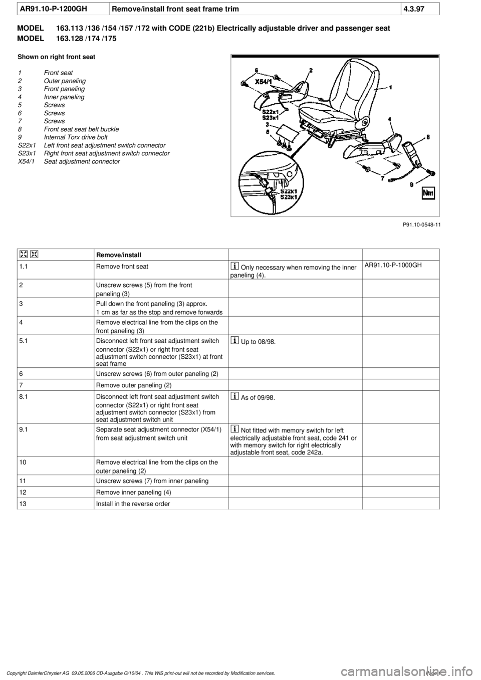
P91.10-0548-11
Shown on right front seat
1
Front seat
2
Outer paneling
3
Front paneling
4
Inner paneling
5
Screws
6
Screws
7
Screws
8
Front seat seat belt buckle
9
Internal Torx drive bolt
S22x1
Left front seat adjustment switch connector
S23x1
Right front seat adjustment switch connector
X54/1
Seat adjustment connector
Remove/install
1.1
Remove front seat
Only necessary when removing the inner
paneling (4).
AR91.10-P-1000GH
2
Unscrew screws (5) from the front
paneling (3)
3
Pull down the front paneling (3) approx.
1 cm as far as the stop and remove forwards
4
Remove electrical line from the clips on the
front paneling (3)
5.1
Disconnect left front seat adjustment switch
connector (S22x1) or right front seat
adjustment switch connector (S23x1) at front
seat frame
Up to 08/98.
6
Unscrew screws (6) from outer paneling (2)
7
Remove outer paneling (2)
8.1
Disconnect left front seat adjustment switch
connector (S22x1) or right front seat
adjustment switch connector (S23x1) from
seat adjustment switch unit
As of 09/98.
9.1
Separate seat adjustment connector (X54/1)
from seat adjustment switch unit
Not fitted with memory switch for left
electrically adjustable front seat, code 241 or
with memory switch for right electrically
adjustable front seat, code 242a.
10
Remove electrical line from the clips on the
outer paneling (2)
11
Unscrew screws (7) from inner paneling
12
Remove inner paneling (4)
13
Install in the reverse order
Copyright DaimlerChrysler AG 09.05.2006 CD-Ausgabe G/10/04 . This WIS print-out will not be recorde
d by Modification services.
Page 1