1997 MERCEDES-BENZ ML320 service reset
[x] Cancel search: service resetPage 2066 of 4133

GF54.30-P-2004A
Control buttons, location/task
24.10.96
MODEL
129, 140 as of 1.6.96,
163, 170
The instrument cluster has two control buttons which are on the left
or right next to the speedometer.
The
right control button
is used to adjust the time (refer to Owner's
Manual).
-----------------------------------------------------------------------------------------
The
left control button
is used
D
to regulate the instrument illumination
D
to activate the display illumination
D
to reset the trip odometer display
D
to operate the maintenance display (model 170 only bis 05.97)
D
to operate the Active Service System ASSYST (as of 06.97)
-----------------------------------------------------------------------------------------
n
Purpose/function of terminal 58d, instrument
display illumination
Engines 112, 113, 611 (engines with oil
sensor)
GF54.30-P-3008A
n
Electronic clock
GF54.30-P-3011A
n
Active Service System (ASSYST)
GF00.20-P-0003-01A
Operating instructions, resetting
Model 210 as of 01.03.97 with engines M111,
OM 602, OM 604, OM 605 and
OM 606
As of 06/97 models 129, 140, 170, 202 except
engines 112, 113, 611
(valid for engines with oil level switch)
GF00.20-P-0003-01B
Copyright DaimlerChrysler AG 05.06.2006 CD-Ausgabe G/10/04 . This WIS print-out will not be recorde
d by Modification services.
Page 1
Page 2079 of 4133

9
Install inner cover (E) at 60 % bench
Insert cover past the springs from the rear
and rotate into position in a clockwise
direction. Insert locating tabs (19). Press the
front cover down and reset so that locating
tabs (20) engage. Press rear cover down until
locating tabs (18) engage.
10
Install outer cover (D) at 60 % bench
Guide the cover past the lateral curtain.
Insert locating tab (17), push front cover down
and reset so that locating tabs (16) engage.
Press the outer edge of the cover down and
insert lateral locating tabs (15). Raise rear
cover on the inside, press down until locating
tab (14) and rear locating tab (13) engage.
11
Install curtain at front 60 % bench
12
Install inner cover (C) at 40 % bench
Insert cover from the front and insert
locating tabs (11). Press the front cover down
and reset so that locating tabs (12) engage.
13
Install outer cover (B) at 40 % bench
Guide the cover past the lateral curtain.
Insert locating tab (10), push front cover down
and reset so that locating tab (9) engages.
Press the outer edge of the cover down and
insert lateral locating tabs (8). Insert locating
tab (7), push cover down at locating tab (6)
and engage.
14
Install curtain at front 40 % bench
15
Install rear cover (A)
Insert cover from the rear and press down
and forwards so that locating tabs (5) engage.
Press front ends of the cover down, so that
locating tabs (2, 3, 4) engage. Insert locating
tabs (1) into covers (C, E).
Copyright DaimlerChrysler AG 28.05.2006 CD-Ausgabe G/10/04 . This WIS print-out will not be recorde
d by Modification services.
Page 2
Page 2236 of 4133

GF00.20-P-2009A
Engine oil monitor function
24.10.96
MODEL
129 with ENGINE 112, 113
MODEL
163 with ENGINE 112, 113, 612
MODEL
168 with ENGINE 166, 668
MODEL
202 with ENGINE 112, 611
MODEL
208 up to 31.7.99 with ENGINE 112, 113
MODEL
210 up to 30.6.99 with ENGINE 112, 113, 611
General
The oil level is constantly monitored by the oil sensor, and the
appropriate data transmitted to the processor by the ASSYST.
Oil replenishments are detected automatically and result in a bonus,
which extends the service interval accordingly.
An excess oil level or insufficient oil level appears in the display
together with the oil can symbol.
Display of low oil level at maximum:
D
at driver request
Display of warnings: D
automatically, at the earliest 60 s after engine start and oil
temperature greater than 60°C:
D
if oil level too high: the oil can symbol appears together
with the readout "OIL LEVEL ABOVE MAX". In addition, a
brief warning signal sounds. (On models not fitted with
multifunction displaly, "HI" appears flashing.)
D
if oil level too low: the oil can symbol appears together with
the readout "OIL LEVEL BELOW MIN". In addition, a brief
warning signal sounds. (On models not fitted with multifunction
display, the oil level warning lamp (A1e12) comes on and the
readout "-2L" appears flashing.)
-----------------------------------------------------------------------------------------
D
if oil at minimum: the oil can symbol appears together with
the readout "OIL LEVEL MINIMUM". In addition, a brief
warning signal sounds. (On models not fitted with multifunction
display, the oil level warning lamp (A1e12) comes on.)
D
automatically 13 s after ignition ON:
D
if
no oil
is in engine: the oil can symbol appears together
with the readout "OIL LEVEL BELOW MIN". In addition, a
warning signal sounds. (On models not fitted with multifunction
display, the oil level warning lamp (A1e12) comes on and the
readout "-2L"appears flashing. In addition a brief warning
signal sounds.)
The missing oil quantity displayed no longer changes during the
display. In other words, any change in oil level cannot be observed
directly at the display. The new oil level is only displayed once the
conditions described below exist.
Display of oil quantity at driver request
The text "DISPLAY OIL LEVEL?" appears 10 s after the start switch
has been turned into position "2" (on models not fitted with
multifunction display, the oil can and the clock symbol are displayed).
If the reset button of the trip counter is pressed twice within one sec.
during this readout, for example, "add 1.0L oil" (or "-1.0L")
-----------------------------------------------------------------------------------------
appears in the display if oil level too low. The readout appears only
after the elapse of a waiting time after engine OFF. The waiting time
depends on the engine oil temperature.
It is
D
up to 20°C
30 minutes
D
from 60°C
1 minute
D
The waiting time is between these two limits at other engine oil
temperatures.
Possible readouts are (text in parenthesis relates to models not fitted
with multifunction display.):
D
"OIL LEVEL OKAY" ("o.k."),
D
1.0L, 1.5L, 2L,
D
"Overfilling" ("HI"),
D
"OBSERVE WAITING TIME" (clock symbol flashing and oil can
symbol),
D
"DISPLAY OIL LEVEL" (clock and oil can symbols.)
If there is a fault at the oil sensor (oil level/temperature/quality, B40)
the oil can symbol and the text "OIL LEVEL SENSOR FAULTY"
appears only 30 s after the fault has occurred.
(On models not fitted with multifunction display, the oil level warning
lamp (A1e12) comes on accordingly.)
For diagnosis, read also the injection system control module (N3)
with the HHT. (The instrument cluster (A1) receives the sensor data
through the CAN from the injection system control module (N3)).
-----------------------------------------------------------------------------------------
Oil change
The ASSYST has to be reset each time the oil is changed. Resetting
ASSYST also resets the remaining time and the remaining distance.
Resetting can be performed at the instrument cluster or using the
HHT.
The following data are stored when the system is reset:
D
current kilometer reading rounded off to 100,
D
total oil replenishments in the last interval,
D
remaining distance,
D
remaining time,
D
product of the quality factors,
D
the data of the last 5 resettings in 5 data sets
These data can only be read with the HHT!
If the specified quantity of oil is not replenished when the oil is
changed, the (internal) start distance is reduced.
Detecting oil replenishments
D
With the
HHT
it is possible to retrieve the last 10 oil
replenishments and the corresponding kilometer readings of
the current interval.
D
In the normal case, detection of an oil replenishment is
displayed by the remaining distance in the instrument cluster
being extended
-----------------------------------------------------------------------------------------
Copyright DaimlerChrysler AG 05.06.2006 CD-Ausgabe G/10/04 . This WIS print-out will not be recorde
d by Modification services.
Page 1
Page 2238 of 4133

P00.20-0202-06
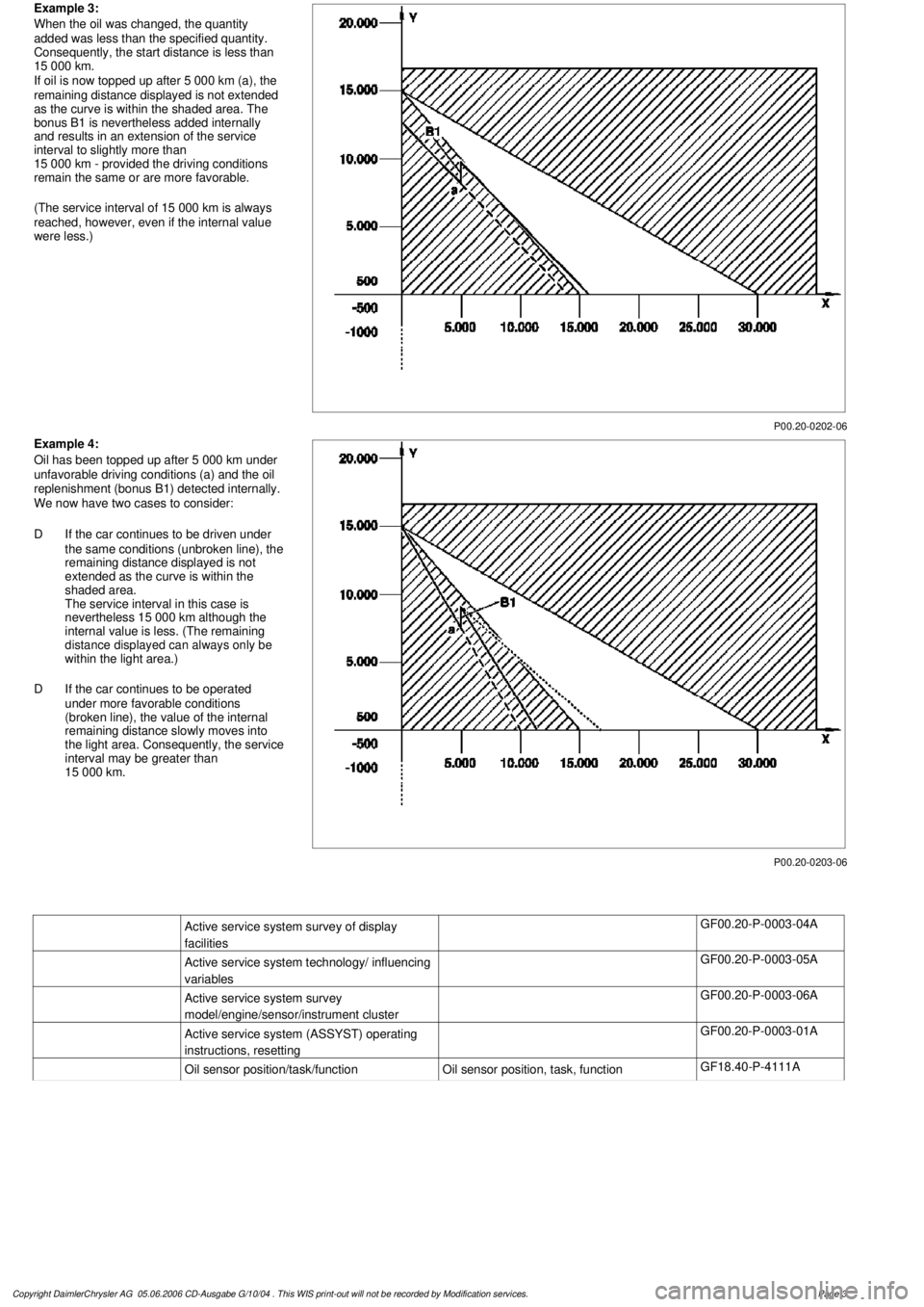
Example 3:
When the oil was changed, the quantity
added was less than the specified quantity.
Consequently, the start distance is less than
15 000 km.
If oil is now topped up after 5 000 km (a), the
remaining distance displayed is not extended
as the curve is within the shaded area. The
bonus B1 is nevertheless added internally
and results in an extension of the service
interval to slightly more than
15 000 km - provided the driving conditions
remain the same or are more favorable.
(The service interval of 15 000 km is always
reached, however, even if the internal value
were less.)
P00.20-0203-06
Example 4:
Oil has been topped up after 5 000 km under
unfavorable driving conditions (a) and the oil
replenishment (bonus B1) detected internally.
We now have two cases to consider:
D
If the car continues to be driven under
the same conditions (unbroken line), the
remaining distance displayed is not
extended as the curve is within the
shaded area.
The service interval in this case is
nevertheless 15 000 km although the
internal value is less. (The remaining
distance displayed can always only be
within the light area.)
D
If the car continues to be operated
under more favorable conditions
(broken line), the value of the internal
remaining distance slowly moves into
the light area. Consequently, the service
interval may be greater than
15 000 km.
Active service system survey of display
facilities
GF00.20-P-0003-04A
Active service system technology/ influencing
variables
GF00.20-P-0003-05A
Active service system survey
model/engine/sensor/instrument cluster
GF00.20-P-0003-06A
Active service system (ASSYST) operating
instructions, resetting
GF00.20-P-0003-01A
Oil sensor position/task/function
Oil sensor position, task, function
GF18.40-P-4111A
Copyright DaimlerChrysler AG 05.06.2006 CD-Ausgabe G/10/04 . This WIS print-out will not be recorde
d by Modification services.
Page 3
Page 2595 of 4133

AF54.30-P-2064A
Fuel gauge not registering correctly after refueling vehicle
4.2.03
MODEL
163.### #A as of 221506 up to 364039,
163.### #X as of 734088 up to 777100
Operation no. of operation texts or standard texts and flat rates
Sector
Op. no.
Operation text
Time
Acc. no.
Code
P
023803
RECODE INSTRUMENT CLUSTER
003 WU/0.3 h
54 208 50
---
Damage Code
Cause
Remedy
Refuel recognition software may not
recognize incremental refueling (< 7 L).
In case of complaint
#
The fuel gauge operation defaults to back-
up mode, and continuously decreases last
stored sensor value based on consumption
data supplied via engine management. This
continues until either refuel recognition or
instrument cluster (A1) reset occurs (via
STAR Diagnosis or power disconnect).
Vehicles with 83 L fuel tank (as of MY2002)
are more susceptible to this condition.
This applies only to instrument clusters
(A1) with diagnostic version 3/05, 3/06,
and 3/07.
1
Connect STAR Diagnosis.
2
Under "Control module adaptations" in
"ICM" menu, set "Fuel tank characteristic
curve" from "Normal" to "Direct sensor
value".
DO NOT replace the instrument cluster
(A1) or fuel pump assembly (M3) for this
condition.
Copyright DaimlerChrysler AG 28.05.2006 CD-Ausgabe G/10/04 . This WIS print-out will not be recorde
d by Modification services.
Page 1
Page 2840 of 4133

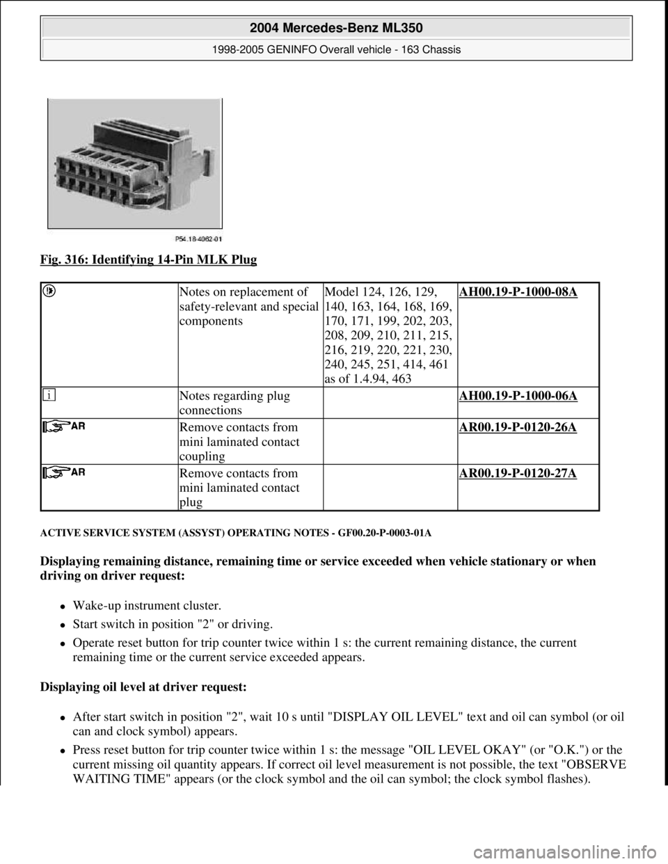
Fig. 316: Identifying 14-Pin MLK Plug
ACTIVE SERVICE SYSTEM (ASSYST) OPERATING NOTES - GF00.20-P-0003-01A
Displaying remaining distance, remaining time or service exceeded when vehicle stationary or when
driving on driver request:
Wake-up instrument cluster.
Start switch in position "2" or driving.
Operate reset button for trip counter twice within 1 s: the current remaining distance, the current
remaining time or the current service exceeded appears.
Displaying oil level at driver request:
After start switch in position "2", wait 10 s until "DISPLAY OIL LEVEL" text and oil can symbol (or oil
can and clock symbol) appears.
Press reset button for trip counter twice within 1 s: the message "OIL LEVEL OKAY" (or "O.K.") or the
current missing oil quantity appears. If correct oil level measurement is not possible, the text "OBSERVE
WAITING TIME" appears (or the clock s
ymbol and the oil can symbol; the clock symbol flashes).
Notes on replacement of
safety-relevant and special
componentsModel 124, 126, 129,
140, 163, 164, 168, 169,
170, 171, 199, 202, 203,
208, 209, 210, 211, 215,
216, 219, 220, 221, 230,
240, 245, 251, 414, 461
as of 1.4.94, 463AH00.19-P-1000-08A
Notes regarding plug
connections AH00.19-P-1000-06A
Remove contacts from
mini laminated contact
coupling AR00.19-P-0120-26A
Remove contacts from
mini laminated contact
plug AR00.19-P-0120-27A
2004 Mercedes-Benz ML350
1998-2005 GENINFO Overall vehicle - 163 Chassis
me
Saturday, October 02, 2010 3:47:47 PMPage 195 © 2006 Mitchell Repair Information Company, LLC.
Page 2841 of 4133

(The texts in parentheses relate to vehicles without multifunction display.)
Resetting ASSYST after oil change (oil change reset) at instrument cluster:
Move start switch into position "2".
Within the first 4 s after moving start switch into position "2": press reset button for trip counter twice
within one second. The display for the servi ce request is thus activated for 10 s.
Within these 10 s move start switch into position "0". The service request continues to be displayed.
Press reset button for trip counter and hold pressed .
Move start switch into position "2".
Continue to hold reset button for trip counter pressed (about 10 s) until the signal sounds and the new
start distance appears in the display.
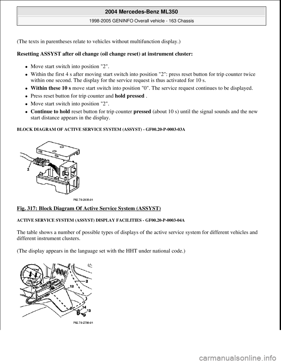
BLOCK DIAGRAM OF ACTI VE SERVICE SYSTEM (ASSYST) - GF00.20-P-0003-03A
Fig. 317: Block Diagram Of Acti ve Service System (ASSYST)
ACTIVE SERVICE SYSTEM (ASSYST) DISPLAY FACILITIES - GF00.20-P-0003-04A
The table shows a number of pos sible types of displays of the active se rvice system for different vehicles and
different instru ment clusters.
(The display appears in the language set with the HHT under national code.)
2004 Mercedes-Benz ML350
1998-2005 GENINFO Overall vehicle - 163 Chassis
me
Saturday, October 02, 2010 3:47:47 PMPage 196 © 2006 Mitchell Repair Information Company, LLC.
Page 2849 of 4133

The figure may differ from this, however, depending on quality factors.
The start distance is automatically reset to its initial value by the oil change reset each time the oil is changed.
The start distance is an internal computed quantity and cannot be displayed in the instrument cluster. It is
possible to display the start distance with the HHT.
What is normally displayed in the instrument cluster is the remaining distance .
The remaining distance is the same as the start distance immediately after the oil change. On engines with oil
sensor (e.g. 112, 113, 166, 611, 668) this applies only, however, if the specified quantity of oil has been added
during the oil change.
The remaining distance is the distance which remains from the current kilometer reading until the next
service. The possible length of the interval is at least as great as the remaining distance displayed
immediately after an oil change, and is at the most twice the start distance.
The remaining distance is dependent on
the start distance
the driving conditions (a weighting of the distance driven takes place)
any oil replenishments in the case of engines with oil sensor (e.g. 112, 113, 166, 611, 668)
Consequently, ASSYST also takes into account the driving conditions: In the case of a favorable weighting
(e.g. small number of cold starts, no high engine revs, small number of short-distance trips, minimum extent of
towing a trailer etc.) and oil replenishments, the driver is provided with a bonus which extends the remaining
distance and thus the service interval. Account is also taken of whether the vehicle is actually driven or whether
the engine runs at idle speed. ASSYST is constantly supplied with the data regarding the current operating
conditions of the vehicle for this purpose.
In the case of the best weighting , only 0.6 km are added for each kilometer driven.
In the case of the most unfavorable weighting of the distance (e.g. frequent short-distance trips, large number
of cold starts), the remaining distance and thus the service interval is smaller than in the case of the most
favorable weighting (assuming identical quality factors).
In the case of the most unfavorable weighting, up to 3 km are added for each kilometer driven.
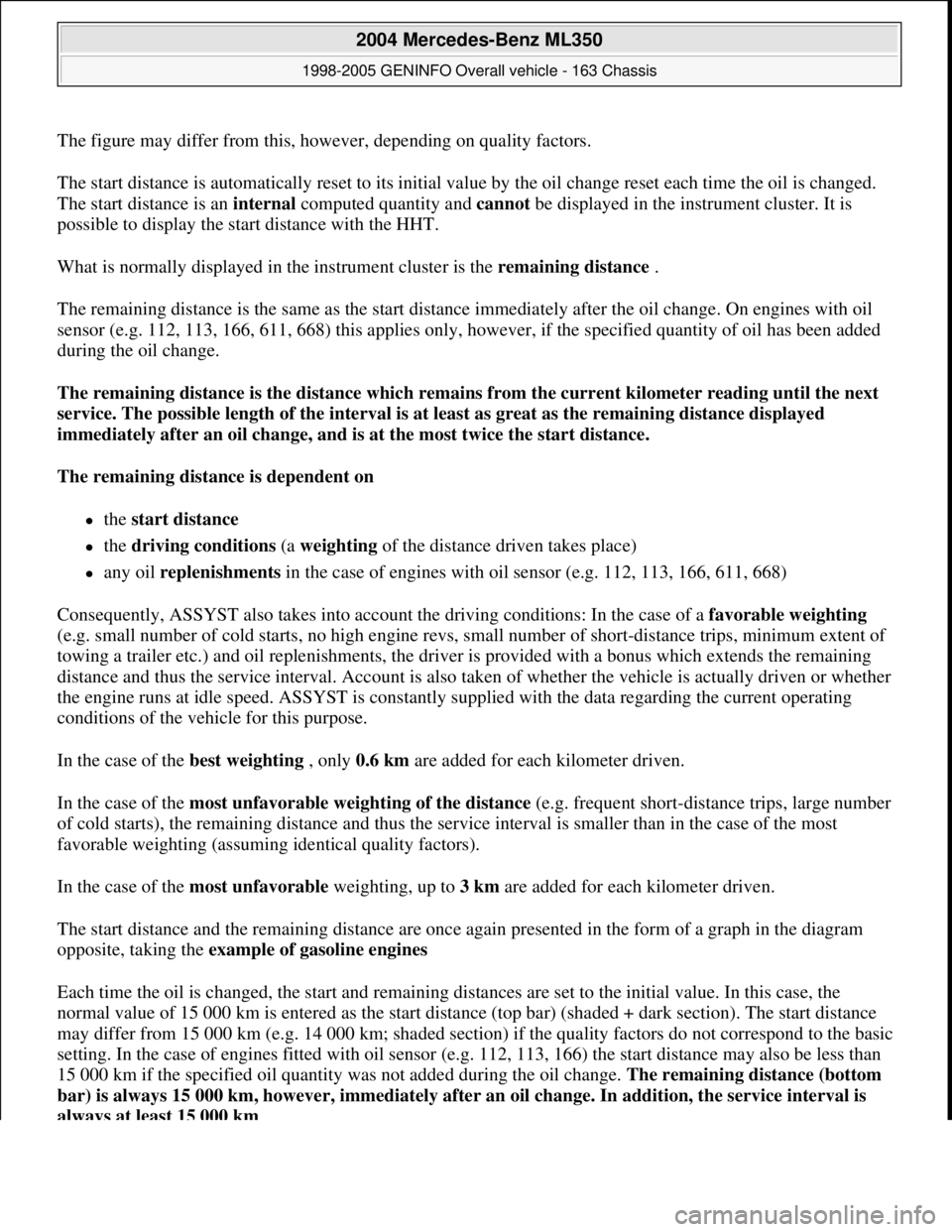
The start distance and the remaining distance are once again presented in the form of a graph in the diagram
opposite, taking the example of gasoline engines
Each time the oil is changed, the start and remaining distances are set to the initial value. In this case, the
normal value of 15 000 km is entered as the start distance (top bar) (shaded + dark section). The start distance
may differ from 15 000 km (e.g. 14 000 km; shaded section) if the quality factors do not correspond to the basic
setting. In the case of engines fitted with oil sensor (e.g. 112, 113, 166) the start distance may also be less than
15 000 km if the specified oil quantity was not added during the oil change. The remaining distance (bottom
bar) is always 15 000 km, however, immediately after an oil change. In addition, the service interval is
always at least 15 000 km .
2004 Mercedes-Benz ML350
1998-2005 GENINFO Overall vehicle - 163 Chassis
me
Saturday, October 02, 2010 3:47:47 PMPage 204 © 2006 Mitchell Repair Information Company, LLC.