1997 MERCEDES-BENZ ML320 check transmission fluid
[x] Cancel search: check transmission fluidPage 1177 of 4133
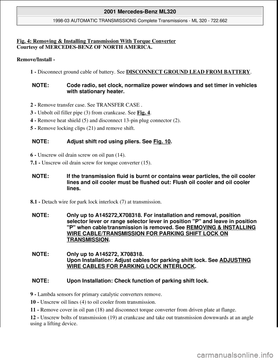
Fig. 4: Removing & Installing Transmission With Torque Converter
Courtesy of MERCEDES-BENZ OF NORTH AMERICA.
Remove/Install -
1 - Disconnect ground cable of battery. See DISCONNECT GROUND LEAD FROM BATTERY
.
2 - Remove transfer case. See TRANSFER CASE .
3 - Unbolt oil filler pipe (3) from crankcase. See Fig. 4
.
4 - Remove heat shield (5) and disconnect 13-pin plug connector (2).
5 - Remove locking clips (21) and remove shift.
6 - Unscrew oil drain screw on oil pan (14).
7.1 - Unscrew oil drain screw for torque converter (15).
8.1 - Detach wire for park lock interlock (7) at transmission.
9 - Lambda sensors for primary catalytic converters remove.
10 - Unscrew oil lines (4) to oil cooler from transmission.
11 - Remove cover in oil pan (18) and disconnect torque converter from driven plate at flange.
12 - Unscrew bolts of transmission (19) at crankcase and take out transmission downwards at an angle
using a lifting device. NOTE: Code radio, set clock, normalize power windows and set timer in vehicles
with stationary heater.
NOTE: Adjust shift rod using pliers. See Fig. 10
.
NOTE: If the transmission fluid is burnt or contains wear particles, the oil cooler
lines and oil cooler must be flushed out: Flush oil cooler and oil cooler
lines.
NOTE: Only up to A145272,X708318. For installation and removal, position
selector lever or range selector lever in position "P" and leave in position
"P" when cable/transmission is removed. See REMOVING & INSTALLING
WIRE CABLE/TRANSMISSION FOR PARKING SHIFT LOCK ON
TRANSMISSION.
NOTE: Only up to A145272, X708318.
Upon Installation: Adjust cables for parking shift lock. See ADJUSTING
WIRE CABLES FOR PARKING LOCK INTERLOCK.
NOTE: Upon Installation: Check function of parking shift lock.
2001 Mercedes-Benz ML320
1998-03 AUTOMATIC TRANSMISSIONS Complete Transmissions - ML 320 - 722.662
me
Saturday, October 02, 2010 3:15:25 PMPage 8 © 2006 Mitchell Repair Information Company, LLC.
Page 1821 of 4133
WINDSHIELD WIPERS, WINDSHIELD WASHER SYSTEM - OPERATIONAL INSPECTION - AP82.35-P-8252GH
MODEL 163
Modification notes
RETROFITTING & CONVERSION
RETROFITTING WIRING HARNESS - AN82.61-P-0001-01H
Model 163 with automatic transmission
1. Prepare adapter wirin
g harness (4) as shown in figure.
Checking
1Check fluid level in
windshield washer fluid
reservoir and adjust to
correct level
See table on packaging
for mixing ratio MB
windshield washer fluid
concentrate conforming
to Specifications for
Service Products sheet
371.
12.1.05Check wiper blades,
deletedStep 2
Check
1Check operation of spray
nozzles Use a suitable needle
to clean blocked spray
nozzles from the outside
2Check setting of wiper
arms The end of the wiper
arm must be parallel with
the windshield. If
necessary correct the
stagger of the wiper arm
accordingly.
2001 Mercedes-Benz ML320
1998-2005 ACCESSORIES & BODY, CAB Electrical System - Body - 163 Chassis
me
Saturday, October 02, 2010 3:30:10 PMPage 326 © 2006 Mitchell Repair Information Company, LLC.
Page 2561 of 4133
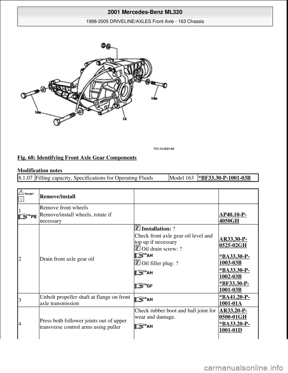
Fig. 68: Identifying Front Axle Gear Components
Modification notes
8.1.07Filling capacity, Specifications for Operating FluidsModel 163*BF33.30-P-1001-03B
Remove/install
1
Remove front wheels
Remove/install wheels, rotate if
necessaryAP40.10-P-
4050GH
2Drain front axle gear oil
Installation: ?
Check front axle gear oil level and
top up if necessary
Oil drain screw: ?AR33.30-P-
0525-02GH
Oil filler plug: ?*BA33.30-P-
1003-03B
*BA33.30-P-
1002-03B
*BF33.30-P-
1001-03B
3Unbolt propeller shaft at flange on front
axle transmission *BA41.20-P-
1001-01A
4Press both follower joints out of upper
transverse control arms using puller
Check rubber boot and ball joint for
wear and damage.AR33.20-P-
0500-01GH
*BA33.20-P-
1001-01D
2001 Mercedes-Benz ML320
1998-2005 DRIVELINE/AXLES Front Axle - 163 Chassis
me
Saturday, October 02, 2010 3:38:22 PMPage 42 © 2006 Mitchell Repair Information Company, LLC.
Page 2565 of 4133
Propeller shaft of front axle gear
Front axle gear
and boltsAll models0001-01A
1
Unbolt propeller shaft at
flange on front axle
transmission
*BA41.20-P-
1001-01A
2Measure and note friction
torque
AR33.30-P-
0470-04GH
Connection pieceFig. 63
Torque meterFig. 64
41 mm socket wrench bit, hexagon, 3/4 inch
square
3Loosen and remove hexagon
collar nut (14b)
Installation: Replace hexagon collar nut and
locking plate.
Tighten hexagon collar nut in stages until the
previously measured friction torque is obtained.
Secure hexagon collar nut.
Counterhold drive flange using retainer wrench
(092).
Retainer wrenchFig. 78
4Detach drive flange (14c)
5Press out radial sealing ring
(14d) using a suitable tool Installation: Drive in radial sealing ring using
drift (093). Replace radial sealing ring and coat lip
with universal hypoid gear oil:
Universal hypoid gear oils
(SAE 85 W-90) BB00.40-P-
0235-07A
DriftFig. 79
6Install in the reverse order
7Check front axle oil level *BF33.30-P-
1001-03B
NumberDesignationModel 163
BA41.20-P-1001-01ASelf-locking bolt of propeller shaft to front-axle gear flangeNm40
NumberDesignationModel 163
BF33.30-P-1001-
03BFilling capacity Front axle gearLiters1.2
Specifications for
Operating FluidsSheetBB00.40-P-0235-
07B
2001 Mercedes-Benz ML320
1998-2005 DRIVELINE/AXLES Front Axle - 163 Chassis
me
Saturday, October 02, 2010 3:38:22 PMPage 46 © 2006 Mitchell Repair Information Company, LLC.
Page 3046 of 4133

For these vehicles the service sheet for the Active Service System (ASSYST) and the maintenance manual
volume 4 apply.
With the ASSYST service sheet the previous distinction between care service and maintenance service no
longer applies. Instead, the service category A (minor service) and service category B (major service) have been
introduced.
The service scopes for each model series can be seen in the respective valid service sheet.
The order no. is stated on the particular SERVICE SHEET.
On manual transmissions, automatic transmissions, transfer cases, front axles and rear axles the service item
"Check fluid level" has been replaced by an inspection of all visible parts for leaks.
In view of the fact that these components are not oil consumers, as is the case for the engine, a loss of oil can
occur only to the outside.
If any leaks are present, the procedure, as before, is to determine the cause and to rectify it subject to a separate
repair order.
The service operations carried out should be documented in the boxes in front of the operation titles. It is
essential to ensure that the specified service operations are carried out in full.
An indication is given in the boxes after the operation titles of which service operations should be carried out
for service category A (minor service) or service category B (major service). Enter a cross behind these boxes to
identify any items which are not in proper order when the vehicle is received.
Additional operations should be defined by the service adviser in agreement with the customer and an indication
should be made on the service sheet whether these additional operations are to be carried out.
Fig. 642: Service Intervals/Work Sheets
2004 Mercedes-Benz ML350
1998-2005 GENINFO Overall vehicle - 163 Chassis
me
Saturday, October 02, 2010 3:47:52 PMPage 401 © 2006 Mitchell Repair Information Company, LLC.
Page 3049 of 4133
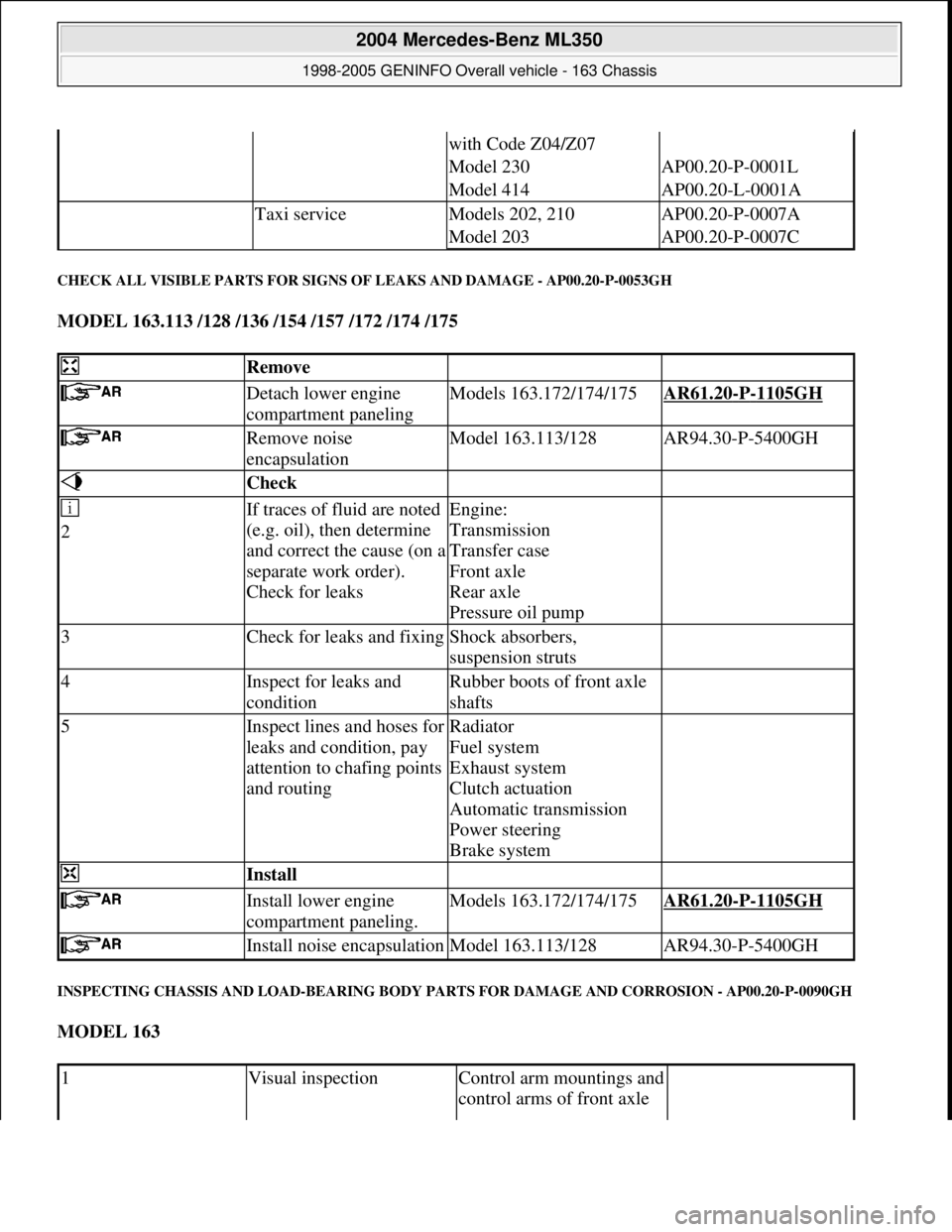
CHECK ALL VISIBLE PARTS FOR SIGNS OF LEAKS AND DAMAGE - AP00.20-P-0053GH
MODEL 163.113 /128 /136 /154 /157 /172 /174 /175
INSPECTING CHASSIS AND LOAD-BEARING BODY PARTS FOR DAMAGE AND CORROSION - AP00.20-P-0090GH
MODEL 163
with Code Z04/Z07
Model 230AP00.20-P-0001L
Model 414AP00.20-L-0001A
Taxi serviceModels 202, 210AP00.20-P-0007A
Model 203AP00.20-P-0007C
Remove
Detach lower engine
compartment panelingModels 163.172/174/175AR61.20-P-1105GH
Remove noise
encapsulationModel 163.113/128AR94.30-P-5400GH
Check
2If traces of fluid are noted
(e.g. oil), then determine
and correct the cause (on a
separate work order).
Check for leaksEngine:
Transmission
Transfer case
Front axle
Rear axle
Pressure oil pump
3Check for leaks and fixingShock absorbers,
suspension struts
4Inspect for leaks and
conditionRubber boots of front axle
shafts
5Inspect lines and hoses for
leaks and condition, pay
attention to chafing points
and routingRadiator
Fuel system
Exhaust system
Clutch actuation
Automatic transmission
Power steering
Brake system
Install
Install lower engine
compartment paneling.Models 163.172/174/175AR61.20-P-1105GH
Install noise encapsulationModel 163.113/128AR94.30-P-5400GH
1Visual inspectionControl arm mountings and
control arms of front axle
2004 Mercedes-Benz ML350
1998-2005 GENINFO Overall vehicle - 163 Chassis
me
Saturday, October 02, 2010 3:47:52 PMPage 404 © 2006 Mitchell Repair Information Company, LLC.
Page 3722 of 4133
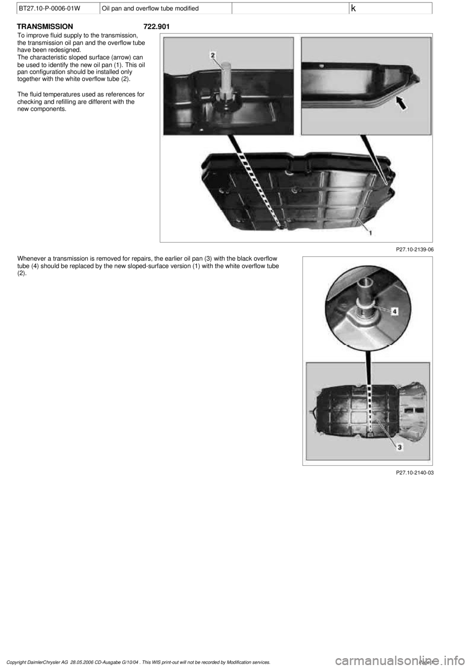
BT27.10-P-0006-01W
Oil pan and overflow tube modified
k
TRANSMISSION
722.901
P27.10-2139-06
To improve fluid supply to the transmission,
the transmission oil pan and the overflow tube
have been redesigned.
The characteristic sloped surface (arrow) can
be used to identify the new oil pan (1). This oil
pan configuration should be installed only
together with the white overflow tube (2).
The fluid temperatures used as references for
checking and refilling are different with the
new components.
Whenever a transmission is removed for repairs, the earlier oil pan (3) with the black overflow
tube (4) should be replaced by the new sloped-surface version (1) with the white overflow tube
(2).
P27.10-2140-03
Copyright DaimlerChrysler AG 28.05.2006 CD-Ausgabe G/10/04 . This WIS print-out will not be recorde
d by Modification services.
Page 1
Page 3757 of 4133

3.1
Remove viscous fan (1)
Engine 112.942 /970 and 113.942.
Right-hand thread!
AR20.40-P-5660C
3.2
Remove electric fan
Only Engine 113.965 /981.
AR20.40-P-5000GH
4.1
Pull off plate clamps of fan shroud (2)
Only for Engine 112.942, from 5/98.
5.1
Remove fan shroud (3)
Only for Engine 112.942 /970 und
113.942. Unscrew the bolts at bottom of fan
shroud for this step
Installation:
If installing a new radiator
with integral power steering pump oil cooler, a
new fan shroud is required if a radiator
without integral oil cooler was previously
installed.
6
Remove headlamp (7).
AR82.10-P-4730GH
7
Remove radiator crossmember (8)
AR62.30-P-2300GH
8
Detach coolant line (4, 6) and expansion
reservoir coolant line (5) at the radiator
Installation:
Replace the hose clamps on
the radiator fitting for the coolant hose, as
they could cause damage to the screw/thread.
Hose clamp
*BA20.20-P-1004-01A
9
Remove the rubber seal on radiator (9)
10.1
Remove oil line (return line of radiator
!
power steering pump expansion reservoir)
(18) and oil line (feed line of steering gear
!
radiator) (19)
From 5/98 only, seal off the connections.
Set of plugs
*129589009100
11
Unscrew ATF lines (10) at the radiator
Seal off the connections.
*BA20.20-P-1001-01A
*BA20.20-P-1003-01A
Set of plugs
*129589009100
12.1
Detach the connector from the fan and
remove the fan grille (11)
Only for Engine 112.942 /970 and 113.942.
13
Unscrew the condenser from the radiator
Do not disconnect the lines.
14
Remove fasteners (20) and damper rubber
(21)
The damper rubber (21) is designed to
prevent possible vibrations between the
condenser and radiator (15) during off-road
driving.
15
Remove air conditioning system fluid
reservoir (14) from the radiator
Place aside with the lines connected.
Detach the condenser from the radiator.
16
Remove radiator (15)
When installing, the spigots on the
radiator must be inserted in the rubber
grommets in the bottom crossmember.
Installation:
On Model 163.154 with
Engine 112.942 before VIN end number
043553, when installing a new radiator with
integral power steering pump oil cooler,
additional operations are required, if they
have not already been carried out:
#
v
Retrofit the bracket for the oil cooler line of
the power steering pump
SM46.30-P-0002A
k
Radiator with integral oil cooler for the power
steering pump
BT20.20-P-0001-01A
17
Detach air guides (12)
Replace the clamps on air guides (13).
18
Install in the reverse order
19
Pour in coolant
AR20.00-P-1142HA
20
Check the headlamp setting and correct if
necessary
e
Check and adjust the headlamp setting
AP82.10-P-8260GH
Danger!
Risk of accident
caused by vehicle starting
off when engine is running.
Risk of injury
caused by contusions and burns when
working in engine during starting procedure
Secure the vehicle to prevent it from moving.
Wear closed and snug-fitting work clothes.
Do not grasp hot or rotating parts.
AS00.00-Z-0005-01A
21
Check the oil level in the automatic
transmission and correct if necessary
AR27.00-P-0101A
22
Check the cooling system for leaks
AR20.00-P-1010HA
Radiator, coolant hoses
Copyright DaimlerChrysler AG 12.05.2006 CD-Ausgabe G/10/04 . This WIS print-out will not be recorde
d by Modification services.
Page 2