Page 2383 of 4133

Model 220 with engine
112, 113
Model 230 with engine
112, 113
Model 240 with engine
285AP15.10-P-1580H
Model 463 with Engine
112, 113AP15.10-P-1580GA
2.1Remove bottom engine
compartment panelingModel 240AR61.20-P-1105H
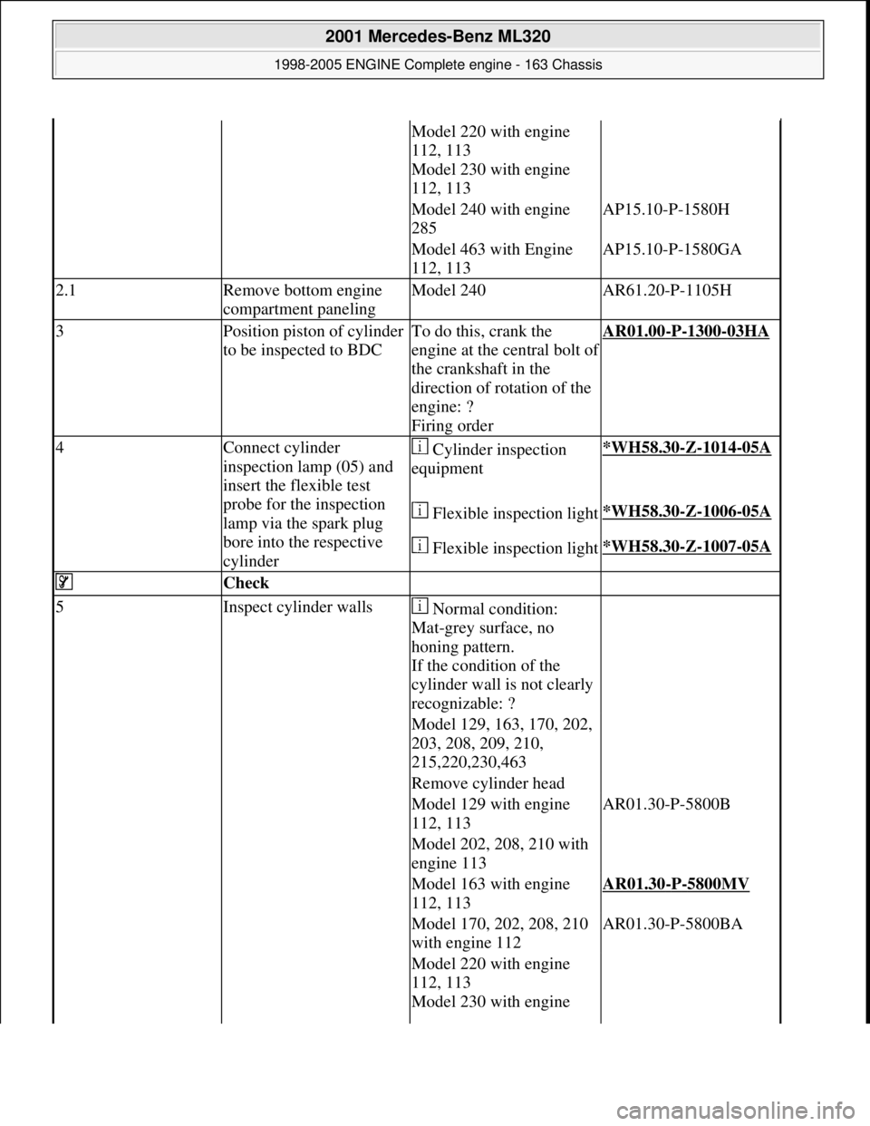
3Position piston of cylinder
to be inspected to BDCTo do this, crank the
engine at the central bolt of
the crankshaft in the
direction of rotation of the
engine: ?
Firing orderAR01.00-P-1300-03HA
4Connect cylinder
inspection lamp (05) and
insert the flexible test
probe for the inspection
lamp via the spark plug
bore into the respective
cylinder Cylinder inspection
equipment*WH58.30-Z-1014-05A
Flexible inspection light*WH58.30-Z-1006-05A
Flexible inspection light*WH58.30-Z-1007-05A
Check
5Inspect cylinder walls Normal condition:
Mat-grey surface, no
honing pattern.
If the condition of the
cylinder wall is not clearly
recognizable: ?
Model 129, 163, 170, 202,
203, 208, 209, 210,
215,220,230,463
Remove cylinder head
Model 129 with engine
112, 113AR01.30-P-5800B
Model 202, 208, 210 with
engine 113
Model 163 with engine
112, 113AR01.30-P-5800MV
Model 170, 202, 208, 210
with engine 112AR01.30-P-5800BA
Model 220 with engine
112, 113
Model 230 with engine
2001 Mercedes-Benz ML320
1998-2005 ENGINE Complete engine - 163 Chassis
me
Saturday, October 02, 2010 3:17:56 PMPage 27 © 2006 Mitchell Repair Information Company, LLC.
Page 2435 of 4133
Fig. 72: Identifying Screwdr iver Insert (000 589 03 10 00)
Fig. 73: Identifying Screwdr iver Insert (000 589 04 10 00)
Tightening pattern/bolt assignment
Left and right cylinder head M 112
1-8 Collar bolt M11 a. a Combination bolts M850( to timing case cover)
b. b Combination bolts M830(to timing case cover)
2001 Mercedes-Benz ML320
1998-2005 ENGINE Complete engine - 163 Chassis
me
Saturday, October 02, 2010 3:17:56 PMPage 79 © 2006 Mitchell Repair Information Company, LLC.
Page 2436 of 4133

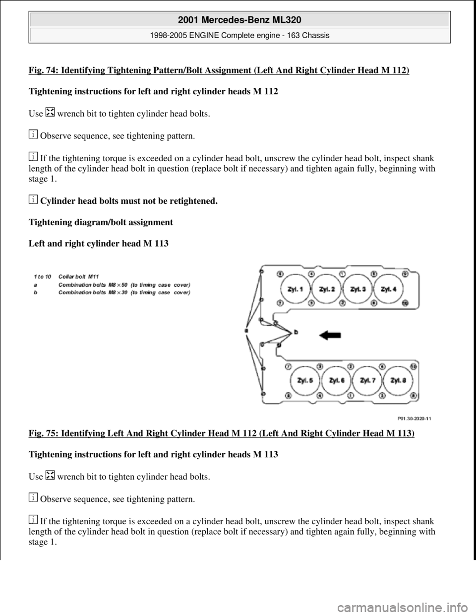
Fig. 74: Identifying Tightening Pattern/Bolt Assignment (Left And Right Cylinder Head M 112)
Tightening instructions for left and right cylinder heads M 112
Use wrench bit to tight en cylinder head bolts.
Observe sequence, see tightening pattern.
If the tightening torque is exceeded on a cylinder he ad bolt, unscrew the cylinder head bolt, inspect shank
length of the cylinder head bolt in question (replace bolt if necessary) and tighten again fully, beginning with
stage 1.
Cylinder head bolts must not be retightened.
Tightening diagram/bolt assignment
Left and right cylinder head M 113
Fig. 75: Identifying Left And Right Cylinder Head M 112 (Left And Right Cylinder Head M 113)
Tightening instructions for left and right cylinder heads M 113
Use wrench bit to tight en cylinder head bolts.
Observe sequence, see tightening pattern.
If the tightening torque is exceeded on a cylinder he ad bolt, unscrew the cylinder head bolt, inspect shank
length of the cylinder head bolt in question (replace bolt if necessary) and tighten again fully, beginning with
stage 1.
2001 Mercedes-Benz ML320
1998-2005 ENGINE Complete engine - 163 Chassis
me
Saturday, October 02, 2010 3:17:56 PMPage 80 © 2006 Mitchell Repair Information Company, LLC.
Page 2445 of 4133

28Unscrew bolts,
cylinder head -->
timing case cover
(20) *BA01.40-P-
1002-01C
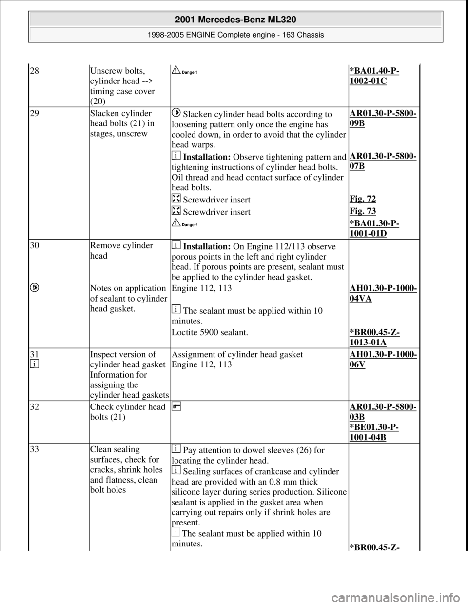
29Slacken cylinder
head bolts (21) in
stages, unscrew Slacken cylinder head bolts according to
loosening pattern only once the engine has
cooled down, in order to avoid that the cylinder
head warps.AR01.30-P-5800-
09B
Installation: Observe tightening pattern and
tightening instructions of cylinder head bolts.
Oil thread and head cont act surface of cylinder
head bolts.AR01.30-P-5800-
07B
Screwdriver insertFig. 72
Screwdriver insertFig. 73
*BA01.30-P-
1001-01D
30Remove cylinder
head Installation: On Engine 112/113 observe
porous points in the le ft and right cylinder
head. If porous points are present, sealant must
be applied to the cylinder head gasket.
Notes on application
of sealant to cylinder
head gasket.Engine 112, 113AH01.30-P-1000-
04VA
The sealant must be applied within 10
minutes.
Loctite 5900 sealant.*BR00.45-Z-
1013-01A
31
Inspect version of
cylinder head gasket
Information for
assigning the
cylinder head gasketsAssignment of cylinder head gasket
Engine 112, 113AH01.30-P-1000-
06V
32Check cylinder head
bolts (21) AR01.30-P-5800-
03B
*BE01.30
-P-
1001-04B
33Clean sealing
surfaces, check for
cracks, shrink holes
and flatness, clean
bolt holes Pay attention to dowel sleeves (26) for
locating the cylinder head.
Sealing surfaces of crankcase and cylinder
head are provided with an 0.8 mm thick
silicone layer during se ries production. Silicone
sealant is applied in the gasket area when
carrying out repairs only if shrink holes are
present.
The sealant must be applied within 10
minutes.
*BR00.45-Z-
2001 Mercedes-Benz ML320
1998-2005 ENGINE Complete engine - 163 Chassis
me
Saturday, October 02, 2010 3:17:57 PMPage 89 © 2006 Mitchell Repair Information Company, LLC.