1997 MAZDA MIATA warning
[x] Cancel search: warningPage 208 of 514

Remove rear seat cushions. Disconnect fuel pump connector. Start engine and allow to stall. After engine stalls,
attempt to restart engine to ensure no residual pressure exists. Turn ignition off and reconnect fuel pump
connector. When disconnecting fuel hoses, cover connection with shop rag to catch fuel leakage. To avoid
excessive cranking after servicing, prime fuel system before starting engine.
Priming System
Ensure fuel system is closed. Connect jumper wire between F/P and GND terminals of data link connector. See
Fig. 1
. Turn ignition on for about 10 seconds and check for fuel leaks. Turn ignition off and disconnect jumper
wire.
Fig. 1: Identifying Data Link Connector Terminals (Typical)
Courtesy of MAZDA MOTORS CORP.
COOLING SYSTEM BLEEDING
1. Slowly pour coolant into radiator at a rate of 1.1 qt. (1.0L) per minute maximum until coolant is level
with filler port. Fill coolant reservoir to "F" mark. Securely install radiator cap. Start engine.
2. Operate engine at idle until normal operating temperature is reached. If coolant level warning light
illuminates during warm-up, turn engine off and check drain plug and coolant hoses for leaks. Operate
engine at 2200-2800 RPM for 5 minutes. Stop engine and allow to cool.
3. Repeat steps 1) and 2). Check coolant level. If engine coolant is not level with filler neck, repeat entire
procedure. If engine coolant is level with filler neck, fill reservoir to "F" mark.
CAUTION: If engine overheats during procedure, system contains excessive air. Stop
engine and allow it to cool, then repeat step 1).
1997 Mazda MX-5 Miata
1997-98 ENGINES 1.8L 4-Cylinder
Microsoft
Sunday, July 05, 2009 1:55:15 PMPage 2 © 2005 Mitchell Repair Information Company, LLC.
Page 303 of 514
HEATER SYSTEM
1997 Heater System
DESCRIPTION & OPERATION
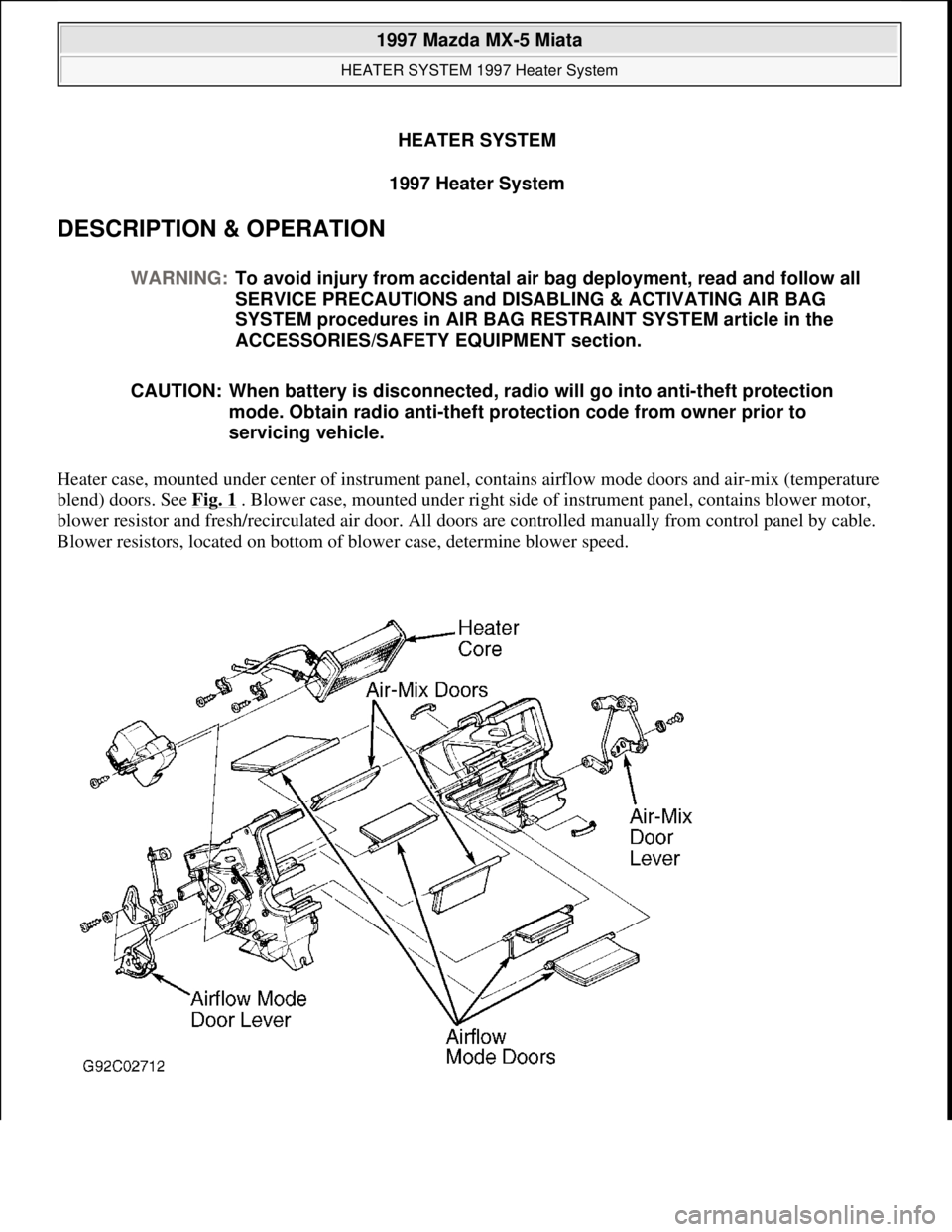
Heater case, mounted under center of instrument panel, contains airflow mode doors and air-mix (temperature
blend) doors. See Fig. 1
. Blower case, mounted under right side of instrument panel, contains blower motor,
blower resistor and fresh/recirculated air door. All doors are controlled manually from control panel by cable.
Blower resistors, located on bottom of blower case, determine blower speed. WARNING:To avoid injury from accidental air bag deployment, read and follow all
SERVICE PRECAUTIONS and DISABLING & ACTIVATING AIR BAG
SYSTEM procedures in AIR BAG RESTRAINT SYSTEM article in the
ACCESSORIES/SAFETY EQUIPMENT section.
CAUTION: When battery is disconnected, radio will go into anti-theft protection
mode. Obtain radio anti-theft protection code from owner prior to
servicing vehicle.
1997 Mazda MX-5 Miata
HEATER SYSTEM 1997 Heater System
1997 Mazda MX-5 Miata
HEATER SYSTEM 1997 Heater System
Microsoft
Sunday, July 05, 2009 1:46:56 PMPage 1 © 2005 Mitchell Repair Information Company, LLC.
Microsoft
Sunday, July 05, 2009 1:47:02 PMPage 1 © 2005 Mitchell Repair Information Company, LLC.
Page 304 of 514
Fig. 1: Exploded View Of Heater Unit
Courtesy of MAZDA MOTORS CORP.
ADJUSTMENTS
AIRFLOW MODE DOOR
Set airflow mode control lever at vent position. Disconnect control cable at airflow mode door lever. See Fig.
1 . Extend airflow mode door lever until it stops. Attach control cable to door lever. Secure cable using clip.
Ensure control lever slides freely between defrost and vent positions.
AIR-MIX (TEMPERATURE BLEND) DOOR
Set temperature control lever at maximum hot setting. Disconnect control cable at air-mix door lever. See Fig.
1 . Extend air-mix door lever until it stops. Attach control cable to door lever. Secure cable using clip. Ensure
control lever slides freely between hot and cold settings.
FRESH/RECIRCULATED AIR DOOR
Set fresh/recirculated air control lever at fresh air setting. Disconnect control cable at fresh/recirculated air door
lever. Retract recirculated/fresh air door lever until it stops. Attach control cable to door lever. Secure cable
using clip. Ensure control lever slides freely between recirculated air and fresh air settings.
TESTING
BLOWER MOTOR CIRCUIT
1. Check 30-amp HEATER fuse in passenger compartment fuse block. If fuse is okay, go to next step. If
fuse is burnt, check for short circuit in wiring harness and repair as necessary. Replace fuse.
2. Turn ignition on. Turn blower switch to 4th position (high). Using voltmeter, backprobe Blue wire
terminal of blower motor connector on bottom of blower case. If battery voltage exists, go to next step. If
battery voltage is not present, repair wiring harness between circuit breaker or fuse and blower motor.
3. Ensure ignition is on. Backprobe Blue wire terminal of blower resistor 1-pin connector. If battery voltage
exists, go to next step. If battery voltage is not present, replace blower motor.
4. Backprobe Blue/White wire terminal, Blue/Red wire terminal, Blue/Green wire terminal and Blue/Yellow
wire terminal of blower resistor 4-pin connector. If battery voltage exists, go to next step. If battery
voltage is not present at any terminal, replace blower resistor.
5. Turn blower switch to 4th position (high). Backprobe Black wire terminal of blower switch connector. If
battery voltage is not present, go to next step. If battery voltage exists, repair Black wire between blower
switch and chassis
ground. WARNING:To avoid injury from accidental air bag deployment, read and follow all
SERVICE PRECAUTIONS and DISABLING & ACTIVATING AIR BAG
SYSTEM procedures in AIR BAG RESTRAINT SYSTEM article in the
ACCESSORIES/SAFETY EQUIPMENT section.
1997 Mazda MX-5 Miata
HEATER SYSTEM 1997 Heater System
Microsoft
Sunday, July 05, 2009 1:46:56 PMPage 2 © 2005 Mitchell Repair Information Company, LLC.
Page 306 of 514
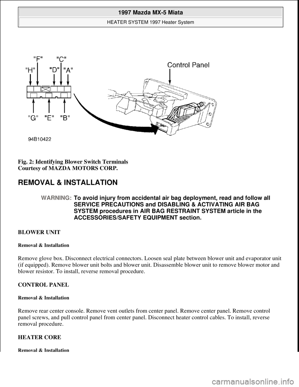
Fig. 2: Identifying Blower Switch Terminals
Courtesy of MAZDA MOTORS CORP.
REMOVAL & INSTALLATION
BLOWER UNIT
Removal & Installation
Remove glove box. Disconnect electrical connectors. Loosen seal plate between blower unit and evaporator unit
(if equipped). Remove blower unit bolts and blower unit. Disassemble blower unit to remove blower motor and
blower resistor. To install, reverse removal procedure.
CONTROL PANEL
Removal & Installation
Remove rear center console. Remove vent outlets from center panel. Remove center panel. Remove control
panel screws, and pull control panel from center panel. Disconnect heater control cables. To install, reverse
removal procedure.
HEATER CORE
Removal & Installation
WARNING:To avoid injury from accidental air bag deployment, read and follow all
SERVICE PRECAUTIONS and DISABLING & ACTIVATING AIR BAG
SYSTEM procedures in AIR BAG RESTRAINT SYSTEM article in the
ACCESSORIES/SAFETY EQUIPMENT section.
1997 Mazda MX-5 Miata
HEATER SYSTEM 1997 Heater System
Microsoft
Sunday, July 05, 2009 1:46:56 PMPage 4 © 2005 Mitchell Repair Information Company, LLC.
Page 310 of 514
A/C-HEATER SYSTEM - MANUAL
1997 Manual A/C-Heater System
A/C SYSTEM SPECIFICATIONS
A/C SYSTEM SPECIFICATIONS
DESCRIPTION
Blower assembly, mounted under right side of instrument panel, contains blower motor, blower resistor and
fresh/recirculated air door. Evaporator unit, located left of blower case, contains evaporator, evaporator
thermoswitch and expansion valve. Heater unit, located left of evaporator case, contains heater core, airflow
mode door and air-mix (temperature blend) door.
ELECTRICAL COMPONENT LOCATIONS WARNING:To avoid injury from accidental air bag deployment, read and follow all
SERVICE PRECAUTIONS and DISABLING & ACTIVATING AIR BAG
SYSTEM procedures in AIR BAG RESTRAINT SYSTEM article in the
ACCESSORIES/SAFETY EQUIPMENT section.
CAUTION: When battery is disconnected, radio will go into anti-theft protection
mode. Obtain radio anti-theft protection code from owner prior to
servicing vehicle.
ApplicationSpecifications
Compressor TypeNippondenso TV12 Rotary
Vane
Compressor Belt Deflection (1)
New5/16-23/64" (8-9 mm)
Used23/64-25/64" (9-10 mm)
Compressor Oil Capacity (2) 4.4-5.7 ozs.
Refrigerant Capacity21.2 ozs.
System Operating Pressures
High Side200-227 psi (14.0-16.0
kg/cm
2 )
Low Side22-35 psi (1.5-2.5
kg/cm
2 )
(1)Measure with 22-lb. (10 kg) pressure applied halfway between crankshaft pulley and Power Steering
(P/S) pulley or idler pulley (without P/S).
(2)Use ND-Oil 9 refrigerant oil.
1997 Mazda MX-5 Miata
A/C-HEATER SYSTEM - MANUAL 1997 Manual A/C-Heater System
1997 Mazda MX-5 Miata
A/C-HEATER SYSTEM - MANUAL 1997 Manual A/C-Heater System
Microsoft
Sunday, July 05, 2009 1:41:48 PMPage 1 © 2005 Mitchell Repair Information Company, LLC.
Microsoft
Sunday, July 05, 2009 1:41:59 PMPage 1 © 2005 Mitchell Repair Information Company, LLC.
Page 311 of 514

ELECTRICAL COMPONENT LOCATIONS
OPERATION
All air control doors are controlled manually by cable from control panel. Blower resistor determines blower
speed. With blower switch in high position, blower motor is grounded directly through blower switch. With
blower switch in all other positions, blower motor is grounded through blower resistor and blower switch.
A/C compressor clutch circuit is completed when A/C relay is energized and pressure switch is closed. A/C
relay is energized when Powertrain Control Module (PCM) grounds the solenoid circuit of the relay. The PCM
energizes A/C relay if evaporator thermoswitch is closed and A/C and blower switches are on. The PCM also
controls A/C relay operation according to engine load.
ADJUSTMENTS
TESTING
A/C SYSTEM PERFORMANCE
1. Connect manifold gauge set. Operate engine at 1500 RPM. Operate A/C at maximum cooling, recirculate,
fan on high, vent mode. Close all doors and windows. Place thermometer at center vent outlet.
2. Allow A/C to stabilize. Ensure high pressure is 200-227 psi (14.0-16.0 kg/cm
2 ). Read temperature at
center vent outlet. Ensure temperature is within 39-43°F (3-6°C)
A/C COMPRESSOR CLUTCH CIRCUIT
ComponentLocation
A/C RelayRight Front Corner Of Engine Compartment
Condenser FanRight Front Corner Of Engine Compartment
Blower ResistorBottom Of Blower Case
Evaporator ThermoswitchOn Evaporator Upper Case
Pressure SwitchIn High-Pressure Line, Between Receiver-Drier &
Evaporator
NOTE: For door control cable adjustments, see ADJUSTMENTS in HEATER SYSTEM
article.
WARNING:To avoid injury from accidental air bag deployment, read and follow all
SERVICE PRECAUTIONS and DISABLING & ACTIVATING AIR BAG
SYSTEM procedures in AIR BAG RESTRAINT SYSTEM article in the
ACCESSORIES/SAFETY EQUIPMENT section.
NOTE: For test procedures not covered in this article, see TESTING in HEATER
SYSTEM article.
1997 Mazda MX-5 Miata
A/C-HEATER SYSTEM - MANUAL 1997 Manual A/C-Heater System
Microsoft
Sunday, July 05, 2009 1:41:48 PMPage 2 © 2005 Mitchell Repair Information Company, LLC.
Page 316 of 514
COMPRESSOR
Removal & Installation
1. Before disconnecting negative battery cable, obtain radio anti-theft code from vehicle owner. Disconnect
negative battery cable.
2. Raise and support front of vehicle with safety stands. Discharge A/C system using approved refrigerant
recovery/recycling equipment. Remove splash shield and air guide.
3. Disconnect compressor clutch connector. Disconnect refrigerant lines from compressor, and plug open
fittings. Remove compressor drive belt. Remove compressor bolts and compressor. To install, reverse
removal procedure. Adjust drive belt deflection. Apply clean compressor oil to "O" ring before
connecting fittings. DO NOT apply compressor oil to fitting nuts. Evacuate and charge A/C system.
Check for leaks.
CONDENSER & RECEIVER-DRIER
Removal
Raise and support front of vehicle with safety stands. Discharge A/C system using approved refrigerant
recovery/recycling equipment. Remove splash shield and air guide. Remove condenser. Remove receiver-drier.
Plug open fittings.
Installation
To install, reverse removal procedure. Apply clean compressor oil to "O" rings before connecting fittings. DO
NOT apply compressor oil to fitting nuts. If installing new condenser, add 1.0 ounce of compressor oil to A/C
compressor. If installing new receiver-drier, add .3 ounce of compressor oil to A/C compressor. Evacuate and
charge A/C system. Check for leaks.
EVAPORATOR UNIT
Removal
1. Discharge A/C system using approved refrigerant recovery/recycling equipment. Disconnect refrigerant
pipes from evaporator tubes at engine compartment firewall and plug open fittings. Remove passenger-
side instrument panel undercover. Remove glove box.
2. Disconnect electrical connectors. Loosen seal plates between evaporator unit, heater unit and blower unit.
Remove evaporator unit. Disassemble evaporator unit to remove evaporator core and thermo-switch. See WARNING:To avoid injury from accidental air bag deployment, read and follow all
SERVICE PRECAUTIONS and DISABLING & ACTIVATING AIR BAG
SYSTEM procedures in AIR BAG RESTRAINT SYSTEM article in the
ACCESSORIES/SAFETY EQUIPMENT section.
NOTE: For removal and installation procedures not covered in this article, see HEATER
SYSTEM article.
1997 Mazda MX-5 Miata
A/C-HEATER SYSTEM - MANUAL 1997 Manual A/C-Heater System
Microsoft
Sunday, July 05, 2009 1:41:48 PMPage 7 © 2005 Mitchell Repair Information Company, LLC.
Page 324 of 514
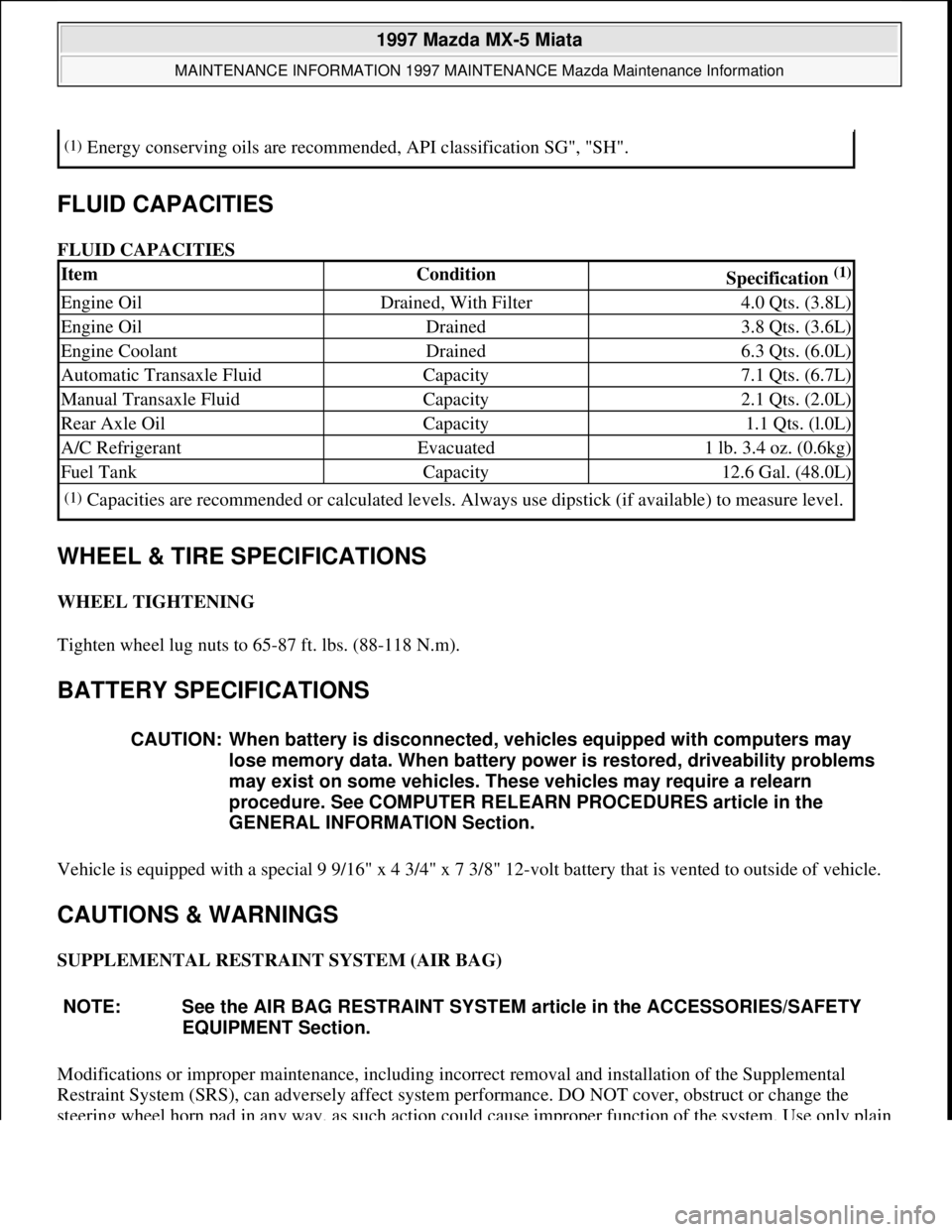
FLUID CAPACITIES
FLUID CAPACITIES
WHEEL & TIRE SPECIFICATIONS
WHEEL TIGHTENING
Tighten wheel lug nuts to 65-87 ft. lbs. (88-118 N.m).
BATTERY SPECIFICATIONS
Vehicle is equipped with a special 9 9/16" x 4 3/4" x 7 3/8" 12-volt battery that is vented to outside of vehicle.
CAUTIONS & WARNINGS
SUPPLEMENTAL RESTRAINT SYSTEM (AIR BAG)
Modifications or improper maintenance, including incorrect removal and installation of the Supplemental
Restraint System (SRS), can adversely affect system performance. DO NOT cover, obstruct or change the
steerin
g wheel horn pad in any way, as such action could cause improper function of the system. Use only plain
(1)Energy conserving oils are recommended, API classification SG", "SH".
ItemConditionSpecification (1)
Engine OilDrained, With Filter4.0 Qts. (3.8L)
Engine OilDrained3.8 Qts. (3.6L)
Engine CoolantDrained6.3 Qts. (6.0L)
Automatic Transaxle FluidCapacity7.1 Qts. (6.7L)
Manual Transaxle FluidCapacity2.1 Qts. (2.0L)
Rear Axle OilCapacity1.1 Qts. (l.0L)
A/C RefrigerantEvacuated1 lb. 3.4 oz. (0.6kg)
Fuel TankCapacity12.6 Gal. (48.0L)
(1)Capacities are recommended or calculated levels. Always use dipstick (if available) to measure level.
CAUTION: When battery is disconnected, vehicles equipped with computers may
lose memory data. When battery power is restored, driveability problems
may exist on some vehicles. These vehicles may require a relearn
procedure. See COMPUTER RELEARN PROCEDURES article in the
GENERAL INFORMATION Section.
NOTE: See the AIR BAG RESTRAINT SYSTEM article in the ACCESSORIES/SAFETY
EQUIPMENT Section.
1997 Mazda MX-5 Miata
MAINTENANCE INFORMATION 1997 MAINTENANCE Mazda Maintenance Information
Microsoft
Sunday, July 05, 2009 1:41:19 PMPage 4 © 2005 Mitchell Repair Information Company, LLC.