1997 MAZDA MIATA Shift
[x] Cancel search: ShiftPage 173 of 514
GENERAL INFORMATION
Computer Relearn Procedures
COMPUTER RELEARN PROCEDURES
Vehicles equipped with engine or transmission computers may require a relearn procedure after vehicle battery
is disconnected. Many vehicle computers memorize and store vehicle operation patterns for optimum
driveability and performance. When vehicle battery is disconnected, this memory is lost. The computer will use
default data until new data from each key start is stored. As computer memorizes vehicle operation for each
new key start, driveability is restored. Vehicle computers may memorize vehicles operation patterns for 40 of
more key starts.
Customers often complain of driveability problems during relearn stage because vehicle acts differently then
before being serviced. Depending on type and make of vehicle and how it is equipped, the following complaints
(driveability problems) may exist:
Harsh Or Poor Shift Quality
Rough Or Unstable Idle
Hesitation Or Stumble
Rich Or Lean Running
Poor Fuel Mileage
These symptoms and complaints should disappear after a number of drive cycles have been memorized. To
reduce the possibility of complaints, after any service which requires battery power to be disconnected, vehicle
should be road tested.
GENERIC COMPUTER RELEARN PROCEDURES
Some manufacturers identify a specific relearn procedure which will help establish suitable driveability during
relearn stage. These procedures are especially important if vehicle is equipped with and electronically
controlled automatic transmission or transaxle. Always complete procedure before returning vehicle to
customer. The following general procedures are to be used if driveability problems are encountered after power
loss or battery has been disconnected. These procedures may provide an aid in eliminating these problems.
Automatic Transmission
Set parking brake, start engine in "P" or "N" position. Warm-up vehicle to normal operating temperature
or until cooling fan cycles.
Allow vehicle to idle for one minute in "N" position. Select "D" and allow engine to idle for one minute.
Accelerate at normal throttle position (20-50%) until vehicle shifts into top gear.
Cruise at light to medium throttle.
Decelerate to a stop, allowing vehicle to downshift, and use brakes normally.
Process may be repeated as necessary.
1997 Mazda MX-5 Miata
GENERAL INFORMATION Computer Relearn Procedures
1997 Mazda MX-5 Miata
GENERAL INFORMATION Computer Relearn Procedures
Microsoft
Sunday, July 05, 2009 1:47:32 PMPage 1 © 2005 Mitchell Repair Information Company, LLC.
Microsoft
Sunday, July 05, 2009 1:47:35 PMPage 1 © 2005 Mitchell Repair Information Company, LLC.
Page 199 of 514

MOTORS
MOTORS
SENDING UNITS & SENSORS
SENDING UNITS & SENSORS
Key Interlock UnitBehind left side of dash. See Fig. 2 .
SAS UnitBehind center of dash. See Fig. 2 .
Transmission Control Module (TCM)Under left side of dash, near fuse block. See Fig. 2 .
ComponentComponent Location
Blower MotorUnder right side of dash. See Fig. 2 .
Condenser Fan MotorIn front of engine compartment.
Cooling Fan MotorIn front of engine compartment.
Cruise Control ActuatorOn left side of engine compartment.
Fuel PumpIn fuel tank.
Power Antenna MotorIn right front of trunk.
Retractable Headlamp ActuatorsBehind respective headlamp.
Shift Lock ActuatorUnder center console, on base of gear selector.
Windshield Washer MotorOn bottom of washer fluid reservoir.
Windshield Wiper MotorOn right side of firewall.
ComponentComponent Location
ABS Wheel Speed Sensor (Left Front)On back of left front wheel spindle assembly. See Fig. 1 .
ABS Wheel Speed Sensor (Left Rear)On back of left rear wheel hub assembly. See Fig. 3 .
ABS Wheel Speed Sensor (Right Front)On back of right front wheel spindle assembly. See Fig. 1 .
ABS Wheel Speed Sensor (Right Rear)On back of right rear wheel hub assembly. See Fig. 3 .
Brake Fluid Level SensorIn brake fluid reservoir. See Fig. 1 .
Camshaft Position SensorIn center rear of engine compartment. See Fig. 1 .
Crankshaft Position SensorOn front of engine.
EGR Boost SensorOn right side of engine compartment.
EGR Valve Position SensorOn right side center, rear of engine compartment.
EGR Valve Position SensorOn right side center, rear of engine compartment. See Fig. 1 .
Engine Coolant Temperature SensorOn rear of engine. See Fig. 1 .
Fuel Gauge Sender UnitIn fuel tank.
Heated Oxygen Sensor (Front)In rear of engine compartment. See Fig. 1 .
Heated Oxygen Sensor (Rear)On underside of vehicle, on exhaust pipe.
Input/Turbine Speed SensorOn left side of transmission.
Mass Air Flow SensorOn top of air filter housing. See Fig. 1 .
Throttle Position (TP) SensorOn side of throttle body. See Fig. 1 .
Transmission Fluid Temperature SensorOn left side of transmission.
1997 Mazda MX-5 Miata
1997 MAZDA MX-5 Miata
Microsoft
Sunday, July 05, 2009 1:54:00 PMPage 2 © 2005 Mitchell Repair Information Company, LLC.
Page 212 of 514
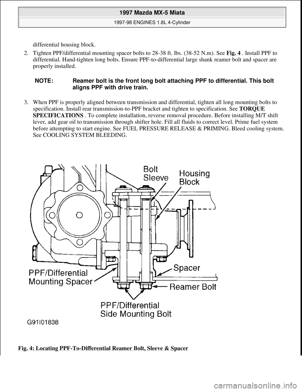
differential housing block.
2. Tighten PPF/differential mounting spacer bolts to 28-38 ft. lbs. (38-52 N.m). See Fig. 4
. Install PPF to
differential. Hand-tighten long bolts. Ensure PPF-to-differential large shank reamer bolt and spacer are
properly installed.
3. When PPF is properly aligned between transmission and differential, tighten all long mounting bolts to
specification. Install rear transmission-to-PPF bracket and tighten to specification. See TORQUE
SPECIFICATIONS . To complete installation, reverse removal procedure. Before installing M/T shift
lever, add gear oil to transmission through shifter hole. Fill all fluids to correct level. Prime fuel system
before attempting to start engine. See FUEL PRESSURE RELEASE & PRIMING. Bleed cooling system.
See COOLING SYSTEM BLEEDING.
Fig. 4: Locating PPF
-To-Differential Reamer Bolt, Sleeve & Spacer
NOTE: Reamer bolt is the front long bolt attaching PPF to differential. This bolt
aligns PPF with drive train.
1997 Mazda MX-5 Miata
1997-98 ENGINES 1.8L 4-Cylinder
Microsoft
Sunday, July 05, 2009 1:55:15 PMPage 6 © 2005 Mitchell Repair Information Company, LLC.
Page 214 of 514

Fig. 5: Removing Engine Components (Protege)
Courtesy of MAZDA MOTORS CORP.
2. Lower vehicle. Remove air cleaner assembly. Remove battery/carrier assembly. Remove throttle cable
and air intake duct across radiator (if equipped).
3. Remove all drive belts. DO NOT disconnect power steering hoses or A/C compressor hoses. Unbolt
power steering pump and A/C compressor from engine, and wire aside.
4. Note locations and disconnect all necessary electrical connectors, ground wires, vacuum hoses, fuel
hoses, coolant hoses and control cables for engine removal.
5. Plug all fuel hoses to avoid leakage. Attach engine support bar or engine hoist to secure engine. Raise
vehicle. Disconnect exhaust manifold down pipe and exhaust brackets from engine. On A/T models,
remove shift control cable.
6. On M/T models, remove shift control linkage and extension bar. Remove clutch release cylinder and fluid
line bracket from transaxle housing, leaving fluid line connected to cylinder. Secure cylinder away from
transaxle.
7. On all models, remove transmission wiring harness connectors and speedometer cable. Remove axle shaft
nuts from hubs. Disconnect stabilizer bar from lower control arms. Separate lower ball joints and steering
tie-rod ends from steering knuckles.
8. Pry axle shafts out of transaxle. Remove and discard circlip from axle shafts. For further information on
axle shafts, see appropriate article in DRIVE AXLES.
9. Remove transaxle mount nuts from crossmember and loosen crossmember bolts. See Fig. 6
. Lower
vehicle and attach engine hoist for engine removal. Remove engine front mount and transaxle top mount
from inner fender panels. Remove transaxle crossmember. Remove engine and transaxle assembly from
top of vehicle.
10. To install, reverse removal procedure. Tighten bolts and nuts to specifications. See TORQUE
SPECIFICATIONS . Fill all fluids to correct level. Prime fuel system before attempting to start engine.
See FUEL PRESSURE RELEASE & PRIMING
. Bleed cooling system. See COOLING SYSTEM
BLEEDING.
1997 Mazda MX-5 Miata
1997-98 ENGINES 1.8L 4-Cylinder
Microsoft
Sunday, July 05, 2009 1:55:15 PMPage 8 © 2005 Mitchell Repair Information Company, LLC.
Page 331 of 514
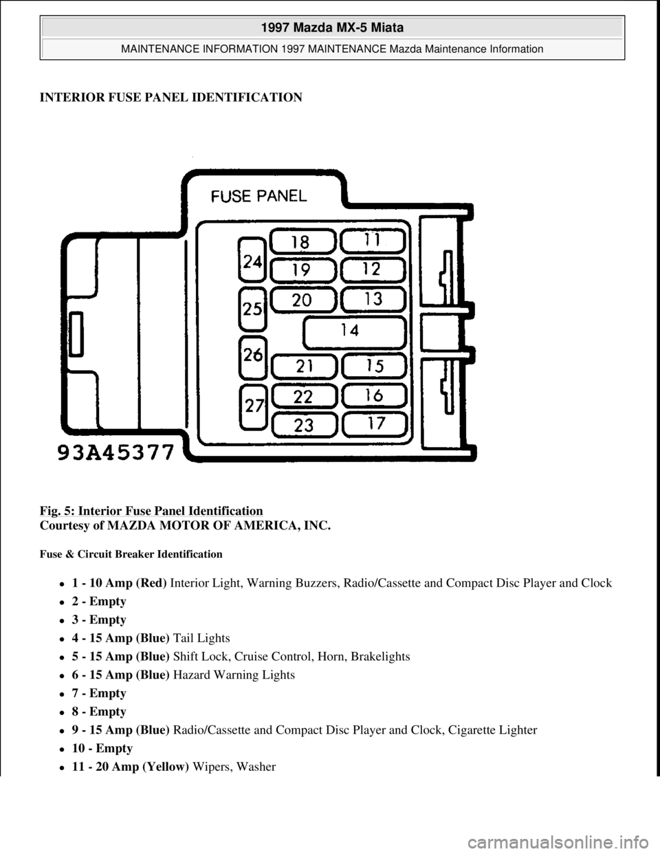
INTERIOR FUSE PANEL IDENTIFICATION
Fig. 5: Interior Fuse Panel Identification
Courtesy of MAZDA MOTOR OF AMERICA, INC.
Fuse & Circuit Breaker Identification
1 - 10 Amp (Red) Interior Light, Warning Buzzers, Radio/Cassette and Compact Disc Player and Clock
2 - Empty
3 - Empty
4 - 15 Amp (Blue) Tail Lights
5 - 15 Amp (Blue) Shift Lock, Cruise Control, Horn, Brakelights
6 - 15 Amp (Blue) Hazard Warning Lights
7 - Empty
8 - Empty
9 - 15 Amp (Blue) Radio/Cassette and Compact Disc Player and Clock, Cigarette Lighter
10 - Empty
11 - 20 Amp (Yellow) Wipers, Washer
1997 Mazda MX-5 Miata
MAINTENANCE INFORMATION 1997 MAINTENANCE Mazda Maintenance Information
Microsoft
Sunday, July 05, 2009 1:41:19 PMPage 11 © 2005 Mitchell Repair Information Company, LLC.
Page 334 of 514
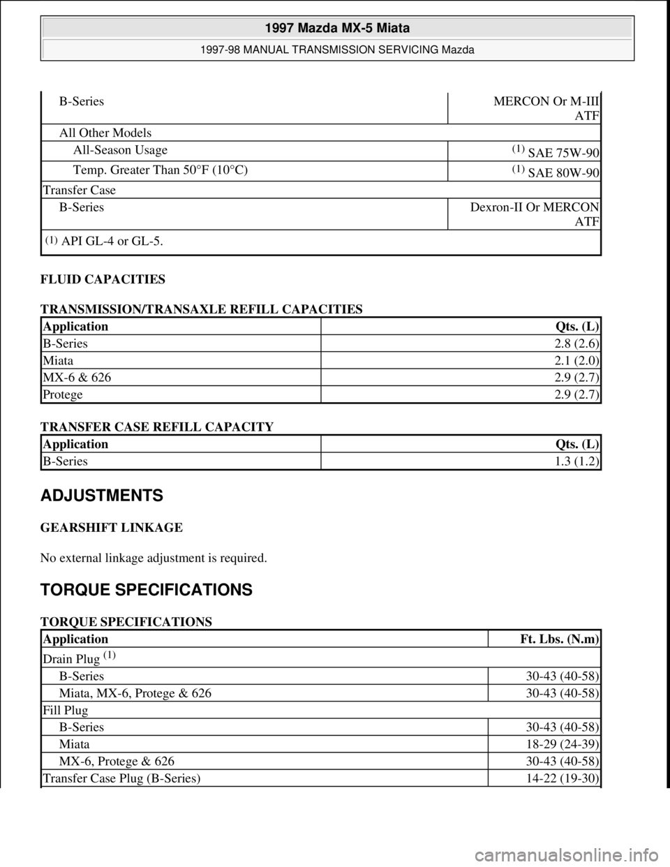
FLUID CAPACITIES
TRANSMISSION/TRANSAXLE REFILL CAPACITIES
TRANSFER CASE REFILL CAPACITY
ADJUSTMENTS
GEARSHIFT LINKAGE
No external linkage adjustment is required.
TORQUE SPECIFICATIONS
TORQUE SPECIFICATIONS
B-SeriesMERCON Or M-III
ATF
All Other Models
All-Season Usage(1) SAE 75W-90
Temp. Greater Than 50°F (10°C)(1) SAE 80W-90
Transfer Case
B-SeriesDexron-II Or MERCON
ATF
(1)API GL-4 or GL-5.
ApplicationQts. (L)
B-Series2.8 (2.6)
Miata2.1 (2.0)
MX-6 & 6262.9 (2.7)
Protege2.9 (2.7)
ApplicationQts. (L)
B-Series1.3 (1.2)
ApplicationFt. Lbs. (N.m)
Drain Plug (1)
B-Series30-43 (40-58)
Miata, MX-6, Protege & 62630-43 (40-58)
Fill Plug
B-Series30-43 (40-58)
Miata18-29 (24-39)
MX-6, Protege & 62630-43 (40-58)
Transfer Case Plug (B-Series)14-22 (19-30)
1997 Mazda MX-5 Miata
1997-98 MANUAL TRANSMISSION SERVICING Mazda
Microsoft
Sunday, July 05, 2009 1:37:16 PMPage 2 © 2005 Mitchell Repair Information Company, LLC.
Page 406 of 514
STEERING WHEEL .
COMBINATION SWITCH .
Disconnect ignition switch connectors. Remove key interlock cable from ignition switch/steering lock
assembly (if equipped).
2. Using a hammer and chisel, make a groove in ignition switch/steering lock assembly shear screws.
Remove 2 shear screws with screwdriver. Remove ignition switch/steering lock assembly. To install,
reverse removal procedure. Tighten NEW shear screws until heads break off.
STEERING COLUMN
Removal & Installation
1. Remove driver air bag module, steering wheel and combination switch. See the following:
DRIVER AIR BAG MODULE .
STEERING WHEEL .
COMBINATION SWITCH .
See Fig. 5
-11 . Remove ignition switch/steering lock assembly. See IGNITION SWITCH/STEERING
LOCK ASSEMBLY under REMOVAL & INSTALLATION.
2. Remove lower panel. Remove air duct (if equipped). Remove "U" joint dust cover (if equipped). Remove
steering shaft assembly-to-intermediate shaft "U" joint bolt. Mark steering shaft assembly-to-intermediate
shaft for installation reference. On MPV, disconnect shift lever mechanism.
3. On all models, remove steering column lower mounting bolts. Separate steering shaft from intermediate
shaft. Remove steering column upper bracket bolts. Remove steering column.
4. To install, reverse removal procedure. Tighten bolts and nuts to specification. See TORQUE
SPECIFICATIONS table. CAUTION: Excessive pressure or impact to steering shaft assembly during service
may cause column to collapse.
1997 Mazda MX-5 Miata
STEERING COLUMN 1995-97 STEERING Mazda Motors Corp. - Steering Columns
Microsoft
Sunday, July 05, 2009 1:40:02 PMPage 8 © 2005 Mitchell Repair Information Company, LLC.
Page 498 of 514
Fig. 24: Premium Sound Radio Circuit
SHIFT INTERLOCKS
1997 Mazda MX-5 Miata
1997 System Wiring Diagrams Mazda - Miata
Microsoft
Sunday, July 05, 2009 1:31:52 PMPage 49 © 2005 Mitchell Repair Information Company, LLC.