Page 4 of 1600
4B-8 REAR AXLE
AXLE SHAFT
DISASSEMBLY
1. Refer to Section 3E "WHEEL and TIRE" for road wheel Disassembly procedure.
2. Refer to Section 5 "BRAKE" for rear brake removal procedure.
Disassembly Steps
1. Wheel and tire
2. Brake drum
3. Bolt and nut
4. Axle shaft assembly
5. Shim
6. Bearing nut and lock washer
7. Bearing holder
8. Bearing
9. Oil seal
10. Bearing outer race
11. Wheel pin
12. Oil seal
Page 5 of 1600

REAR AXLE 4B-9
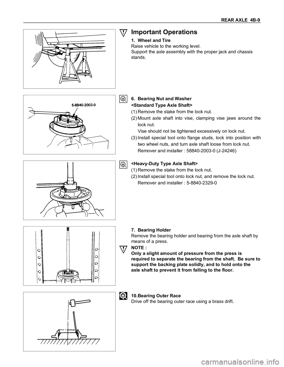
Important Operations
1. Wheel and Tire
Raise vehicle to the working level.
Support the axle assembly with the proper jack and chassis
stands.
6. Bearing Nut and Washer
(1) Remove the stake from the lock nut.
(2) Mount axle shaft into vise, clamping vise jaws around the
lock nut.
Vise should not be tightened excessively on lock nut.
(3) Install special tool onto flange studs, lock into position with
two wheel nuts, and turn axle shaft loose from lock nut.
Remover and installer : 58840-2003-0 (J-24246)
(1) Remove the stake from the lock nut.
(2) Install special tool onto lock nut, and remove the lock nut.
Remover and installer : 5-8840-2329-0
7. Bearing Holder
Remove the bearing holder and bearing from the axle shaft by
means of a press.
NOTE :
Only a slight amount of pressure from the press is
required to separate the bearing from the shaft. Be sure to
support the backing plate solidly, and to hold onto the
axle shaft to prevent it from falling to the floor.
10.Bearing Outer Race
Drive off the bearing outer race using a brass drift.
Page 6 of 1600
4B-10 REAR AXLE
11.Wheel Pin
Remove the wheel pins from the axle shaft flange.
Remover : 5-8840-0079-0
(J-6627-A)
Page 8 of 1600
4B-12 REAR AXLE
REASSEMBLY
1. Refer to Section 3E "WHEEL and TIRE" for road wheel reassembly procedure.
2. Refer to Section 5 "BRAKE" for rear brake installation procedure.
Reassembly Steps
1. Wheel pin
2. Bearing outer race
3. Oil seal
4. Bearing holder
5. Bearing
6. Axle shaft assembly
7. Bearing nut and lock washer
8. Oil seal
9. Shim
10. Bolt and nut
11. Brake drum
12. Wheel and tire
Page 11 of 1600
REAR AXLE 4B-15
Install the axle shaft assembly on the opposite side and push it
in until it fits against the differential thrust block. Then,
measure the clearance (t) between the bearing holder and the
axle case flange and determine the thickness of the shim to be
installed by the following formula :
Measured clearance (t) + 0.3 mm (0.012 in) = thickness of
shim to be installed.
mm(in)
thickness of shims available
1.0, 0.5, 0.13, 0.076, 0.05
(0.036, 0.026, 0.005, 0.003, 0.002)
10.Bolt and Nut
Torque N
m (kgfm/lbft)
74
5 (7.5 0.5 / 54 3.6)
Connect the brake lines to wheel cylinder.
Connect the parking brake rear cable.
Brake air bleeding, refer to servicing to Section 5 brake.
Note :
To install the axle shaft assembly, follow the reassembly
procedure outline under the "BRAKE".
12.Wheel and Tire
Tighten the wheel nut in numerical order.
Torque N
m (kgfm/lbft)
117.7
9.8 (12 1/86.8 7.2)
Page 48 of 1600
4B-52 REAR AXLE
TROUBLESHOOTING
Refer to this Section to quickly diagnose and repair rear axle problems.
Each troubleshooting chart has three headings arranged from left to right.
(1) Checkpoint (2) Trouble Cause (3) Countermeasure
This Section is divided into five sub-sections:
1. Abnormal Rear Axle Noise
1) Noise when the engine is driving the vehicle
2) Noise when the vehicle is coasting
3) Intermittent noise
4) Noise when the vehicle is turning
5) Constant noise
2. Vibration
3. Oil Leakage
1) Differential carrier leakage
2) Axle case leakage
3) Axle case to inside hub leakage
4) Axle case to inside brake drum leakage
4. Power Not Being Transmitted to the Wheels (Propeller Shaft Operation is Normal)
Page 58 of 1600
4B-62 REAR AXLE
4. POWER NOT BEING TRANSMITTED TO THE WHEELS
(PROPELLER SHAFT OPERATION IS NORMAL)
Checkpoint Trouble Cause Countermeasure
Replace the rear axle shaftBroken rear axle shaft NG
Replace the drive pinion and
the ring gear as a setDrive pinion and ring gearBroken drive pinion and/or ring
gear
Replace the differential gears
and/or the spiderDifferential cage gearsBroken differential cage gears
and/or spider NG NG
OK OK
Rear axle shaft
Page 59 of 1600
REAR AXLE 4B-63
SPECIAL SERVICE TOOL
ITEM NO. ILLUSTRATION PART NO. PART NAME
RAL-1
5-8840-2003-0
(J-24246)Axle shaft bearing nut
remover & installer
RAL-25-8840-2329-0Axle shaft bearing nut
remover & installer
(Heavy-Duty type)
RAL-3
5-8840-0079-0
(J-6627-A) Wheel pin remover
RAL-4
5-8522-1268-0
(J-24259)Axle shaft bearing outer
race installer (for 194mm)
5-8840-2201-0 194mm (H/D), 220mm
OTL-1
5-8840-0007-0
(J-8092) Driver handle
RAL-35
9-8522-1269-0
(J-24255)Bearing holder oil seal
installer (for 194mm)
RAL-115-8840-2202-0Bearing holder oil seal
installer (for 194mm H/D,
220mm)
RAL-6
9-8522-1271-0
(J-8609-01) Axle shaft bearing installer