Page 31 of 1600
REAR AXLE 4B-35
Reassembly Steps
1. Differential cage
2. Thrust washer
3. Bellve disc
4. Bellve disc
5. Friction plate
6. Friction disc
7. Friction plate
8. Friction disc
9. Pressure ring
10. Side gear
11. Pinion gear and pinion spider
12. Thrust block13. Side gear
14. Pressure ring
15. Friction disc
16. Friction plate
17. Friction disc
18. Friction plate
19. Bellve disc
20. Bellve disc
21. Thrust washer
22. Differential cage cover
23. Bolt
Page 32 of 1600

4B-36 REAR AXLE
Adjustment of Clearance between
Friction Disc and Plate
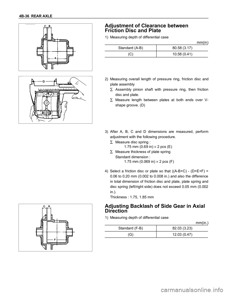
1) Measuring depth of differential case
mm(in)
Standard (A-B) 80.58 (3.17)
(C) 10.58 (0.41)
2) Measuring overall length of pressure ring, friction disc and
plate assembly
Assembly pinion shaft with pressure ring, then friction
disc and plate.
Measure length between plates at both ends over V-
shape groove. (D)
3) After A, B, C and D dimensions are measured, perform
adjustment with the following procedure.
Measure disc spring :
1.75 mm (0.69 in)
2 pcs (E)
Measure thickness of plate spring
Standard dimension :
1.75 mm (0.069 in)
2 pcs (F)
4) Select a friction disc or plate so that ((A-B+C) - (D+E+F) =
0.06 to 0.20 mm (0.002 to 0.008 in.) and also the difference
in total dimension of friction disc and plate, plate spring and
disc spring (left/right side) does not exceed 0.05 mm (0.002
in.).
Thickness : 1.75, 1.85 mm
Adjusting Backlash of Side Gear in Axial
Direction
1) Measuring depth of differential case
mm(in.)
Standard (F-B) 82.03 (3.23)
(G) 12.03 (0.47)
Page 33 of 1600

REAR AXLE 4B-37
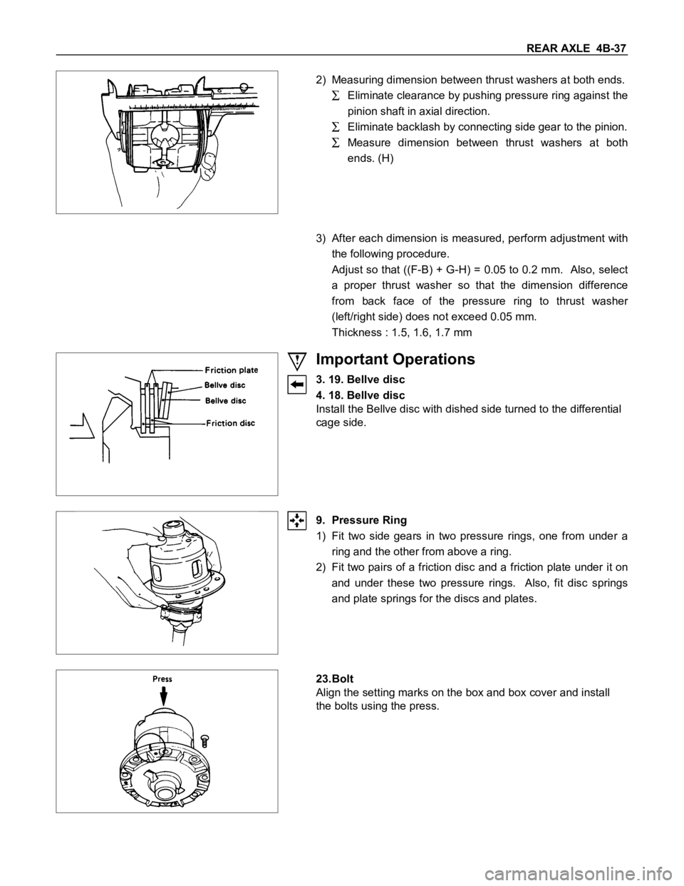
2) Measuring dimension between thrust washers at both ends.
Eliminate clearance by pushing pressure ring against the
pinion shaft in axial direction.
Eliminate backlash by connecting side gear to the pinion.
Measure dimension between thrust washers at both
ends. (H)
3) After each dimension is measured, perform adjustment with
the following procedure.
Adjust so that ((F-B) + G-H) = 0.05 to 0.2 mm. Also, select
a proper thrust washer so that the dimension difference
from back face of the pressure ring to thrust washer
(left/right side) does not exceed 0.05 mm.
Thickness : 1.5, 1.6, 1.7 mm
Important Operations
3. 19. Bellve disc
4. 18. Bellve disc
Install the Bellve disc with dished side turned to the differential
cage side.
9. Pressure Ring
1) Fit two side gears in two pressure rings, one from under a
ring and the other from above a ring.
2) Fit two pairs of a friction disc and a friction plate under it on
and under these two pressure rings. Also, fit disc springs
and plate springs for the discs and plates.
23.Bolt
Align the setting marks on the box and box cover and install
the bolts using the press.
Page 35 of 1600
REAR AXLE 4B-39
DIFFERENTIAL ASSEMBLY (STD)
Reassembly Steps
1. Differential cage
2. Thrust washer
3. Side gear
4. Pinion gear
5. Thrust block
6. Cross pin
7. Lock pin
8. Ring gear
Page 36 of 1600
4B-40 REAR AXLE
Important Operations
4. Pinion Gear
Install the pinion gear by engaging it with the side gears while
turning both pinion gears simultaneously in the same direction.
6. Cross Pin
(1) Be sure to install the cross pin so that it is in alignment with
the lock pin hole in the differential cage.
(2) Backlash between the side gear and the pinion gear.
Backlash mm(in)
194 mm 0.03 - 0.08 (0.001 - 0.003)
220 mm 0.13 - 0.18 (0.005 - 0.007)
If the backlash is beyond the limits, adjust with a thrust washer
of selected thickness.
Thicknesses of thrust washers available.
mm(in)
194 mm1.00
(0.039)1.05
(0.041)1.10
(0.043)
220 mm0.80
(0.031)0.90
(0.035)1.00
(0.039)1.10
(0.043)1.20
(0.047)1.30
(0.051)
7. Lock Pin
After lock pin installation, stake the cage to prevent the lock pin
from falling out.
Page 38 of 1600
4B-42 REAR AXLE
MAJOR COMPONENTS
Reassembly Steps
1. Outer bearing outer race
2. Inner bearing outer race
3. Pinion depth adjusting ; shim
4. Inner bearing
5. Collapsible spacer
6. Friction disc
7. Outer bearing
8. Oil seal
9. Pinion flange assembly
10. Flange nut and washer
11. Backlash and pre-load adjusting shim
12. Side bearings
13. Side bearing outer race
14. Differential cage assembly and ring gear
15. Bearing cap
16. Bolt
17. Differential assembly
Page 44 of 1600

4B-48 REAR AXLE
(3) Pinion bearing preload.
(a) Measure the bearing preload by using a torque wrench.
Note the scale reading required to rotate the flange.
(b) Continue tightening until the specified starting torque is
obtained.
Pinion Bearing Preload Starting Torque N
m (kgfm/lbft)
194 mm 64 - 113 (6.5 - 11.5/47 - 72)
220 mm 69 - 127 (7 - 13/51 - 94)
11.Backlash and Pre-load Adjusting Shim
(1) Attach the side bearing to the differential assembly without
shims. Support the opposite side using a pilot to prevent
bearing damage.
1Installer : 9-8522-1164-0 (194 mm)
(J-24244)
: 5-8840-2162-0 (220 mm)
(J-37257)
2Drive handle : 5-8840-0007-0
(J-8092)
3Pilot : 9-8521-1743-0
(J-8107-2)
(2) Position the differential cage assembly with the bearing
outer races to the side bearing bores of the carrier.
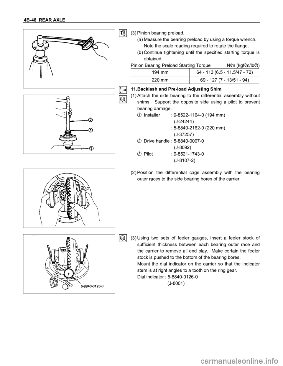
(3) Using two sets of feeler gauges, insert a feeler stock of
sufficient thickness between each bearing outer race and
the carrier to remove all end play. Make certain the feeler
stock is pushed to the bottom of the bearing bores.
Mount the dial indicator on the carrier so that the indicator
stem is at right angles to a tooth on the ring gear.
Dial indicator : 5-8840-0126-0
(J-8001)
Page 47 of 1600
REAR AXLE 4B-51
17.Differential Assembly
(1) Clean the faces of the rear axle case and differential carrier
and apply the recommended liquid gasket or its equivalent.
(2) Mount the differential case and the carrier assembly to the
rear axle case and tighten the nuts and bolts.
Torque N
m (kgfm/lbft)
Nut 37.3
3.9 (3.8 0.4/27 2.9)
bolt 24.5 5 (2.5 0.5/18 3.6)
Nut 44 14.7 (4.5 1.5/32.5 10.8)
Bolt 68.5 5 (6.5 0.5/47 3.6)220 mm 194 mm
(3) Install the axle shaft assemblies as instructed earlier in this
section under "Axle Shaft Reassembly".
(4) Fill the axle case with hypoid gear lubricant to just below the
filler hole.
Lubricant Capacity liter (US/UK gal.)
194 mm 1.5 (0.4/0.33)
220 mm 1.8 (0.48/0.4)
Check owners manual for correct type and viscosity of gear
lubricant required.