1997 HONDA CR-V Side trim
[x] Cancel search: Side trimPage 262 of 1395
Troubleshooting
Troubleshooting Procedures
How To Begin Troubleshooting
When the Malfunction indicator Lamp (MlLl has been reported on, or there is a driveability problem, use the appropri-ate procedure below to diagnose and repair the problem.
A. When the MIL has come on:
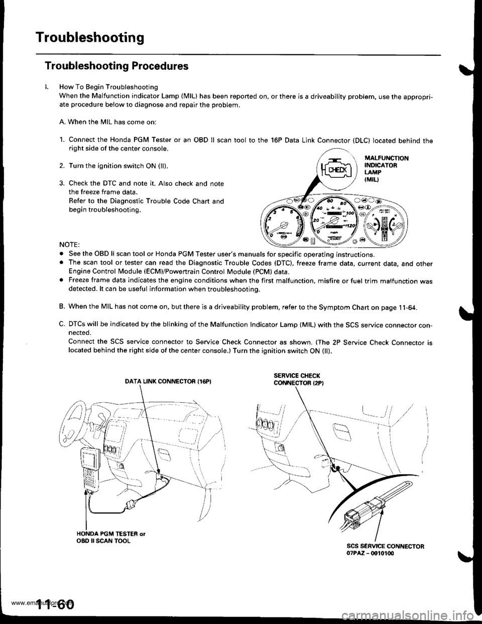
1. Connect the Honda PGM Tester or an OBD Il scan tool to the 16P Data Link Connector (DLC) located behind theright side of the center console.
Turn the ignition switch ON (ll).
Check the DTC and note it. Also check and note
the freeze frame data.
Refer to the Diagnostic Trouble Code Chart and
begin troubleshooting.
NOTE:
. SeetheOBDll scan tool or Honda PGM Tester user's manuals for specific operating instructions.. The scan tool or tester can read the Diagnostic Trouble Codes (DTC), freeze frame data, current data, and otherEngine Control Module (ECM}/Powertrain Control Module (PCM) data.. Freeze frame data indicates the engine conditions when the first malfunction, misfire or fuel trim malfunction wasdetected. lt can be useful information when troubleshootino.
B. When the MIL has not come on, but there is a driveability problem, refer to the Symptom Chart on page 11-64.
C. DTCs will be indicated by the blinking of the Malfunction Indicator Lamp {MlL) with the SCS service connector con-nected.
Connect the SCS service connector to Service Check Connector as shown. {The 2P Service Check Connecror rslocated behind the right side of the center console.) Turn the ignition switch ON 0l).
DATA LINK CONNECTOR I16PI
1 1-60
www.emanualpro.com
Page 982 of 1395
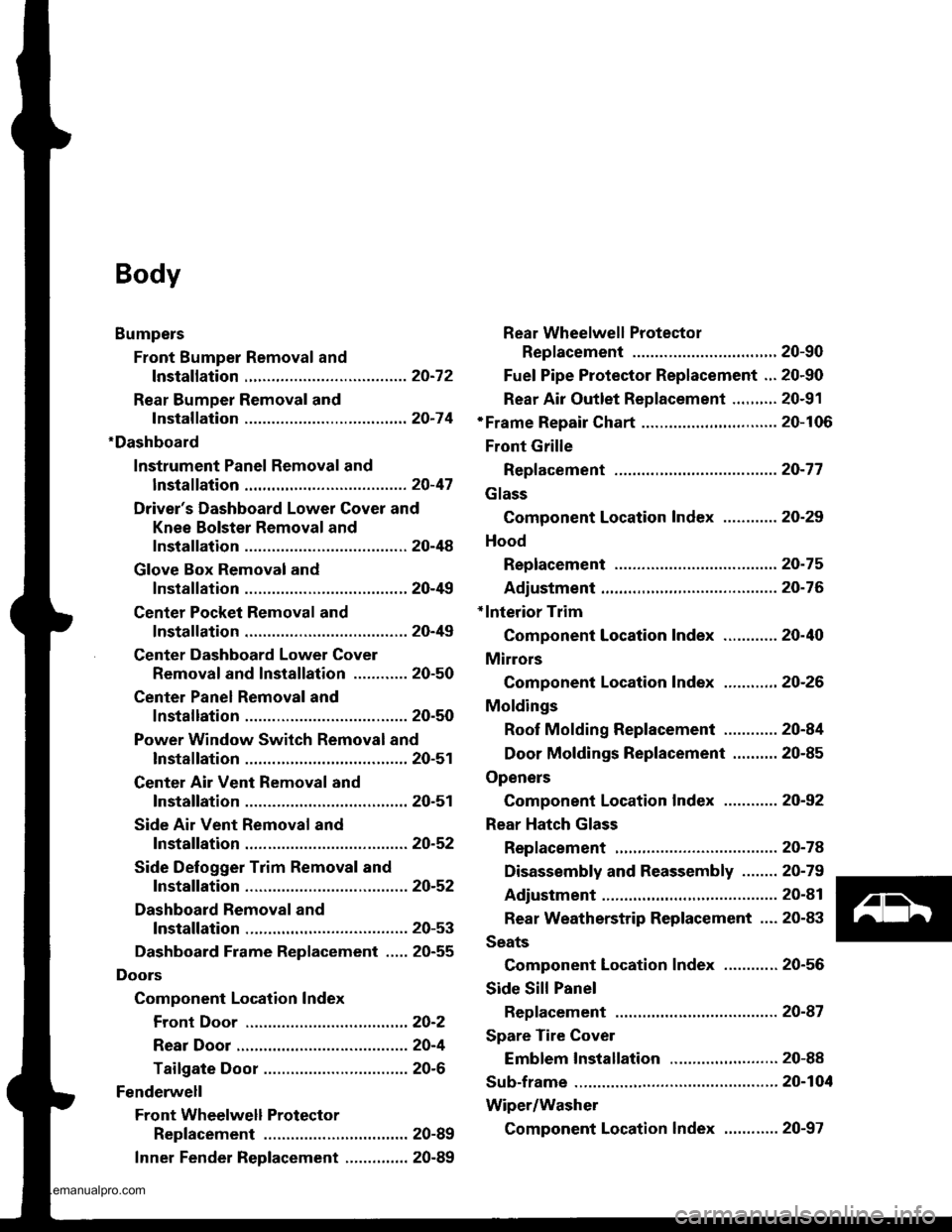
Body
Bumpers
Front Bumper Removal and
fnstaflation .........20-72
Rear Bumper Removal and
fnstaflation .........20-74
'Dashboard
lnstrument Panel Removal and
lnstallation .........20-47
Driver's Dashboard Lower Cover and
Knee Bolster Removal and
Installation .........20-48
Glove Box Removal and
lnstallation .........20-49
Center Pocket Removal and
lnstallation .........20-49
Center Dashboard Lower Cover
Removal and lnstallation ............ 20-50
Center Panel Removal and
lnstallation .........20-50
Power Window Switch Removal and
lnstallation .........20-51
Center Air Vent Removal and
lnstallation .........20-51
Side Air Vent Removal and
fnstallation .........20-52
Side Defogger Trim Removal and
fnstallation .........20-52
Dashboard Removal and
lnstallation .........20-53
Dashboard Frame Replacement ..... 20-55
Doors
Component Location Index
Front Door ,,...,,,,20-2
Rear Door ...........20-4
Tailgate Door ................................ 20-6
Fenderwell
Front Wheelwell Protector
Replacement .....20-89
Inner Fender Replacement .,.....,.,.... 20-89
Rear Wheelwell Protectol
Replacement .....20-90
Fuel Pipe Protector Replacement ... 20-90
Rear Air Outlet Replacement .......... 20-91
*Frame Repair Chart .............................. 20-106
Front Grille
Repf acement .........20-77
Glass
Component Location Index ............ 20-29
Hood
Replacement ......,,,20-75
Adjustment ............20-76
*lnterior Trim
Component Location Index ............ 20-40
Mirrors
Component Location Index .........,,, 20-26
Moldings
Roof Molding Replacement ............ 20-84
Door Moldings Replacement .......... 20-85
Openers
Component Location Index ............ 20-92
Rear Hatch Glass
Replacement .........20-74
Disassembly and Reassembly ........ 20-79
Adiustment ............20-81
Rear Weatherstrip Replacement .... 20-83
Seats
Component Location Index ............ 20-56
Side Sill Panel
Repfacement .........20-87
Spare Tire Cover
Emblem Installation ........................ 20-88
Sub-frame ..................20-104
Wiper/Washer
Component Location lndex ,,,,,....... 20-97
www.emanualpro.com
Page 997 of 1395
Doors
License Plate Trim Removal and
Installation
CAUTION: Put on gloves to prolest your hands.
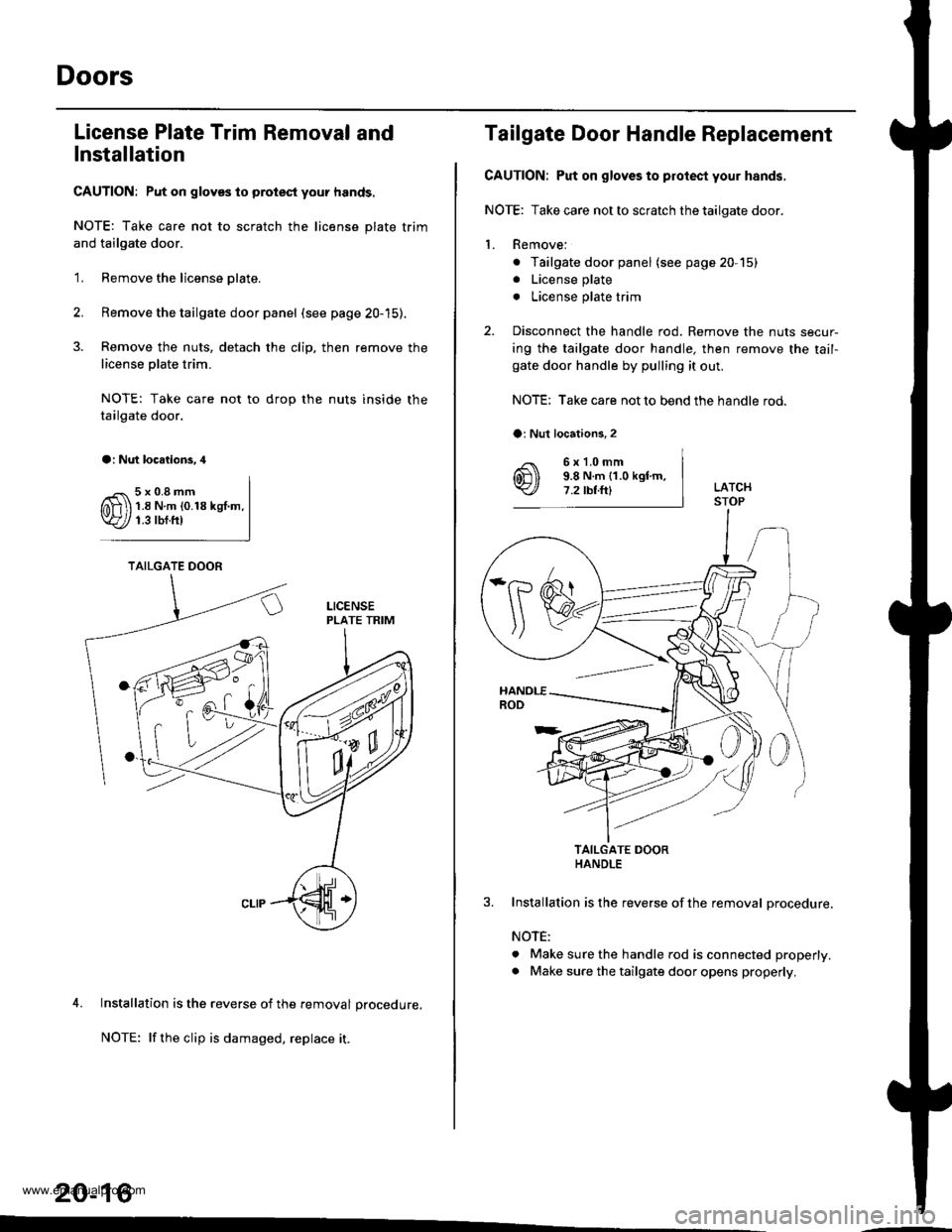
NOTE: Take care not to scratch the license plate trim
and tailgate door.
'1. Remove the license olate.
2. Remove the tailgate door panel (see page 20-15).
3. Remove the nuts, detach the clip, then remove the
license olate trim.
NOTE: Take care not to drop the nuts inside the
tailgate door.
a: Nut loc.lions.4
5x0.8mm1.8Nm(0.18kgt.m.1.3 rbf.ft)
4. Installation is the reverse of the removal procedure.
NOTE: lf the clip is damaged, replace it.
20-16
TAILGATE DOOR
Tailgate Door Handle Replacement
CAUTION; Put on gloves to protecl your hands,
NOTE: Take care not to scratch the tailgate door.
1. Remove:
. Tailgate door panel (see page 20,15)
. License plate
. License plate trim
2. Disconnect the handle rod. Remove the nuts secur-
ing the tailgate door handle, then remove the tail-gate door handle by pulling it out.
NOTE: Take care not to bend the handle rod.
6x1.0mm9.8 N.m {1.0 kgtm,7.2 rbtft)
TAILGATE DOORHANDLE
Installation is the reverse of the removal procedure.
NOTE:
. Make sure the handle rod is connected properly.
. Make sure the tailgate door opens propedy.
a: Nut locations,2
,Is
www.emanualpro.com
Page 1011 of 1395
Glass
Windshield Replacement
CAUTION:
. Put on gloves to protect your hands.
. Use seat covers to avoid damaging any surfaces.
1. To remove the windshield, first remove the:
. Rearview mirror (see page 20-28)
. Sunvisors and holders (see page 20-44l'
. Ceiling light (see section 23)
. Grab handle (see page 20-44)
. Front door trim (see page 20-41)
. Front pillar trim (see page 20-41)
. Windshield wiper arms and cowl cover (see page
20-98)
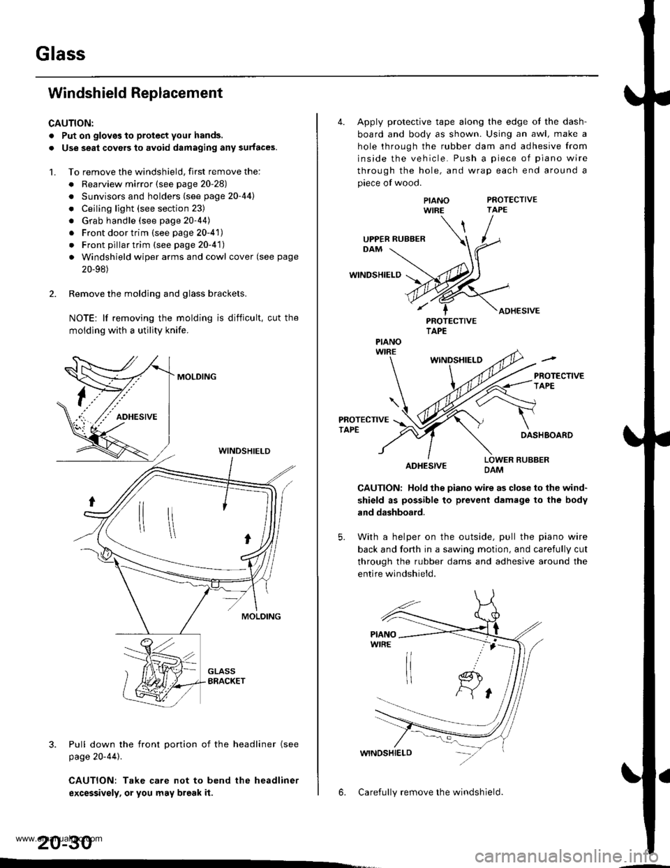
2. Remove the molding and glass brackets.
NOTE: lf removing the molding is difficult, cut the
moldlng with a utility knife.
MOLDING
3. Pull down the front Dortion of the headliner (see
page 20-44).
CAUTION: Take care not to bend the headliner
excessivsly, or you may break it.
WINDSHIELD
20-30
4. Apply protective tape along the edge ot the dash-
board and body as shown. Using an awl, make a
hole through the rubber dam and adhesive from
inside the vehicle. Push a piece of piano wire
through the hole, and wrap each end around a
piece of wood.
PROTECTIVETAPE
WINDSHIELD
ADHESIVE
PIANOWIRE
PROTECTIVETAPE
WINDSHIELO
PROTECTIVETAPEDASHBOARD
ADHESIVELOWER RUBBERDAM
CAUTION: Hold the piano wire as close to the wind-
shield as possible to prevent damage to the body
and dashboard.
5. With a helper on the outside, pull the piano wire
back and fo(h in a sawing motion, and carefully cut
through the rubber dams and adhesive around the
entire windshield.
6. Carefully remove the windshield.
UPPER RUBBER
PIANO
www.emanualpro.com
Page 1016 of 1395
22.
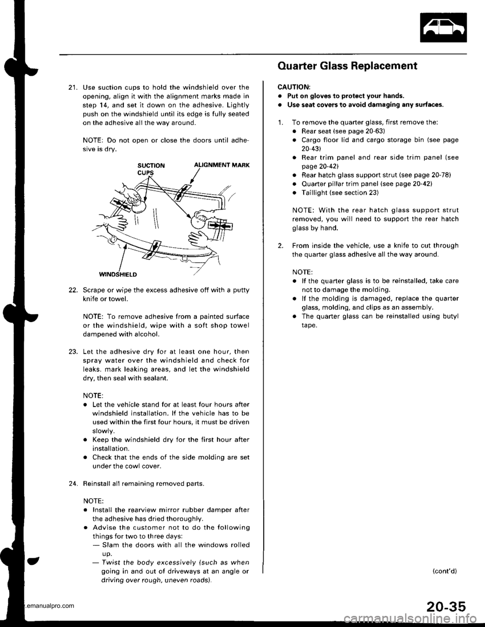
21. Use suction cups to hold the windshield over the
opening, align it with the alignment marks made in
step 14, and set it down on the adhesive. Ljghtly
push on the windshield until its edge is fully seated
on the adhesive all the way around.
NOTEr Do not open or close the doors until adhe-
sive is dry.
SUCTTON ALIGNMENT MARK
Scrape or wipe the excess adhesive off with a putty
knife or towel.
NOTE: To remove adhesive from a painted surface
or the windshield, wipe with a soft shop towel
dampened with alcohol.
Let the adhesive dry for at least one hour, then
spray water over the windshield and check for
leaks. mark leaking areas, and let the windshield
dry, then seal with sealant.
NOTE:
. Let the vehicle stand for at least four hours after
windshield installation. lf the vehicle has to be
used within the first four hours, it must be driven
. Keep the windshield dry for the first hour after
installation.
. Check that the ends of the side molding are set
under the cowl cover.
Reinstall all remaining removed parts.
NOTE:
. Install the rearview mirror rubber damper after
the adhesive has dried thoroughl,.
. Advise the customer not to do the following
things for two to three days:- Slam the doors with all the windows rolled
up.- Twist the body excess,vely {such as when
going in and out of driveways at an angle or
driving over rough. uneven roads).
24.
Ouarter Glass Replacement
CAUTION:
. Put on gloves to prot€ct your hands.
. Use seat covers to avoid damaging any surfaces.
1. To remove the quarter glass, first remove the:
. Rear seat (see page 20-63)
. Cargo floor lid and cargo storage bin (see page
20 431
. Rear trim panel and rear side trim panel (see
page 20-421
. Rear hatch glass support strut (see page 20-78)
. Ouarter pillar trim panel (see page20-421
. Taillight (see section 23)
NOTE: With the rear hatch glass support strut
removed, you will need to support the rear hatch
glass by hand.
2. From inside the vehicle, use a knife to cut through
the quarter glass adhesive all the way around.
NOTE:
. lf the quaner glass is to be reinstalled, take care
not to damage the molding.
. lf the molding is damaged. replace the quarter
glass, molding, and clips as an assembly.
. The quarter glass can be reinstalled using butyl
tape.
(cont'd)
20-35
www.emanualpro.com
Page 1021 of 1395
lnterior Trim
20-40
CARGO FRONTSPACER(see page 20 43)
FRONT PILLARTRIM(see page 20-41)
TRUNK FLOOREXTENSION(see page 20 43)
HEADLINERRemoval and lnstallation,page 20-44
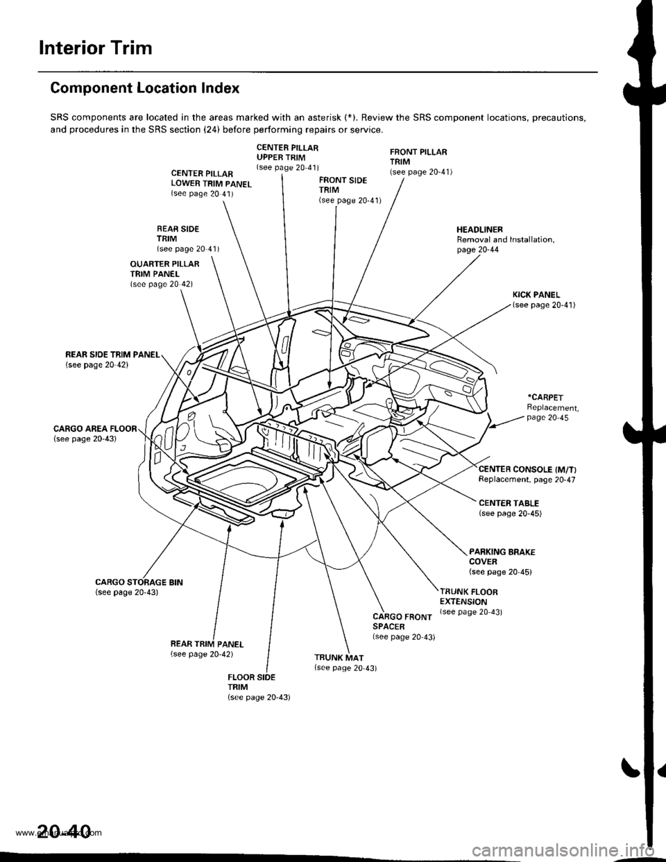
Component Location Index
SRS components are located in the areas marked with an asterisk (*). Review the SRS component locations, precautions,
and procedures in the SRS section (24) before performing repairs or service.
CENTER PILLARUPPER TRIM(see page 20 41)CENTER PILLARLOWER TRIM PANEL(see page 20 41)
FRONT SIDETRIM(see page 20-41)
BEAR SIDETEIM(see page 20'41)
OUARTER PILLARTRIM PANEL(see page 20 42)
*CARPET
Replacement,page 20 45
CENTER CONSOLE IM/T}Replacement, page 20-47
CENTEN TABLE(see page 20-45)
PARKING BRAKECOVER(see page 20-45)
TRIM
www.emanualpro.com
Page 1022 of 1395
Removal and Installation
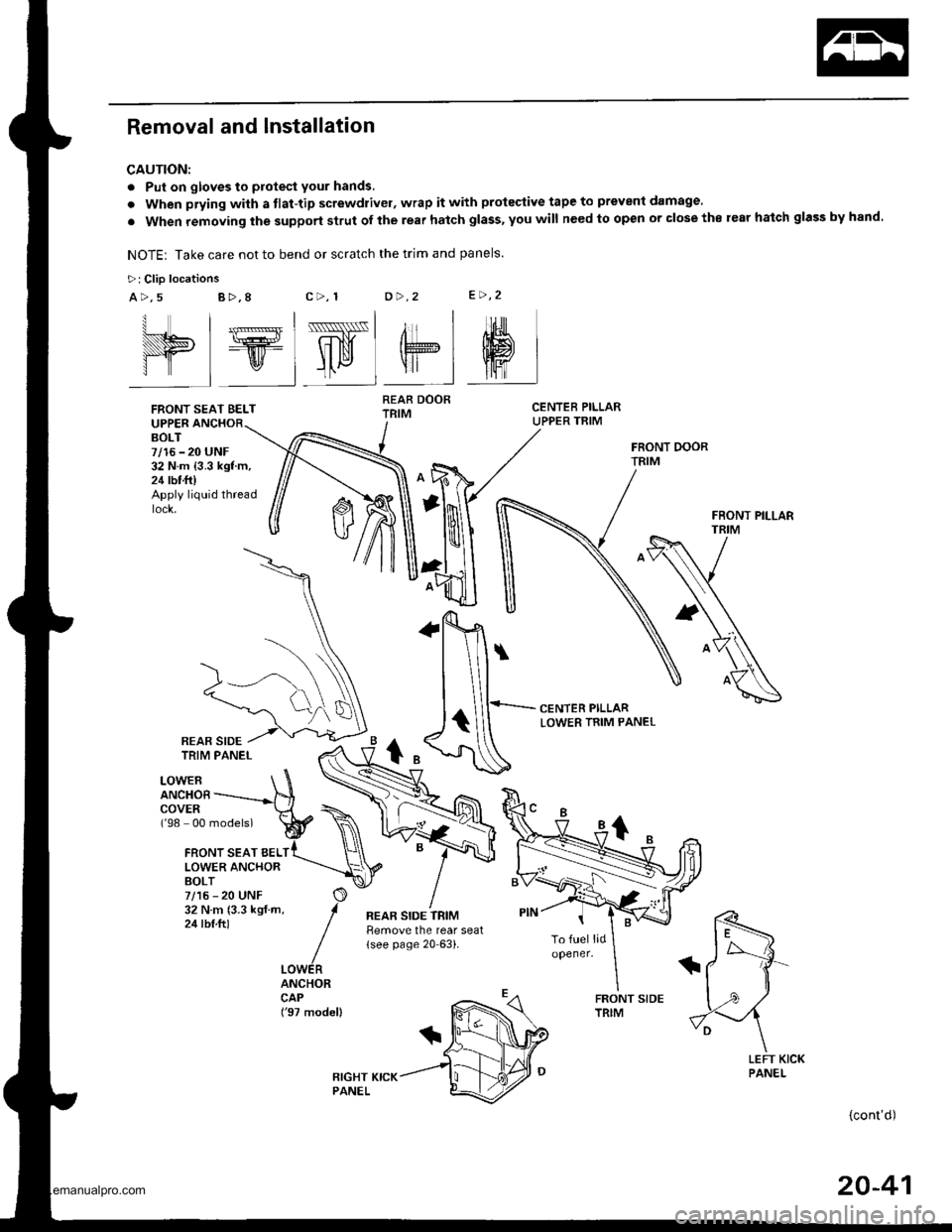
CAUTION:
. Put on gloves to protect your hands,
. When prying with a tlat-tip screwdrivel, wrap it with protective tape to prevent damage.
. When removing the support strut of the rear hatch glass, you will need to open or close the rear hatch glass by hand.
NOTE: Take care not to bend or scratch the trim and panels.
>: Clio locations
a>,5c>, 1o>.2e>,2B >,8
UPPERBOLT7/16 - 20 UNF32 N.m {3.3 kgf.m,24 rbt.ft)Apply liquid thread
CENTER PILLARLOWER TRIM PANEL
LOWERANCHOBCOVER('98 00 models)
{cont'd)
I l_lss-l , | 'rrl
elElw"lel sl
FRONT SEAT BELT
FRONT SEAT BELLOWER ANCHORBOLT7/15 - 20 UNF32Nm(3.3kgf.m,24 tbt.ftl
ANCHORCAP('97 model)
REAR DOORTRIM
REAR SIDE TRIMtlemove the rear seat(see page 20 63).
REAR SIDE
20-41
www.emanualpro.com
Page 1024 of 1395
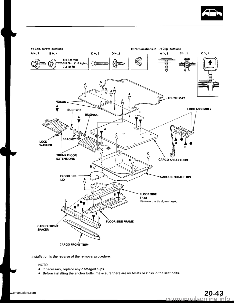
>: Bolt, screw locations
a>,3 B>,4
o: Nut locations, 2 >: Clip locations
TRUNK MAT
CARGO STORAGE BIN
/ rr. 6xl.Omm I
m)b D lbe.8 Nm r1.o ksnm.l-
c>,2 0>,2 A>,8 B>,r
| .€ | r- -I At I tl1|r' t I l���'---llH- | E
GlrrIIITTpl 0pE l w I l--Tr@HPv | | v I vv
LOCK ASSEMBLY
TRUNK FLOOREXTENSIONS
FLOOR SrO€LID
FLOOR SIDE FRAME
CARGO FRONT TRIM
Insta,lation is the reverse of the removal procedure.
NOTE:
. lf necessary, replace any damaged clips.
r Before installing the anchor bolts, make sure there are no twists or kinks in the seat belts.
BUSHING
l^IV
>ilv '%L
"ro"*i*
CARGO AREA FLOOR
l*,hl
20-43
www.emanualpro.com