Page 1025 of 1395

lnterior Trim
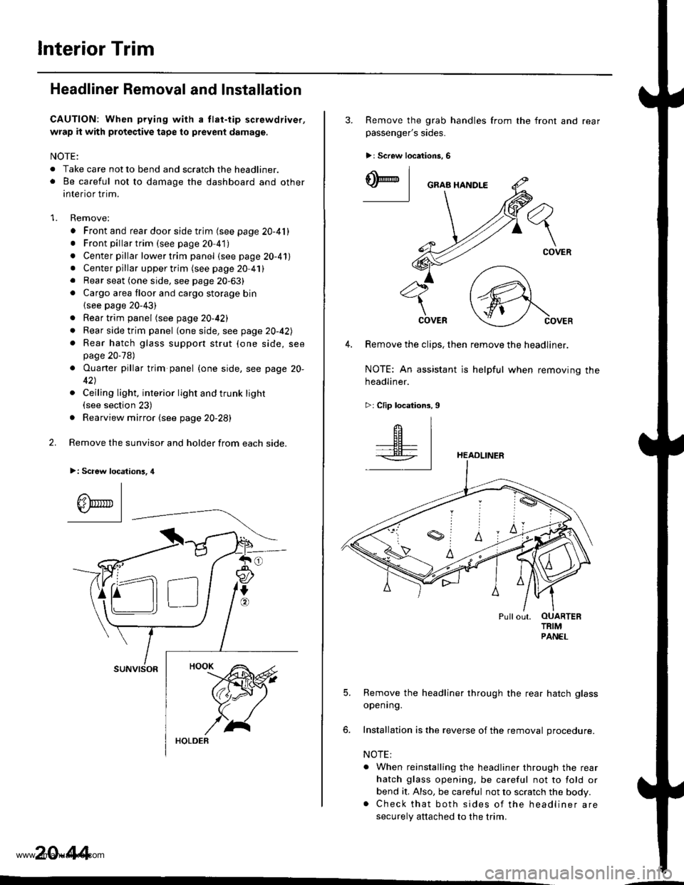
Headliner Removal and Installation
CAUTION: When prying with a tlat-tip screwdriver,
wrap it with protective tape to prevent damage.
NOTE:
. Take care not to bend and scratch the headliner.o Be careful not to damage the dashboard and other
interior trim.
1. Remove:
. Front and rear door side trim (see page 20-41). Front pillartrim (see page 20-41)
. Center pillar lower trim panel (see page 20-41). Center pillar upper trim (see page 20 41). Rear seat (one side, see page 20-63). Cargo area floor and cargo storage bin
{see page 20-43)
. Rear trim panel (see page 20-421
. Rear side trim panel (oneside, see page 20-42l,
. Rear hatch glass support strut (one side, seepage 20-78)
. Ouaner pillar trim panel {one side, see page 20-
42)
. Ceiling light, interior light and trunk light(see section 23)
. Rearview mirror (see page 20-28)
2. Remove the sunvisor and holder from each side.
>: Scaew location3, 4
I
A\"r- |Yr* || -
suNvtsoR
20-44
3. Remove the grab handles from
passenger's sides.
>r Screw locations, 6
the front and rear
ry_l
COVER
4. Remove the clips, then remove the headliner.
NOTE: An assistant is helpful when removing the
headliner.
>: Clip locations,9
HEADLINER
Pullout. OUARTERTRIMPANEL
5. Remove the headliner through the rear hatch glass
openrng.
6. Installation is the reverse of the removal procedure.
NOTE:
. When reinstalling the headliner through the rear
hatch glass opening, be careful not to fold or
bend it, Also, be careful not to scratch the body.. Check that both sides of the headliner are
securely attached to the trim.
www.emanualpro.com
Page 1026 of 1395
Carpet Replacement
SRS comDonents are located in this area. Review the SRS
component locations, precautions, and procedures in the
SRS section {24) before performing repairs or service.
CAUTION: Put on gloves to protect your hands.
Remove:
. Front seat (see page 20-571
. Rear seat (see page 20 63)
. Kick panel (see page 20-41)
. Center pillar lower trim panel (see page 20 41)
. Front side trim {see page 20-41)
. Lower console cover 1A,/T model, see page 20-49)
. Center console (lM/T model, see page 2o-47)
Remove the footrest.
>: Eolt locaiions,2
2.
'1.
6x1.0mm9.8 N.m {1.0 kgf.m,7 .2 tbt.ttt
FOOTREST
3. Remove the parking brake cover.
>: Screw locations,2
6bo" I"l
4. Remove the center table and table frame bracket.
>: Bolt locations, 4a: Nut locations, 4
>: Clip locations, 4
ill
,l
8 x 1.25 mm22N.m l2.2kgl.n,16 tbt ft)
8 x 1.25 mm22 N.m 12.2 kgf.m,16 tbtfrl
Forwaad
TABLE FRAMEBRACKET
{cont'd)
CENTER TABLE
COVER
20-45
www.emanualpro.com
Page 1033 of 1395

Dashboard
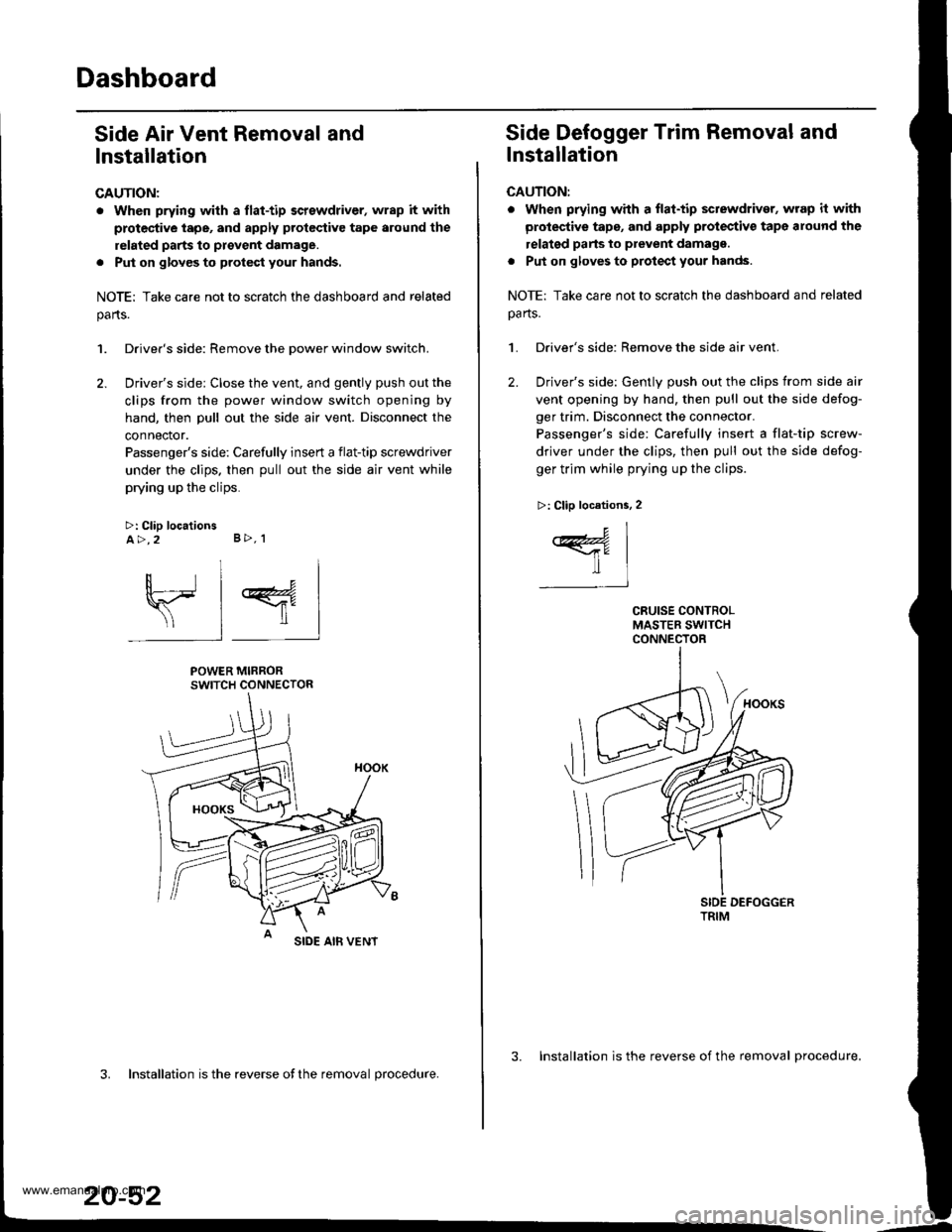
Side Air Vent Removal and
lnstallation
CAUTION:
. When prying with a flat-tip screwdriver, wrap it with
protec'tive tape, and apply protcctive tape around the
related parts to provent damage.
. Put on glov€s to protect your hands.
NOTE: Take care not to scratch the dashboard and related
parts.
1. Driver's side: Remove the Dower window switch.
2. Driver's side: Close the vent, and gently push out the
clips from the power window switch opening by
hand, then pull out the side air vent. Disconnect the
connector.
Passenger's side: Carefully insert a flat-tip screwdriver
under the clips. then pull out the side air vent while
prying up the clips.
>: Clip locationsA>,2 B>, 1
sl 4
POWER MIRRORSWITCH CONNECTOR
SIDE AIB VENT
3. Installation is the reverse ofthe removal procedure.
20-52
3. Installation is the reverse of the removal procedure.
Side Defogger Trim Removal and
lnstallation
CAUTION:
. when prying whh a flat-tip sctewdriver, wrap it with
protective tape, and apply protectiv€ tape around the
relatgd parts to prevent damagg.
. Put on gloves to protect your hands.
NOTE: Take care not to scratch the dashboard and related
oa rts.
1. Driver's side: Remove the side air vent.
2. Driver's side: Gently push out the clips from side air
vent opening by hand, then pull out the side defog-
ger trim. Disconnect the connector.
Passenger's side: Carefully insert a flat-tip screw-
driver under the clips, then pull out the side defog-
ger trim while prying up the clips.
>: Clip locations, 2
c1
ffil-t
TRIM
www.emanualpro.com
Page 1034 of 1395

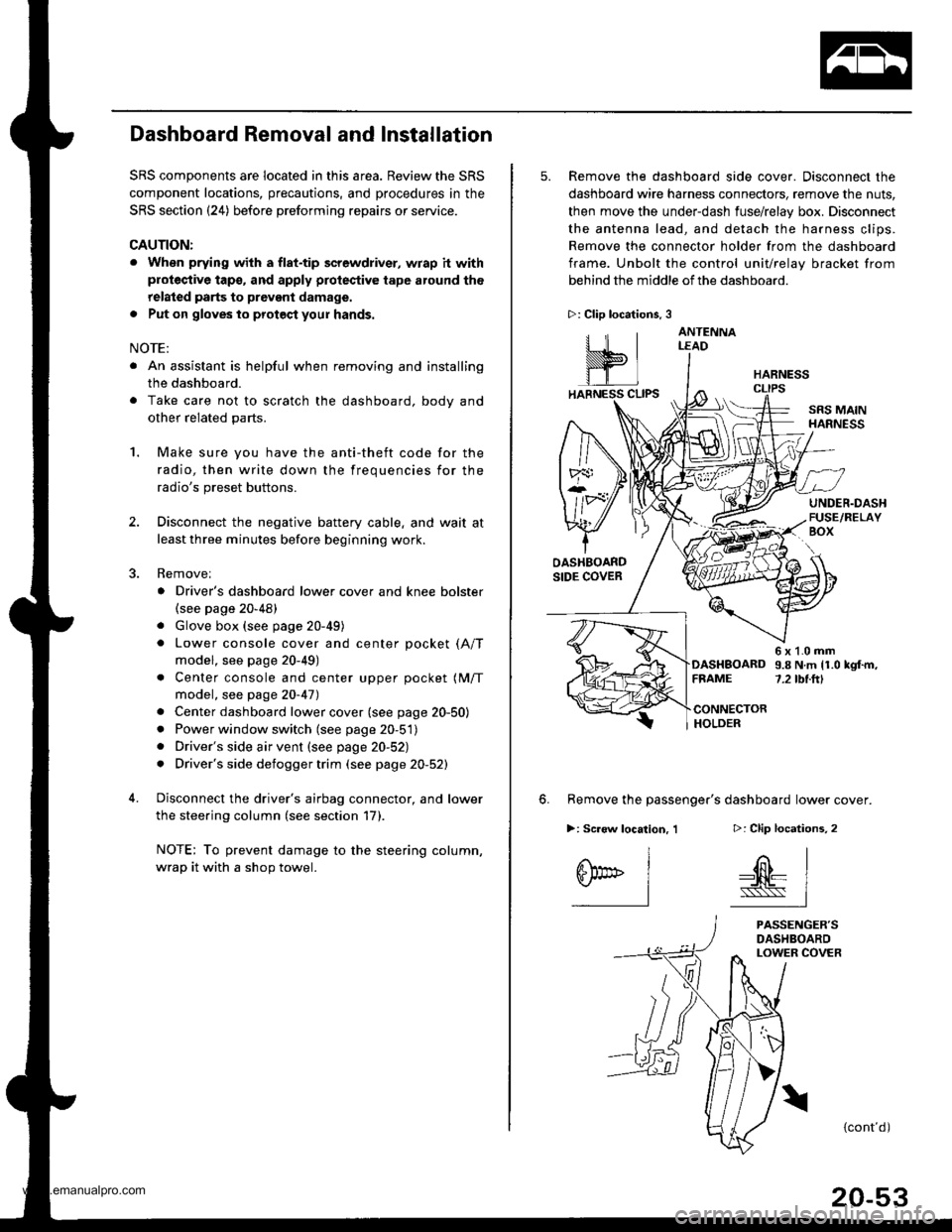
Dashboard Removal and Installation
SRS components are located in this area. Review the SRS
component locations, precautions, and procedures in the
SRS section {24) before preforming repairs or service.
CAUTION:
. When prying with a flat-tip screwdriver, wrap h withprotective tap€, and apply protective tape around the
related parts to prevgnt damage.
. Put on gloves to prot€ct your hands.
NOTE:
. An assistant is helpful when removing and installing
the dashboard.
. Take care not to scratch the dashboard, bodv and
other related parts.
1.Make sure you have the anti-theft code for the
radio, then write down the frequencies for the
radio's preset buttons.
Disconnect the negative battery cable. and wait at
least three minutes before beginning work.
Removei
a Driver's dashboard lower cover and knee bolster(see page 20-48)
. Glove box (see page 20-49)
. Lower console cover and center pocket (A/T
model, see page 20-49)
. Center console and center upper pocket (M/T
model, see page 20-47)
. Center dashboard lower cover (see page 20-50)
. Power window switch (see page 20-51)
. Driver's side air vent (see page 20-52)
. Driver's side defogger trim (see page 20-52)
Disconnect the driver's airbag connector, and lower
the steering column (see section 17)
NOTE: To prevent damage to the steering column,
wrap it with a shop towel.
2.
5. Remove the dashboard side cover. Disconnect the
dashboard wire harness connectors, remove the nuts,
then move the under-dash fuse/relay box. Disconnect
the antenna lead, and detach the harness clips.
Remove the connector holder from the dashboard
frame. Unbolt the control unit/relay bracket from
behind the middle of the dashboard.
HARNESS
6. Remove the passenger's dashboard lower cover.
D: Clip locations,
nl
-$t- Issj
I
ANTENNALEAD
>: Clip locations.
rttl
slllll
>: Scr€w location, 1
I
SF:oo I-l
SRS MAINHARNESS
UNDER.DASHFUSE/RELAYBOX
OASHBOARDSIDE COVER
6x1.0mm9.8Nm11.0kgf.m,7.2tbt.ftlDASHBOARDFFAME
CONNECTORHOLDER
PASSENGER'SDASHBOARDLOWER COVER
{cont'd)
www.emanualpro.com
Page 1061 of 1395
Rear Hatch Glass
l,_ | r\
wl:
f\ALIGNMENT HARNESSMARK TRIM
Disassembly and Reassembly (cont'dl
NOTE: Before installing the rear spoiler spacer, harness trim. caution label, real time 4WD emblem and glass protector,
clean the rear hatch glass bonding surface with a sponge dampened in alcohol.
>: Alignment mark locatioosA>
ALIGNMENTMARK
A Center line
lnside:
Outside:Centor line
REAR SPOILERSPACER{'97 98 models)
SPOILERREARSPACEBSSPACERS('99 00 models){'99 00 models)
20-80
REAR SPOILER SPACER
ooo O
www.emanualpro.com
Page 1075 of 1395
Openers
Fuel Fill Door Opener Cable Replacement
NOTE:
. When removing the clips, use a clip remover.
. Take care not to bend the opener cable.
Remove the following parts, then pull the carpet back, as necessary (see page 20-45),
a
>: Clip locationsA>,6 B>, 1
a
a
FUEL FILL OOOR LATCH(see page 20-96)
Kick panel (left side. see page 20-41)
Center pillar lower trim panel (left side, see page 20-
41)
Front side trim (left side, see page 20-41)
Rear seat (left side, see page 20-63)
Cargo area floor and cargo storage bin (see page
43)
Rear trim panel {see page 20-42)
Rear side trim panel (left side, see page 20-421
Rear side trim (left side, see page 20-41)
FUEL FILL DOOR OPENER
{see page 20-96)
20-
c>,1
@lRlg
Installation is the reverse of the removal procedure.
NOTE:
. lf necessary, replace any damaged clips.
r Make sure fuel fill door opener cable is routed and connected properly.
. Make sure the fuel fill dooropens properly.
www.emanualpro.com
Page 1077 of 1395
Openers
Fuel Fill Door Opener Replacement
NOTE: Take care not to bend the opener cable.
Remove the left front side trim (see page 20-41).
>: Bolt locstions.2
5x1.0mm9.8 N.m (1.0 kgf.m,7.2 tbt.ftl
FUEL FILL DOOROPENER CABLE(see page 20-94)
Installation is the reverse of the removal procedure.
NOTE:
. Make sure the opener cable is connected properly.
. Make sure the fuel fill door opens properly,
20-96
Fuel Fill Door Latch Reolacement
NOTE: Take care not to bend the opener cable.
Remove the rear speaker cover and rear speaker from
the left rear side trim panel (see page 20-42).
>: Boh locdions, 2
6x1.0mm9.8 N.m (1.0 kgf.m,7.2 tbf.ft)FUEL FILL DOOR LATCH
FUEL FILL DOORAfter installing, check fora flush fit with the body.
CAELE(see Page
LATCH
DOOR OPENER
20,94)
FUEL
FUEL FILLRemove the fuel fill door latchby turning it 90'
Installation is the reverse of the removal procedure.
NOTE: Make sure the fuel fill door opens properly
and locks securely.
www.emanualpro.com
Page 1082 of 1395

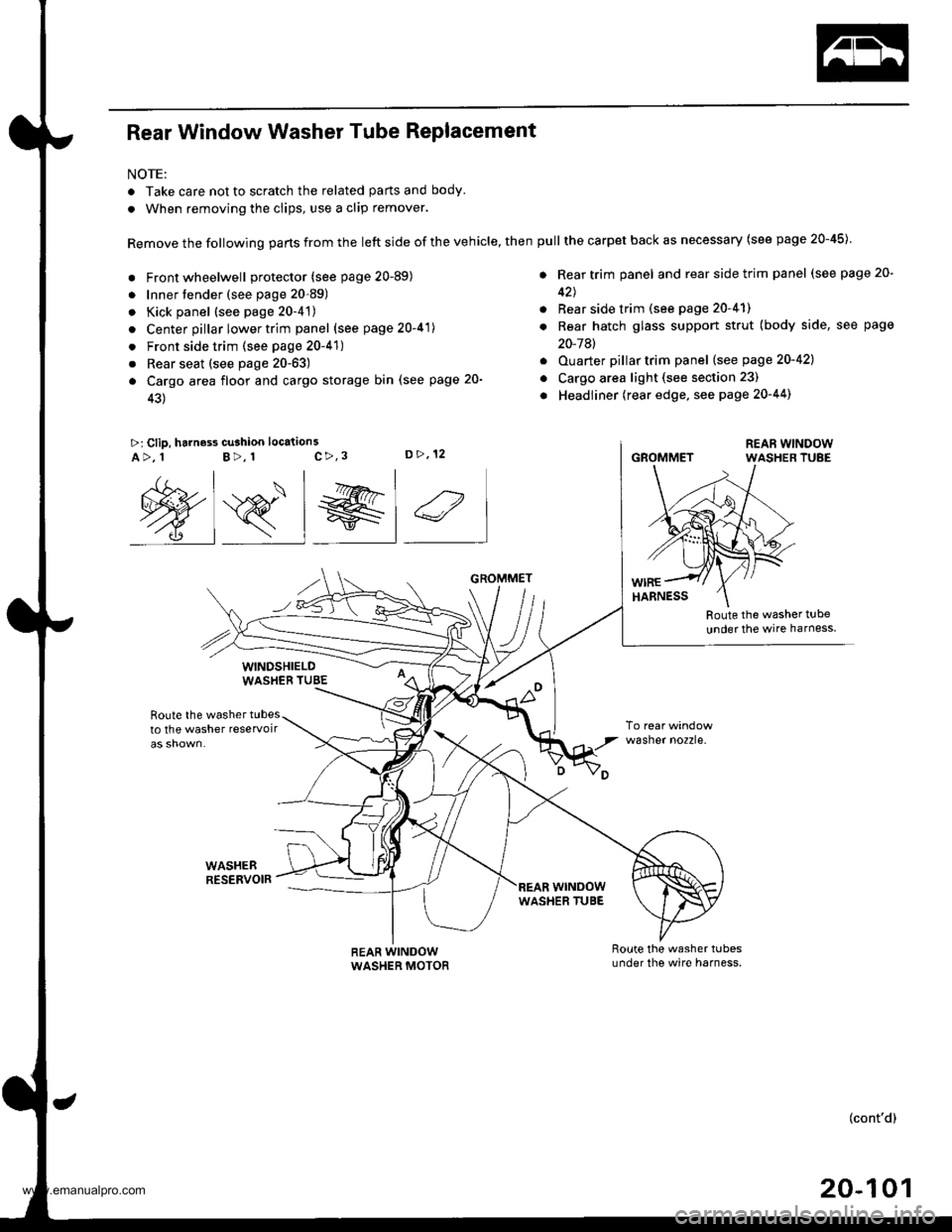
Rear Window Washer Tube Replacement
NOTE:
. Take care not to scratch the related parts and body.
. When removing the clips, use a clip remover.
Remove the following parts from the left side of the vehicle, then
. Front wheelwell protector (see page 20-89)
. Innertender (see page 20-89)
. Kick panel (see page 20-4't)
. Center pillar lower trim panel (see page 20-41)
. Front side trim (see page 20-41)
. Rear seat (see page 20-63)
a Cargo area floor and cargo storage bin (see page 20-
43)
>: Clip, harness cu3hion location3c>,3D>,12A>, 1B>, 1
Route the washer t!be
under the wire harness
Route the washer tubesto the washer reservoir
WASHEBRESERVOIR
wasner no2zre.
@s_l el 4
WINDSHIELDWASHEB TUBE
REAR WINDOWWASHER MOTOR
GROMMET
wrNoowWASHER TUBE
pull the carpet back as necessary (see page 20-45)
. Rear trim panel and rear side trim panel (see page 20-
42J
. Rear side trim (see page 20-41)
. Rear hatch glass support strut (body side, see page
20-7Al
. Ouarter pillartrim panel (see page 20-421
o Cargo area light (see section 23)
. Headliner (rear edge, see page 20-44)
GROMMET
(cont'd)
20-101
www.emanualpro.com