1997 HONDA CR-V Install
[x] Cancel search: InstallPage 13 of 1395
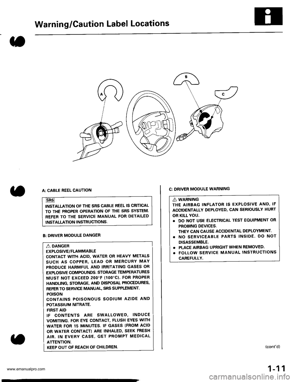
Warning/Caution Label Locations
C: DRIVER MODULE WARNING
A WARNING
THE AIREAG INFLATOR IS EXPLOSIVE AND, IF
ACCIDENTALLY DEPLOYED, CAN SERIOUSLY HURT
OR KILL YOU.
. DO NOT USE ELECTRICAL TEST EOUIPMENT OR
PROBING DEVICES.
THEY CAN CAUSE ACCIDENTAL DEPLOYMENT.
. NO SERVTCEABLE PARTS lNSlDE. DO NOT
DISASSEMBLE.
. PLACE AIRBAG UPRIGHT WHEN REMOVED
. FOLLOW SERVICE MANUAL INSTRUCTIONS
CAREFULLY.
A: CABLE REEL CAUTION
TNSTALLATION OF THE SRS CABLE REEL IS CRITICAL
TO THE PBOPER OPERATION OF THE SRS SYSTEM.
REFER TO THE SERVICE MANUAL FOR DETAILED
INSTALLATION INSTRUCTIONS.
(cont'd)
1-11
B: DRIVER MODULE DANGER
A DANGER
EXPLOSIVE/FLAMMABLE
CONTACT WITH ACID, WATER OR HEAVY METALS
SUCH AS COPPER, LEAD OR MERCURY MAY
PRODUCE HARMFUL AND IRRITATING GASES OR
EXPLOSIVE COMPOUNDS. STOMGE TEM PERATURES
MUST NOT EXCEED 2OO"F {1OO'C}. FOR PROPER
HANDUNG, STORAGE, AND DISPOSAL PROCEDURES.
REFER TO SERVICE MANUAI- SRS SUPPI.EMENT,
POTSON
CONTAINS POISONOUS SODIUM AZIDE AND
POTASSIUM NITRATE.
FIRST AID
tF CONTENTS ARE SWALLOWED, INDUCE
VOMITING. FOR EYE CONTACT, FLUSH EYES WITH
WATER FOR 15 MINUTES. IF GASES IFROM ACID
OR WATER CONTACTI ARE INHALED, SEEK FRESH
AIR. IN EVERY CASE, GET PROMPT MEDICAL
ATTENTION.
KEEP OUT OF REACH OF CHILDREN
www.emanualpro.com
Page 15 of 1395
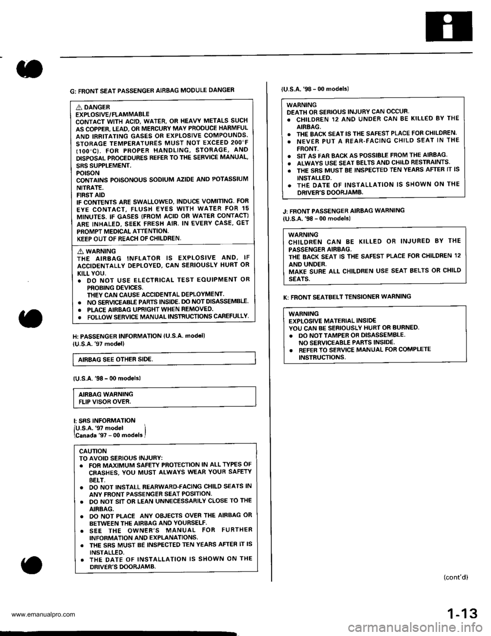
G: FRONT SEAT PASSENGER AIRBAG MODULE DANGEN
A DANGEREXPLOSIVE/FLAMMABLECONTACT WITH ACID, WATER. OR I{EAVY METALS SUCH
AS COPPER. T.EAD. OR MERCURY MAY PRODUCE HARMFUL
AND IRRITATING GASES OR EXPLOSIVE COMPOUNDS.
STORAGE TEMPERATURES MUST NOT EXCEED 2OO"F
IlOO'C). FOR PROPER HANDLING, STORAGE, AND
DISPOSAL PROCEDURES REFER TO THE SERVICE MANUAL,
SRS SUPPLEMENT.POTSONCONTAINS POTSONOUS SODIUM AZIDE ANO POTASSIUM
NITRATE.FIRST AIDIF CONTENTS ARE SWALLOWED, INDUCE VOMITING. FOR
EYE CONTACT, FLUSH EYES WITH WATER FOR 15
MINUTES. IF GASES (FROM ACID OR WATEN CONTACT)
ARE INHALEO. SEEK FRESH AIR. IN EVERY CASE, GET
PROMPT MEDICAL ATTENTION.KEEP OUT OF REACH OF CHILDREN.
A WARNINGTHE AIRBAG INFLATOR IS EXPLOSIVE AND, IF
ACCIDENTALLY DEPLOYED, CAN SERIOUSLY HURT OR
KILL YOU.. DO NOT USE ELECTRICAL TEST EOUIPMENT OR
PROBING DEVICES,THEY CAN CAUSE ACCIDENTAL DEPLOYMENT.. NO SERVICEABI-E PARTS lNSlDE. DO NOT DISASSEMBII.
. PLACE AIRBAG UPRIGHT WHEN REMOVEO.
. FOLLOW SERVIC€ MANUAL INSTRUCTIONS CAREFULLY
H: PASSENGER INFORMATION lU S.A. modell
{U.S.A.'97 model}
AIEBAG SEE OTHER SIDE,
{U.S.A.'98 - 00 modelsl
AIRBAG WARNINGFLIP VISOR OVER.
l: SRS INFORMATION
lU.s.A.'97 model ilcanada '97 - 00 mod€ls I
CAUTIONTO AVOID SERIOUS INJURY:. FOR MAXIMUM SAFEW PROTECTION lN ALL TYPES OF
CRASHES, YOU MUST ALWAYS WEAR YOUR SAFETY
8ELT.o OO NOT INSTALL REARWARD-FACING CHILO SEATS lN
ANY FRONT PASSENGER SEAT POSITION.. DO NOT SIT OR LEAN UNNECESSARILY CLOSE TO THE
AIRBAG.. DO NOT PLACE ANY OBJECTS OVER THE AIRBAG OR
BETWEEN THE AIRBAG AND YOURSELF.. SEE THE OWNER'S MANUAL FOR FURTHER
INFORMATION AND EXPLANATIONS. THE SRS MUST BE INSPECTED TEN YEARS AFTER lT lS
INSTALLED.. THE DATE OF INSTALLATION lS SHOWN ON THE
DRIVER'S DOORJAMB.
lU.S.A.'98 - 00 models)
WARNINGDEATH OR SERIOUS INJURY CAN OCCUR'
. CHILDREN 12 ANO UNDER CAN BE KILLED BY THE
AIRBAG.. THE BACK SEAT lS THE SAFEST PLACE FOR CHILDREN.
. NEVER PUT A REAR-FACING CHILD SEAT lN THE
FRONT.o SIT AS FAR BACK AS POSSIBLE FROM THE AIRBAG
. ALWAYS USE SEAT BELTS AND CHll-D RESTRAINTS.
. THE SRS MUST BE TNSPECTED TEN YEAnS AFTER lT lS
INSTALLED.. THE OATE OF INSTALLATION lS SHOWN ON THE
DRIVER'S DOORJAMB.
J: FRONT PASSENGER AIRBAG WARNING
lU.S.A.'98 - 00 models)
WARNINGCHILDREN CAN BE KILLED OR INJURED 8Y THE
PASSENGER AIRBAG.THE BACK SEAT IS THE SAFEST PLACE FOR CI{ILDREN 12
AND UNDER.MAKE SURE ALL CHILDREN USE SEAT BELTS OR CHILD
SEATS.
K: FRONT SEATBELT TENSIONER WARNING
WABNINGEXPLOSIVE MATERIAL INSIDEYOU CAN BE SERIOUSLY HURT OR BURNED,
. DO NOT TAMPER OR DISASSEMBLENO SERVICEABLE PARTS INSIDE.. REFER TO SERVICE MANUAL FOR COMPLETE
INSTRUCTIONS.
(cont'd)
1-13
www.emanualpro.com
Page 27 of 1395
MEASUREMENTSTANDAFD INEWISERVICE LIMIT
lgnition coilRated voltage VPrimary winding resistance 0 at 68'F (20'C)120.63 0.77
lgnition wireBesistance at 68"F (20 C) ktl25 max.
Firing order1 3 4-2
Spark plugTypeGapSee Section 41.0 - 1.1 (0.039 - 0.043)
lgnition timingAt idle BTDC161 2 {Red)
Alternator belt*rDeflection with 98 N {10 kgf, 22 lbf)8.5 11.510.33 0.45)with used belt5.5 - 8.0 (0.22 - 0.31) with new belt
Belt tension N {kgf, lbt)Measured with bek tension gauge340 - 490 {35 - 50, 77 110) with used belt690 880 (70 90, 150 - 200i with new belt
AlternatorOutput A (at 13.5 V, hot and 6,000 alternator rpm AIIM/IBrush length
959010.5 (0.41)1.5 (0.06i
Staning motorOutput kW A/fMica depth MfiCommutator runoutCommutator O.D.Brush lengthBrush spring tension N (kgf, lbf)
1.11.00.5 - 0.8 {0.02 - 0.03)0,0.02 (0 0.0008)27.9 28.0 (1.0984 1.1024)14.0 14.5 (0.55 0.57)13.7 - 17.7 (1.40 - 1.80,3.09 - 3.97)
0.2 (0.008)
0.0s (0.002)
27.0 (1.06)
9.0 (0.35)
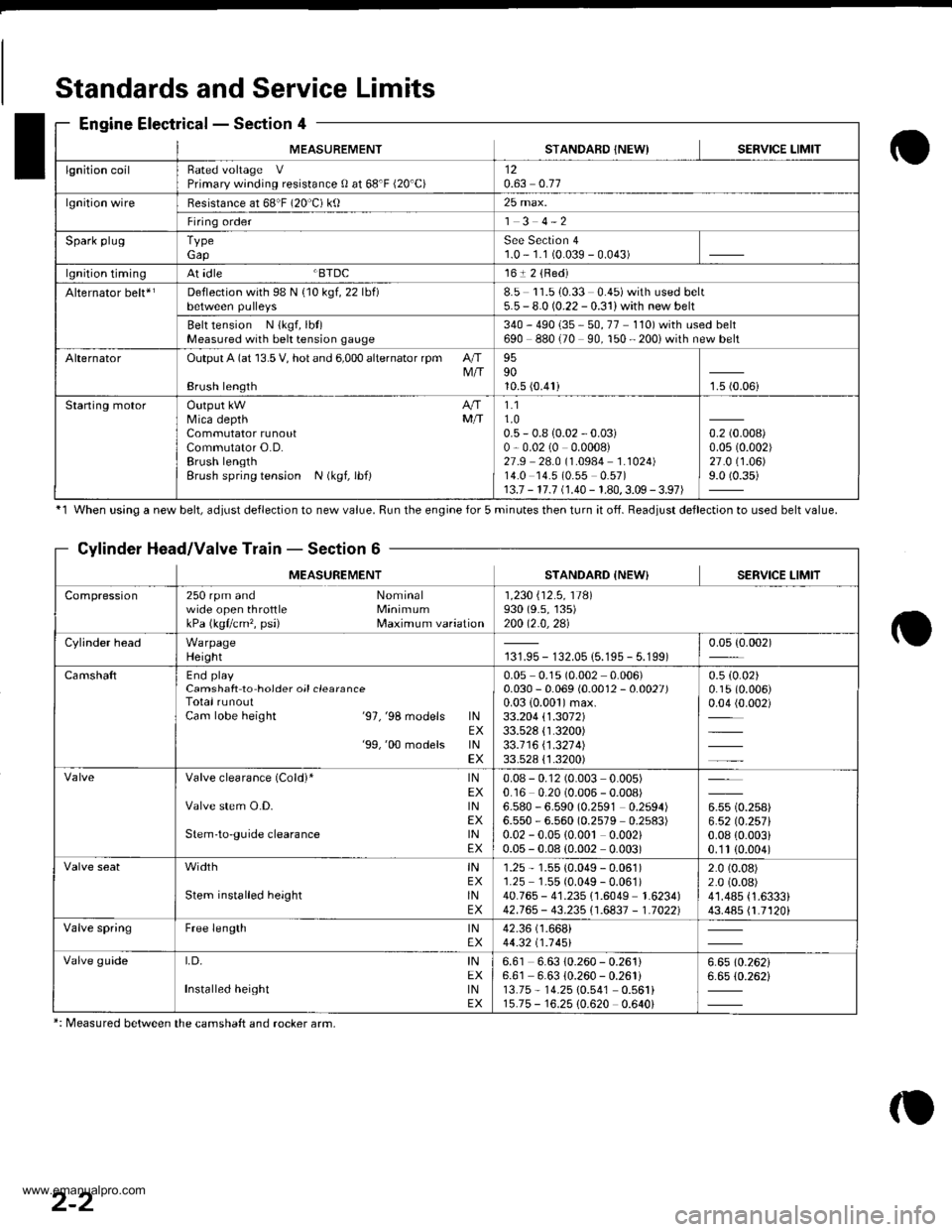
Standards and Service Limits
Engine Electrical - Section 4
'1 When using a new belt, ddiust deflection to new value. Run the engine for 5 minutes then turn it of{. Beadiust deflection to used belt value.
Cylinder Head/Valve Train - Section 6
MEASUREMENTSTANDARD {NEW} SERVICE LIMIT
Compression250 rpm and Nominalwide open throttle MinimumkPa (kgflcm', psi) Maximum variation
1 ,230 i'12 .5 , 11Al930 (9.s, 135)200 12.0,2al
Cylinder headWarpageHeight131.95 - 132.05 {5.195 - 5.199)0.05 {0.002)
CamshaftEnd playCamshaft to hoider oil clearanceTotal runoutCam lobe height '97,'98 models lNEX'99,'00 models lNEX
0.05 0.1s (0.002 0.006)0.030 - 0.069 (0.0012 - 0.0027)0.03 {0.001)max.33.204 \1.3072133.528 {1.3200)33.1 16 \1 .321 4)33.528 {'1.3200)
0.5 (0.02)
0.15 (0.006)
0.04 (0.002)
Valve clearance (Cold)* lNEXValve stem O.D. lNEXStem'to-guide clearance lNEX
0.08 - 0.12 (0.003 0.005)0.16 0.20 (0.006 - 0.008)6.580 - 6.590 (0.2591 0.2594)6.550 - 6.560 (0.2579 0.2s83)0.02 - 0.05 {0.00t 0.002)0.05 - 0.08 (0.002 0.003)
u* to.rutt6.52lO.257l0.08 {0.003i0.'1t (0.004)
width tNEXStem installed height lNEX
1.25 - 1.55 (0.049 - 0.061)1.25 1.55 (0.049 - 0.061)40.765 - 41.235 {1.6049 1.6234)42.765 - 43.235i'1.6837 - 1.70221
2.0 (0.08)
2.0 (0.08)
41.485 {1.6333}43.485 {1.7120i
Valve springFree length lNEX42.36 (1.668i
44.32 t1 .1 451
Valve guideI,D, INEXInstalled height tNEX
6.61 6.63 10.260 - 0.261)6.61 6.63 {0.260 - 0.261i13.75 - 14.25 10.541 0.561i15.75 - 16.25 {0.620 0.640i
6.6510.26216.65 (0.262i
*: Measured between the camshaft and rocker arm,
2-2
www.emanualpro.com
Page 28 of 1395
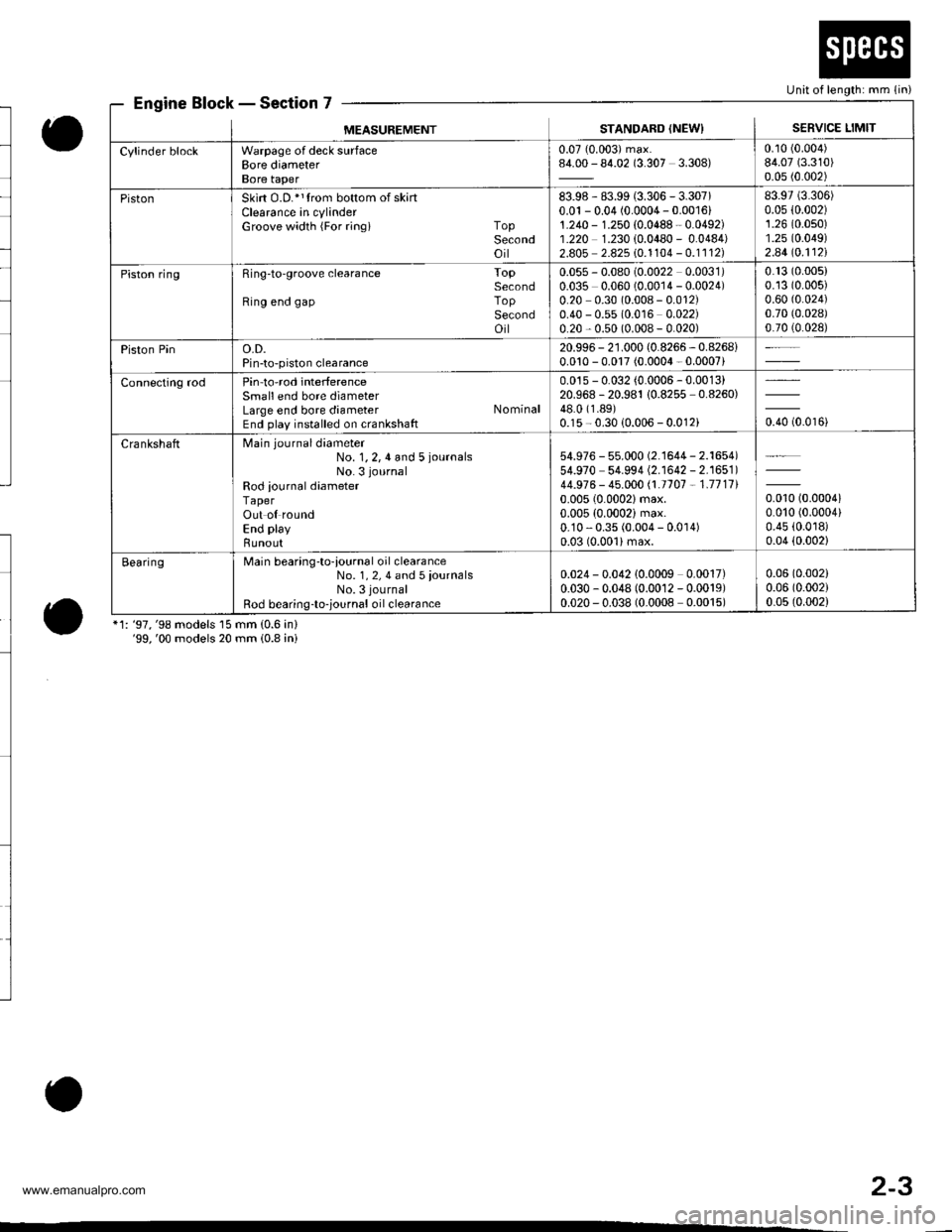
Engine Block - Section 7
o
o*1: '97,'98 models 15 mm (0.6 in)'99,'00 models 20 mm (0.8 ini
Unit of length: mm (in)
MEASUREMENTSTANDARD (NEWISERVICE LIMIT
Cylinder blockWarpage of deck surfaceBore diameterBore taper
0.07 (0.003) max.84.00 - 84.02 (3.307 3.308)0.10 (0.004)
84.07 (3.310)
0.05 (0.002)
PistonSkirt O.D.*1trom bottom of skartClearance in cylinderGroove width {For ringi TopSecondoil
83.98 - 83.99 (3.306 - 3.307)0.01 - 0.04 (0.0004 - 0.001611.240 - 1.250 {0.0488 - 0.0492)1.220 1.230 {0.0480 - 0.0484)2.805 2.825 10.1104 - 0.1112)
83.97 (3.306)
0.05 {0.002)1.26 (0.0s0)
1.25 (0.049)
2.44lo.112l
Piston ringRing-to'groove clearance ToPSecondRing end gap ToPSecondoil
0.055 - 0.080 (0.0022 0.0031)0.035 0.060 (0.0014 - 0.0024)0.20 0.30 (0.008 - 0.012)0.40 - 0.55 (0.016 0.022)0.20 - 0.50 (0.008 - 0.020)
0.13 (0.005)
0.13 (0.005)
0.60 (0.024)
0.70 (0.028)
0.70 (0.028)
Piston Pino.D.Pin-to-piston clearance
20.996 - 21.000 (0.8266 - 0.8268i0.010 - 0.017 (0.0004 - 0.0007)
Connecting rodPin-to-rod interferenceSmall end bore diameterLarge end bore diameter NominalEnd play installed on crankshaft
0.015 - 0.032 (0.0006 - 0.0013)20.968 -20.981 10.8255 -0.8260)
48.0 (1.89)
0.15 - 0.30 {0.006 - 0.012ioro to.oroi
CrankshaftMain journaldiameter
No. 1,2,4 and 5 iournalsNo. 3 journal
Rod iournal diameterTaperOut ol roundEnd play
Bunout
54.976 - 55.000 (2.'l644 - 2.1654)54.970 54.994 (2.1642 - 2.1651)44.976 - 45.000 /.1.1707 - 1.711110.005 (0.0002)max.
0.005 (0.0002) max.0.10 - 0.35 (0.004 - 0.0 r 4)0.03 (0.001)max.
0.010 (0.00041
0.010 (0.0004)
0.45 (0.0r8)
0.04 (0.002)
BearingMain bearing-to-iournal oil clearanceNo. 1, 2, 4 and 5 iournalsNo. 3 journal
Rod bearing-to-,ournal oil clearance
0.024 - 0.042 10.0009 0.0017)0.030 - 0.048 (0.0012 - 0.0019)0.020 - 0.038 (0.0008 0.0015)
0.06 (0.002)
0.06 (0.002)
0.05 (0.002)
o
2-3
www.emanualpro.com
Page 41 of 1395
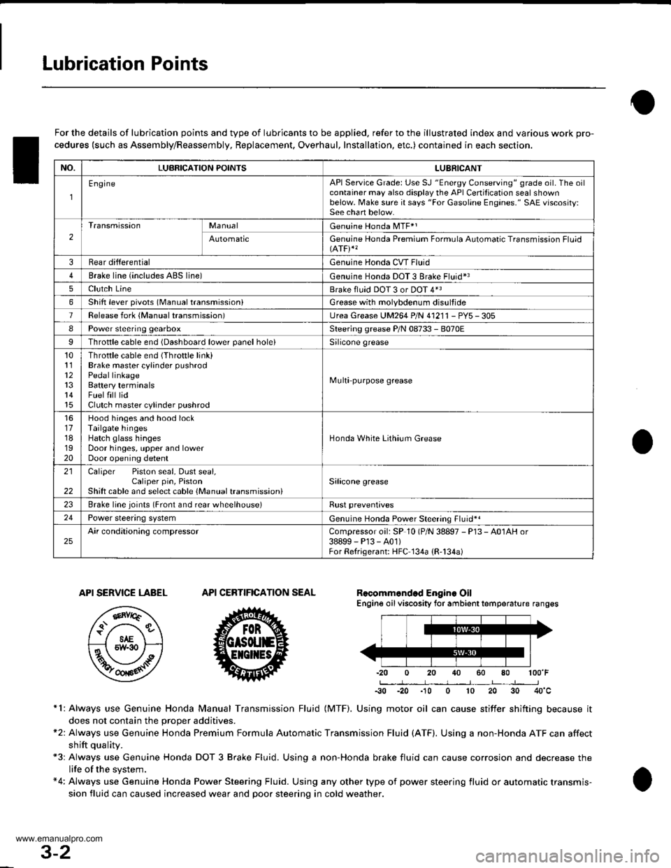
Lubrication Points
For the details of lubrication points and type of lubricants to be applied. refer to the illustrated index and various work pro-
cedures (such as Assembly/Reassembly, Replacement, Overhaul, Installation, etc.) contained in each section.
Recomm6nded Engine OilEngine oil viscosity for ambient temperature ranges
100'F
-30 -20 .10 0 10 20 30 40'c
r1: Always use Genuine Honda Manual Transmission Fluid {MTF). Using motor oil can cause stiffer shifting because it
does not contain the orooer additives.*2: Always use Genuine Honda Premium Formula Automatic Transmission Fluid (ATF). Using a non-Honda ATF can affect
shift qualitv.+3r Always use Genuine Honda DOT 3 Brake Fluid. Using a non-Honda brake fluid can cause corrosion and decrease the
life of the system.*4: Always use Genuine Honda Power Steering Fluid. Using any other type of power steering fluid or automatic transmis-
sion fluid can caused increased wear and poor steering in cold weather.
API SERVICE LABEL
/,.*-G\
/.'z-\e\t/6AE\ll-;-1 5w-30 /---l
w
API CERTIFICATION SEAL
ffi-20 0 20
NO.LUBRICATION POINTSLUBRICANT
EngineAPI Service Grade: Use SJ "Energy Conserving" grade oil. The oilcontainer may also display the API Certitication seal shownbelow. Make sure it says "For Gasoline Engines." SAE vjscosity:See chart below.
2
TransmissionManualGenuine Honda MTF*1
AutomaticGenuine Honda Premium Formula Automatic Transmission Fluid(ATF)*'
3Rear differentialGenuine Honda CVT Fluid
4Brake line (includes ABS line)Genuine Honda DOT 3 Brake Fluid*3
5Clutch LineBrake fluid DOT 3 or DOT 4*3
6Shift lever pivots (Manual transmission)Grease with molybdenum disultide
1Release fork (Manual transmission)LJrea Grease UM264 P/N 4'1211 - PYs - 305
IPower steering gearboxSteering grease P/N 08733 - B070E
Throttle cable end {Dashboard lower panel holelSilicone grease
10l112
14
Throttle cable end (Throttle link)Brake master cylinder pushrodPedal linkageBattery terminalsFuelfill lidClutch master cylinder pushrod
Multi purpose grease
1617181920
Hood hinges and hood lockTailgate hingesHatch glass hingesDoor hinges, upper and lowerDoor opening detent
Honda White Lithium Grease
21
22
Caliper Piston seal, Dust seal,Caliper pin, PistonShilt cable and select cable {Manual transmission)Silicone grease
23Brake line ioints (Front and rear wheelhouse)Rust preventives
24Power steering systemGenuine Honda Power Steering Fluid-.
25Air conditioning compressorCompressor oil: SP 10 lP/N 38897 - P13 - A0lAH or38899-P13-A01)For Refrigerant: HFC 134a (R,134a)
3-2
www.emanualpro.com
Page 57 of 1395
RE
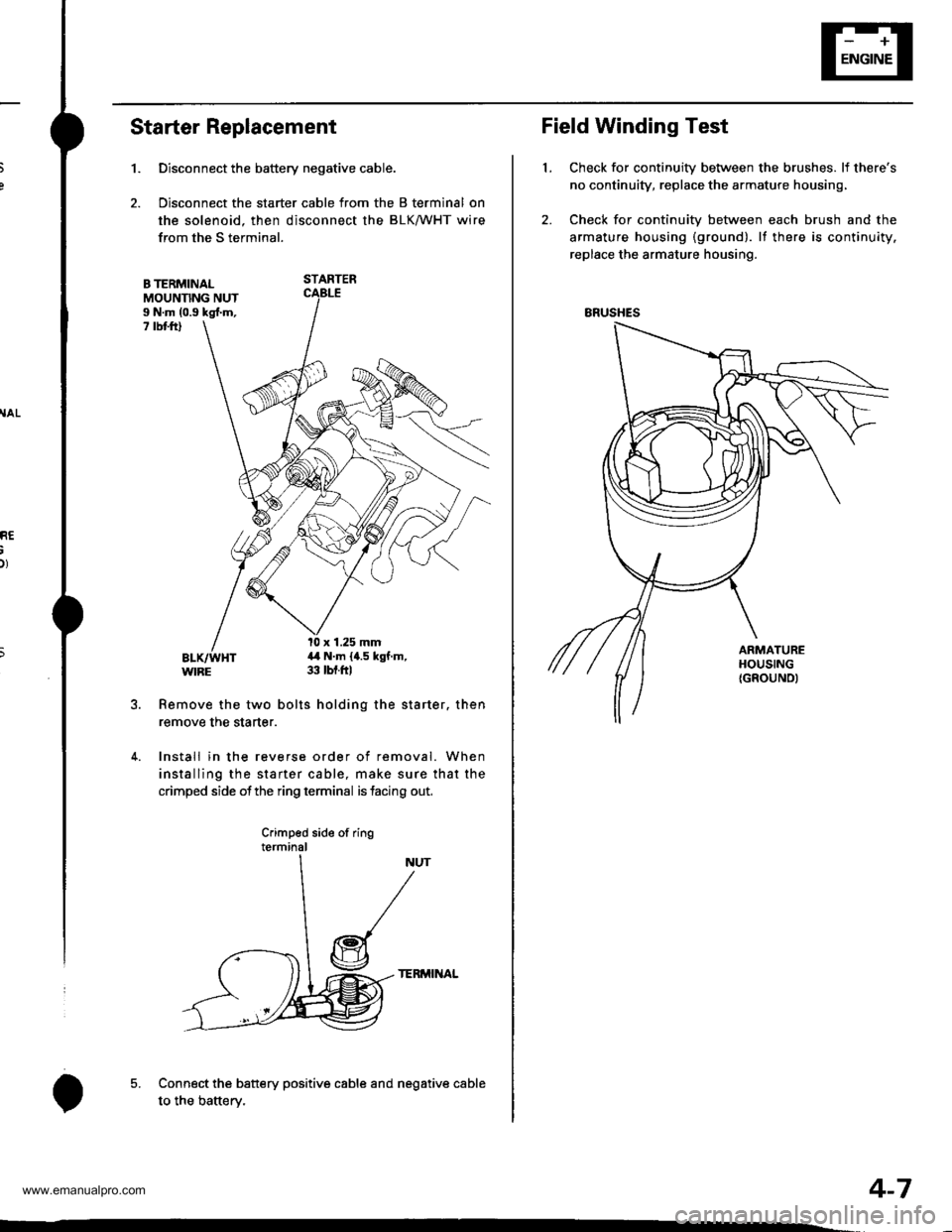
Starter Replacement
1.
B TERMINALMOUNNNG NUTI N.m (0.9 kgl.m,7 rbt ftl
Remove the two bolts holding the starter. then
remove the starter.
4. Install in the reverse order of removal. When
installing the starter cable, make sure that the
crimped side ofthe ring terminal is facing out,
Crimped side of ringterminal
TERMINAL
Connect the battery positive cable and negative cable
to the batterv.
Disconnect the battery negative cable.
Disconnect the starter cable from the B terminal on
the solenoid. then disconnect the BLK/WHT wire
from the S terminal.
STARTER
l0 x 1.25 mm4,1 N.m {4.5 kgf.m,33 tbt.ftl
5.
o
Field Winding Test
Check for continuity between the brushes. lf there's
no continuity, replace the armature housing,
Check for continuity between each brush and the
armature housing {ground). lf there is continuity.
replace the armature housing.
t.
ERUSHES
4-7
www.emanualpro.com
Page 59 of 1395
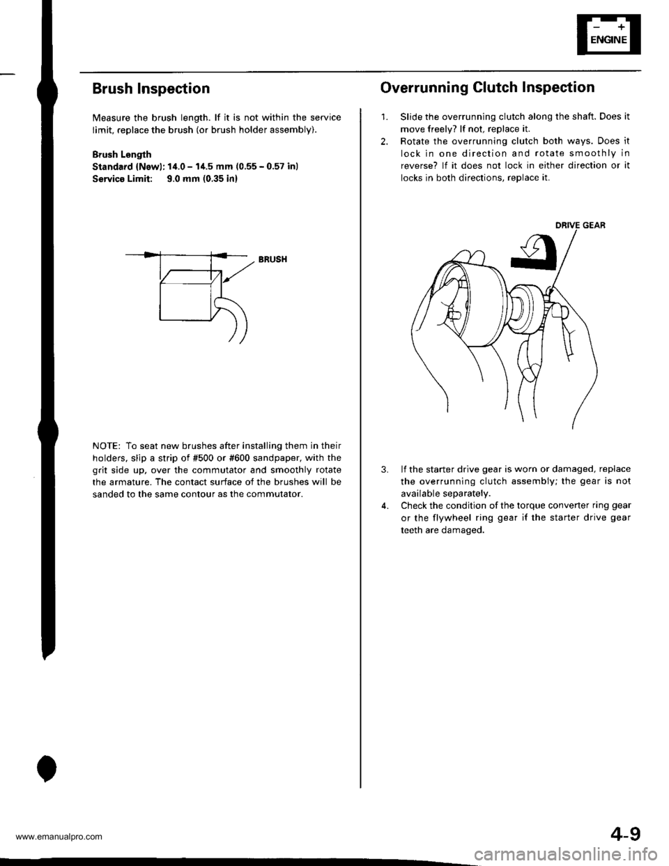
Brush Inspection
Measure the brush length. lf it is not within the service
limit, replace the brush (or brush holder assembly).
Brush Lsngth
Standard {Newl: 14.0 - I'1.5 mm (0.55 - 0.57 inl
Servico Limit: 9.0 mm (0.35 in)
NOTE: To seat new brushes after installing them in their
holders. slip a strip of #500 or #600 sandpaper, with the
grit side up, over the commutator and smoothly rotate
the armature. The contact surface of the brushes will be
sanded to the same contour as the commutator.
BRUSH
4-9
2.
1.
Overrunning Clutch Inspection
Slide the overrunning clutch along the shaft. Does it
move freely? lf not, replace it.
Rotate the overrunning clutch both ways. Does it
lock in one direction and rotate smoothly in
reverse? lf it does not lock in either direction or it
locks in both directions, reDlace it.
3.lf the starter drive gear is worn or damaged, replace
the overrunning clutch assembly; the gear is not
available separately.
Check the condition of the torque converter ring gear
or the flywheel ring gear if the starter drive gear
teeth are damaged.
www.emanualpro.com
Page 62 of 1395
Starting System
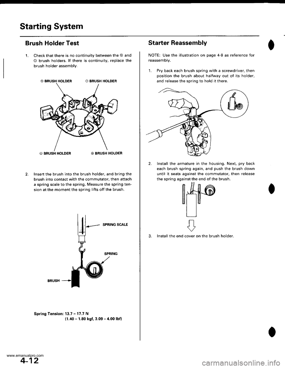
Brush Holder Test
1. Check that there is no continuity between the O and
O brush holders. lf there is continuitv, replace the
brush holder assembly.
O BRUSH HOLDER@ BRUSH HOLDER
Insert the brush into the brush holder, and bring the
brush into contact with the commutator, then attach
a spring scale to the spring. Measure the spring ten-
sion at the moment the spring lifts off the brush.
SPRING SCALE
Spring Tension: 13.7 - 17.7 N
(1.40 - 1.80 kgf, 3.09 - 4.00 lbf)
4-12
Starter Reassembly
NOTE: Use the illustration on page 4I as reference for
reassemDty.
1. Pry back each brush spring with a screwdriver, then
position the brush about halfway out ol its holder,
and release the spring to hold it there.
2. Install the armature in the housing. Next, pry back
each brush spring again, and push the brush down
until it seats against the commutator, then release
the spring against the end of the brush.
- E^
F*4#-@
6t taal la
tlll
3. Install the endon the brush holder.
ft
cover
www.emanualpro.com