Page 125 of 1395
Timing Belt
Installation (cont'd)
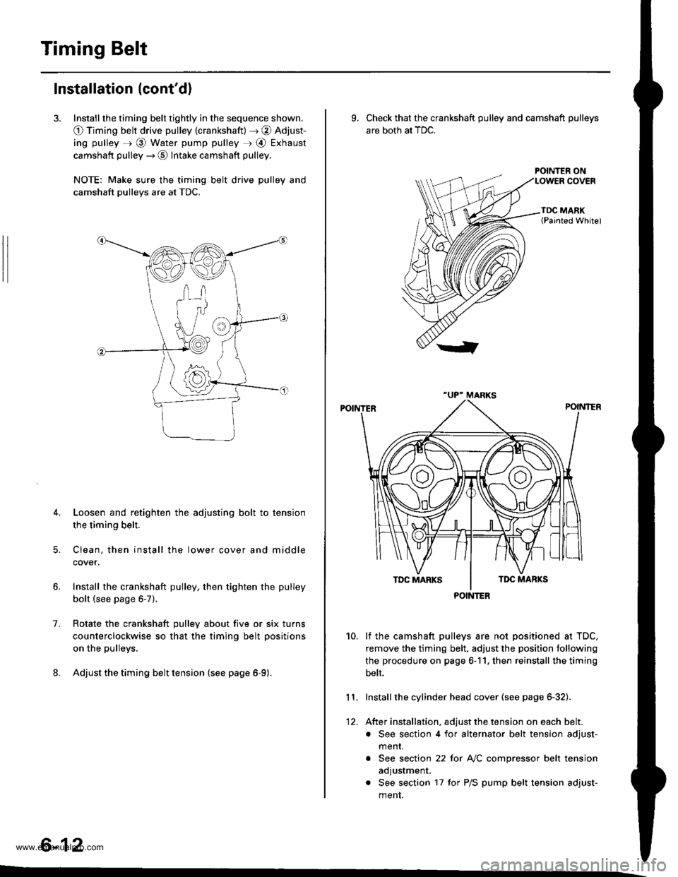
3. Install the timing belt tightly in the sequence shown.
O Timing belt drive pulley (crankshaft) J @ Adjust-
ing pulley =r @ Water pump pulley r @ Exhaust
camshaft pulley --) @ Intake camshaft pulley.
NOTE: Make sure the timing belt drive pulley and
camshaft pulleys are at TDC.
4. Loosen and retighten the adjusting bolt to tension
the timing belt.
5. Clean. then install the lower cover and middle
cover.
Install the crankshaft pulley, then tighten the pulley
bolt (see page 6-7).
Rotate the crankshaft pulley about five or six turns
counterclockwise so that the timing belt positions
on the pulleys.
Adjust the timing belt tension {see page 6-9).
1.
6-12
9. Check that the crankshaft pulley and camshaft pulleys
are both at TDC.
POINTER ON
lf the camshaft pulleys are not positioned at TDC,
remove the timing belt. adjust the position following
the procedure on page 6-11. then reinstall the timing
belt.
Installthe cylinder head cover (see page 6-32).
After installation, adjust the tension on each belt.
. See section 4 for alternator belt tension adjust-
menr.
. See section 22 for NC compressor belt tension
adjustment.
. See section 17 for P/S pump belt tension adjust-
ment.
10.
11.
12.
POINTER
www.emanualpro.com
Page 126 of 1395
CKF Sensor
Replacement
1.
|o|'ln PUUCY BMCKET SOLIl0 r 1.25 mm14 .m 14.5 kgl.m,3:' lbtftl
Remove the guard bar and splash shield (see page
5-7 t.
Loosen the lock bolt and mounting bolt, then
remove the P/S pump belt.
MOUNTING BOLT8 x 1.25 mm
PUMPBELT
Loosen the adjusting bolt and idler pulley bracket
bolt, then remove the Ay'C comDressor belt.
ADJUSTING BOLTLOCKNUT8 x 1.25 mm24 N.m {2.4 kgf.m, 17 lbf.ft)
24 N.m (2.{ kgf.m, 17 lbf.ttl
24 N.m 12.4 lgf.m, 17 lbl.ftl
4. Loosen the locknut and mounting nut, then remove
the alternator belt.
LOCKNUT8 x 1.25 mm24 N.m (2.4 kgl.m, 17 lbtftl
10 x 1 .25 mma4 N.m (4.5 kgt m, 33 lbtft)
E
6.
7.
aJ.
Remove the cylinder head cover.
Remove the crankshaft pulley (see page 6-7).
Remove the middle cover and the lower cover.
Disconnect the CKF sensor connector, then remove
the CKF sensor.
6x1.0mm11 N.m {1.r kgnm,8.0 lbfft)
9. Install the CKF sensor in reverse order of removal.
BELT
CKF SENSOR
6-13
www.emanualpro.com
Page 127 of 1395
Gylinder Head
lllustrated Index
To avoid damage, wait until the engine coolant temperature drops below 100'F (38'C) before removing the cylinder head.
6x1.0mm9.8 N.m (1.0 kgI.m, 7.2 lbf.ft)WASHERReplace when damagedor deteriorated,CYLINDER HEADCOVEBReter to page 6 32 wheninstalling cylinder head cover.
HEAO COVER GASKETBeplace when leaking,damaged or deteriorated.Apply liquid gasket atthe eight corners of the
RUBEER SEALReplace ifor deteriorated,
8 x 1.25 mm24 N.m (2.4
17 tbtft)
See section 4.
CYLINDEBHEAD PLUGReplace-
---..-@0+---.."...-
s<-- KEY
6x1.0mm9.8 N.m (1.0 kgf.m.7.2 tbf.foApply engine oil to thethreads.
CAMSHAFTHOLDER
DOWELPIN
OIL SEALReplace.
CAMSHAFTPULLEY
8 x 1.25 mm37 N.m {3.8 kgf.m,27 tbtft)
OIL SEALReplace.
6x1.0mm9.8 N.m (1.0 kgl.m, 7.2lbtftl
6-14
www.emanualpro.com
Page 128 of 1395
-?E
handling a metal gasket. take care not to fold it or damage the contact surface.
Prior to reassembling, clean all the parts in solvent, dry them and apply lubricant to any contact parts.
CYLINDER HEAD BOLT11 x 1.5 mm85 N.m {8.7 kgf.m,6:} lbf.ft)Tightening, page 6'30.Apply engine oilto the threads.VALVEKEEPERS
\
END PIVOT BOLT63 N.m 16.4 kgl m, 46 lbf.ft)
EXHAUSY VALVESEALReplace.
EXHAUST VALVEGUIDEInspection, page 6-25Replacem6nt, page 6-25Reaming, page 6-27
10 x 1.25 mm4,0 N.m {i1.5 kgf.m.33 rbf.ft)
GASKETReplace.
OIL CONTROLORIFICEClean.
EXHAUST VALVESPRING
SPRING BETAINER
INTAKE VALVESPRING
INTAKE VALVE SEALReplace.
VALVE SPRINGSEAT
INTAKE VALVEGUIDE
Removal, page 6-16Warpage, page 6 27Valve seat reconditioning,page 6 28Installation, page 6-30
EXHAUSTVALVE
INTAKE VALVERemoval, page 6-23Installation, page 6-29
CYLINDER HEAO
HEAD
O.RINGReplace.
8 x 1.25 mm24 N.m (2.4 kgf.m,17 tbf.ft)
DOWEL PIN
6-15
www.emanualpro.com
Page 135 of 1395
Camshafts
4.
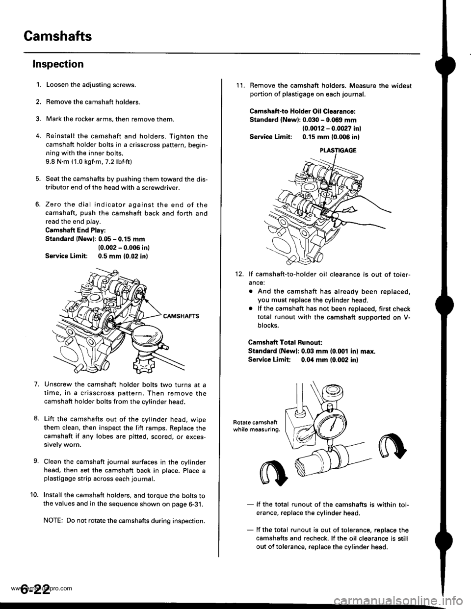
Inspection
1.
7.
Loosen the adjusting screws.
Remove the camshaft holders.
Mark the rocker arms, then remove them.
Reinstall the camshaft and holders. Tighten the
camshaft holder bolts in a crisscross pattern, begin-
ning with the inner bolts.
9.8 N.m (1.0 kgf.m.7.2 lbf.ft)
Seat the camshafts by pushing them toward the dis-
tributor end of the head with a screwdriver.
Zero the dial indicator against the end of the
camshaft, push the camshaft back and forth and
read the end play.
Camshaft End Play:
Standard lNewl: 0.05 - 0.15 mm
10.002 - 0.005 in)
Service Limit: 0.5 mm (0.02 in)
Unscrew the camshaft holder bolts two turns at a
time, in a crisscross pattern, Then remove the
camshaft holder bolts from the cvlinder head.
Lift the camshafts out of the cylinder head. wipe
them clean, then inspect the lift ramps, Replace the
camshaft if any lobes are pitted, scored, or exces-
sively worn.
Clean the camshaft journal surfaces in the cylinder
head, then set the camshaft back in Dlace. Place aplastigage strip across each journal.
Install the camshaft holders. and torque the bolts tothe values and in the sequence shown on page 6-31.
NOTE: Do not rotate the camshafts during inspection.
8.
10.
6-22
11. Remove the camshaft holders. Measure the widest
portion of plastigage on each journal.
Camshatt-to HoldGr Oil Clearance:
Standard {Newl: 0.030 - 0.069 mm
{0.0012 - 0.0027 in}
Servico Limit: 0.15 mm (0.006 in)
12. lf camshaft-to-holder oil clearance is out of toler-
ance:
. And the camshaft has already been replaced,
you must replace the cylinder head.. lf the camshaft has not been replaced, first check
total runout with the camshaft suoDorted on V-
blocks.
Camshaft Total Runout:
Standard (N6w): 0.03 mm (0.001 in) max.
Service Limit 0.04 mm (0.(X)2 in)
Rotat6 camshattwhile measuring.
- lf the total runout of the camshafts is within tol-
erance, replace the cylinder head
- lf the total runout is out of tolerance, replace the
camshafts and recheck. lf the oil clearance is still
out of tolerance, replace the cylinder head.
www.emanualpro.com
Page 136 of 1395
Valves, Valve Springs
and Valve Seals
13. Measure the cam lobe height.
Cam Lobe Height Standard (Newl'97 - 98 models:
INTAKE: 33.20,1mm (1.3072 in)
EXHAUST: 33.528 mm (1.3200 inl'99 - 00 models:
INTAKE: 33.716 mm 11.327t1in)
EXHAUST:33.528 mm (1.3200 in)
Inspect this area lor wear.
Removal
ldentify the valves and valve springs as they are
removed so that each item can be reinstalled in its origi-
nal Dosition.
1. Using an appropriate-sized socket and plastic mallet.
lightly tap the valve retainer to loosen the valve keeP
ers before installing the valve spring compressor'
2. Install the spring compressor. Compress the spring
and remove the valve keeper.
VALVE SPRING COMPRESSORKD No. 3&!. whh *'5 JAW o.
VALVE SPRING COMPRESSORATTACHMEUT07757 - PJ1010A
(cont'd)
6-23
www.emanualpro.com
Page 137 of 1395
Valves, Valve Springs and Valve Seals
Removal (cont'dl
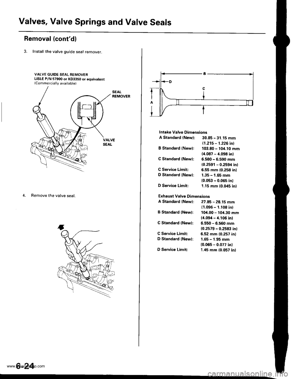
3. Install the valve guide seal remover.
VALVE GUIDE SEAL REMOVERLISLE P/N 57900 or KD3350 or equivalent(Commerciallv available)
4. Remove the valve seal.
6-24
Intake Valve Dimensions
A Standard {New}: 30.85 - 31.15 mm
B Standard (New):
G Standard {Newl:
C Service Limiti
D Standard lNewl:
D Service Limit:
B Standard (Newl:
C Standard {New):
C Service Limit:
D Standard lNewl:
D Service Limit:
11.21s - 1.226 inl
103.80 - 10/t.10 mm
{i[.087 - 4.098 in)
6.580 - 6.590 mm(0.2591 - 0.2594 in)
6.55 mm (0.258 inl
1.35 - 1.65 mm(0.053 - 0.05s in)
1.15 mm (0.045 in)
11.096 - 1.108 in)
10,1.00 - 10,1.30 mm(il.09i[ - it.l06 in)
6.550 - 6.560 mm
10.2579 - 0.2583 inl
6.52 mm (0.257 inl
1.65 - 1.95 mm
10.065 - 0.077 in)
1.45 mm (0.057 inl
Exhausi Valv€ Dimensions
A Standard (Newl: 27.85 - 28.15 mm
www.emanualpro.com
Page 139 of 1395
Valve Guides
Replacement (cont'dl
5.
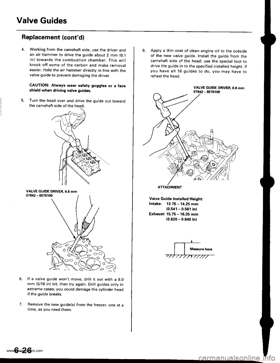
Working from the camshaft side, use the driver andan air hammer to drive the guide about 2 mm (O.l
in) towards the combustion chamber. This willknock off some of the carbon and make removaleasier. Hold the air hammer directly in line with thevalve guide to prevent damaging the driver.
CAUTION: Always wear satety goggles or a faceshield when driving valve guidss.
Turn the head over and drive the guide out towardthe camshaft side of the head.
li a valve guide won't move, drill it out with a 8.0mm (5/16 in) bit, then try again. Dritt guides onty inextreme cases; you could damage the cylinder headif the guide breaks.
Remove the new guide(s) from the freezer, one at atlme, as you need them.
6.
7.
6-26
'o C'
8. Apply a thin coat of clean engine oil to the outsideof the new valve guide. Install the guide from thecamshaft side of the head; use the special tool todrive the guide in to the specified installed height. lfyou have all 16 guides to do, you mav have toreheat the head.
Valve Guide Installed Height:
Intake: 13.75 - 1i1.25 mm
{0.5,[1 - 0.561 in)
Exhaust: 15.75 - 16.25 mm(0.620 - 0.640 inl
ATTACHMENT
www.emanualpro.com