Page 19 of 1395

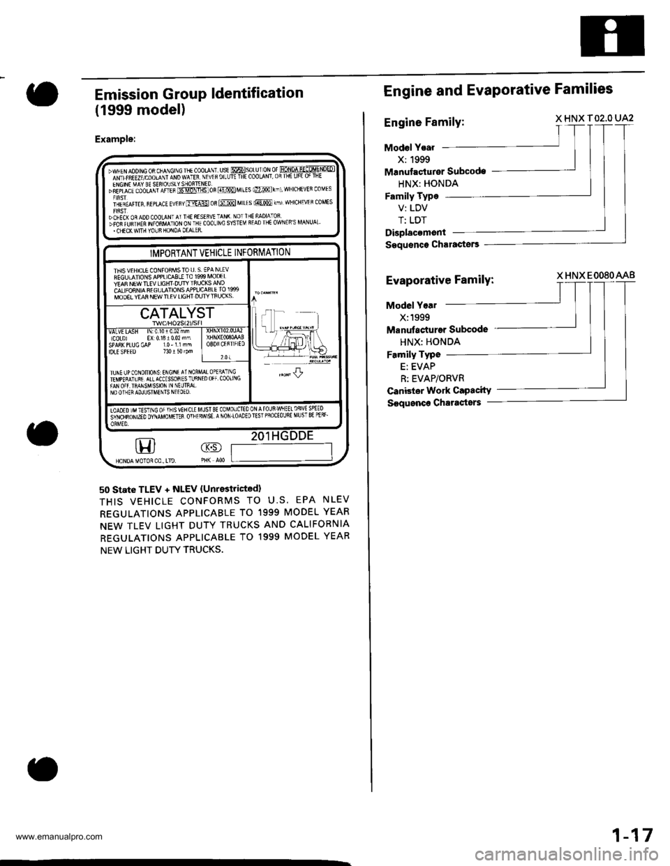
Emission Group ldentification
(1999 model)
Example:
50 state TLEV + NLEV {Unrestricted}
THIS VEHICLE CONFORMS TO U.S. EPA NLEV
REGULATIONS APPLICABLE TO 1999 MODEL YEAR
NEW TLEV LIGHT DUTY TRUCKS ANO CALIFORNIA
REGULATIONS APPLICABLE TO 1999 MODEL YEAR
NEW LIGHT DUTY TRUCKS.
'.WNEN AOO NG OR CNANGINC THE COOLANT. USE @SOLU I ON Of FONOA U-ECo-q.�NOEDImcrtniuvcoourr mo wlttt NEVEF oILLJTE THE CooLANT,0RTHE LIFE 0F TNE
"Eifil:$o""niii?i,THffi ffi'"R @ M LEs lmo rhl, wNrcHEVEn coMEs
i'lrt^t orrrr, ^,r*a, rurr"* os @ M LEs 1@ kmr wNICHEVER coMEs
}CNECK OR ADD COOLANT AT THE RESER!'E TAN( NOT IHE NADIATOSDFOfi fWTHEF NFORMATION ON THE COOL NC SYSTEM READ THE OWNER'S MANUAL'' CHECK WIIH YOUS HONOA OEALER.
GD
IMPORTANT VEHICLE INFORMATION
THIS VEHICLE CONFOAMSTOU. S EPA NLEVFEGULANONS APPLICCBLI TO 1999 MOD€LYEA8 NEW TIEV LIGHT DUTY ]nUCKS ANDCALIFORNIA REGULATIONS APPLICASLE IO 19S9MOOEL YEAR NEW TLEV LIGHT DUTY IFIJCKS,,|F --'-
Ll: .-.-,1
I rFrll\=#_H*
CATALYST
VALVE IASN lN:010r0.02 mmlCoLDj EX 0131002 mmSPA8K PLUG GAP 10- l l nmIDLE SPEED 130 t 5{ rPmOBDIICERT]ATD
201
TUNE I]PCONDIIIONS INGINEAT NOBTEI\'PERATUR€ ATL ACCESSOS ES TLJRNFAN OFf IRANSMSSION N NEL]TMLNO OINER ADJUSTMTNTS NEEOEO.
JL
Iooro nr tist rc orn svtncrE MUsT BE coMoufitooNArounwNEElDslvE SPEEDiitriunor mo ovuvo uenn orr Enw sE a NoN.loaDE D rEsr PRoCE ouRE MU sT 8E Pf Rr-
Engine and Evaporative Families
Engine Family:X HNX T02,O UA2
Model Year
X:1999
Manutao{urer Subcode
HNX: HONDA
Family Type
V: LDV
T: LDT
Displacoment
Saquence Charactors
Evaporative Family:X HNX EOO8OAAB
Model Yoal
X:1999
Manutacturar Subcode
HNX: HONDA
Family Typo
E: EVAP
R: EVAP/ORVR
Canbter Work Capacity
S€quonce Chartsters
1-17
www.emanualpro.com
Page 27 of 1395

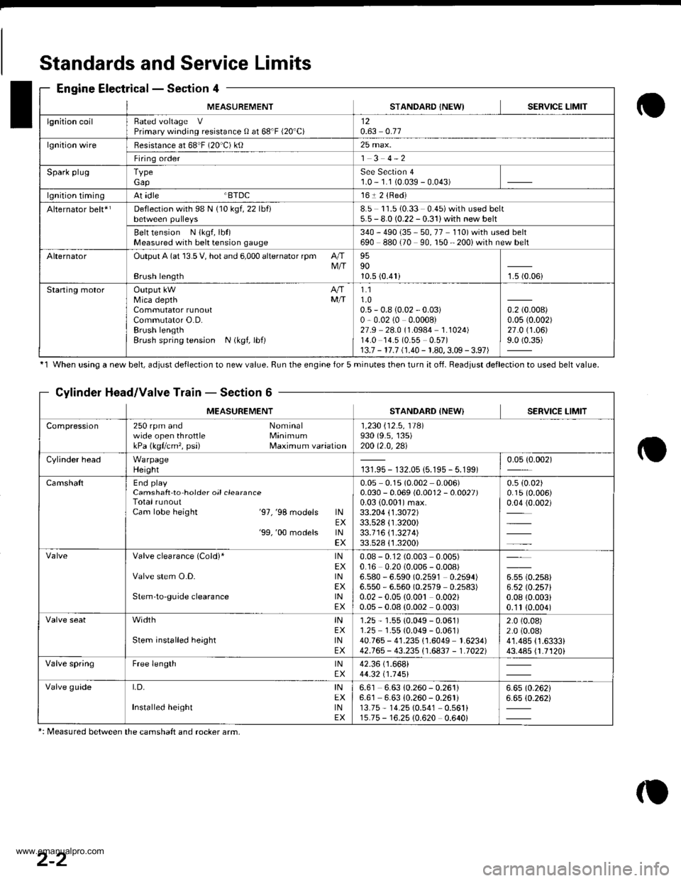
MEASUREMENTSTANDAFD INEWISERVICE LIMIT
lgnition coilRated voltage VPrimary winding resistance 0 at 68'F (20'C)120.63 0.77
lgnition wireBesistance at 68"F (20 C) ktl25 max.
Firing order1 3 4-2
Spark plugTypeGapSee Section 41.0 - 1.1 (0.039 - 0.043)
lgnition timingAt idle BTDC161 2 {Red)
Alternator belt*rDeflection with 98 N {10 kgf, 22 lbf)8.5 11.510.33 0.45)with used belt5.5 - 8.0 (0.22 - 0.31) with new belt
Belt tension N {kgf, lbt)Measured with bek tension gauge340 - 490 {35 - 50, 77 110) with used belt690 880 (70 90, 150 - 200i with new belt
AlternatorOutput A (at 13.5 V, hot and 6,000 alternator rpm AIIM/IBrush length
959010.5 (0.41)1.5 (0.06i
Staning motorOutput kW A/fMica depth MfiCommutator runoutCommutator O.D.Brush lengthBrush spring tension N (kgf, lbf)
1.11.00.5 - 0.8 {0.02 - 0.03)0,0.02 (0 0.0008)27.9 28.0 (1.0984 1.1024)14.0 14.5 (0.55 0.57)13.7 - 17.7 (1.40 - 1.80,3.09 - 3.97)
0.2 (0.008)
0.0s (0.002)
27.0 (1.06)
9.0 (0.35)
Standards and Service Limits
Engine Electrical - Section 4
'1 When using a new belt, ddiust deflection to new value. Run the engine for 5 minutes then turn it of{. Beadiust deflection to used belt value.
Cylinder Head/Valve Train - Section 6
MEASUREMENTSTANDARD {NEW} SERVICE LIMIT
Compression250 rpm and Nominalwide open throttle MinimumkPa (kgflcm'�, psi) Maximum variation
1 ,230 i'12 .5 , 11Al930 (9.s, 135)200 12.0,2al
Cylinder headWarpageHeight131.95 - 132.05 {5.195 - 5.199)0.05 {0.002)
CamshaftEnd playCamshaft to hoider oil clearanceTotal runoutCam lobe height '97,'98 models lNEX'99,'00 models lNEX
0.05 0.1s (0.002 0.006)0.030 - 0.069 (0.0012 - 0.0027)0.03 {0.001)max.33.204 \1.3072133.528 {1.3200)33.1 16 \1 .321 4)33.528 {'1.3200)
0.5 (0.02)
0.15 (0.006)
0.04 (0.002)
Valve clearance (Cold)* lNEXValve stem O.D. lNEXStem'to-guide clearance lNEX
0.08 - 0.12 (0.003 0.005)0.16 0.20 (0.006 - 0.008)6.580 - 6.590 (0.2591 0.2594)6.550 - 6.560 (0.2579 0.2s83)0.02 - 0.05 {0.00t 0.002)0.05 - 0.08 (0.002 0.003)
u* to.rutt6.52lO.257l0.08 {0.003i0.'1t (0.004)
width tNEXStem installed height lNEX
1.25 - 1.55 (0.049 - 0.061)1.25 1.55 (0.049 - 0.061)40.765 - 41.235 {1.6049 1.6234)42.765 - 43.235i'1.6837 - 1.70221
2.0 (0.08)
2.0 (0.08)
41.485 {1.6333}43.485 {1.7120i
Valve springFree length lNEX42.36 (1.668i
44.32 t1 .1 451
Valve guideI,D, INEXInstalled height tNEX
6.61 6.63 10.260 - 0.261)6.61 6.63 {0.260 - 0.261i13.75 - 14.25 10.541 0.561i15.75 - 16.25 {0.620 0.640i
6.6510.26216.65 (0.262i
*: Measured between the camshaft and rocker arm,
2-2
www.emanualpro.com
Page 29 of 1395

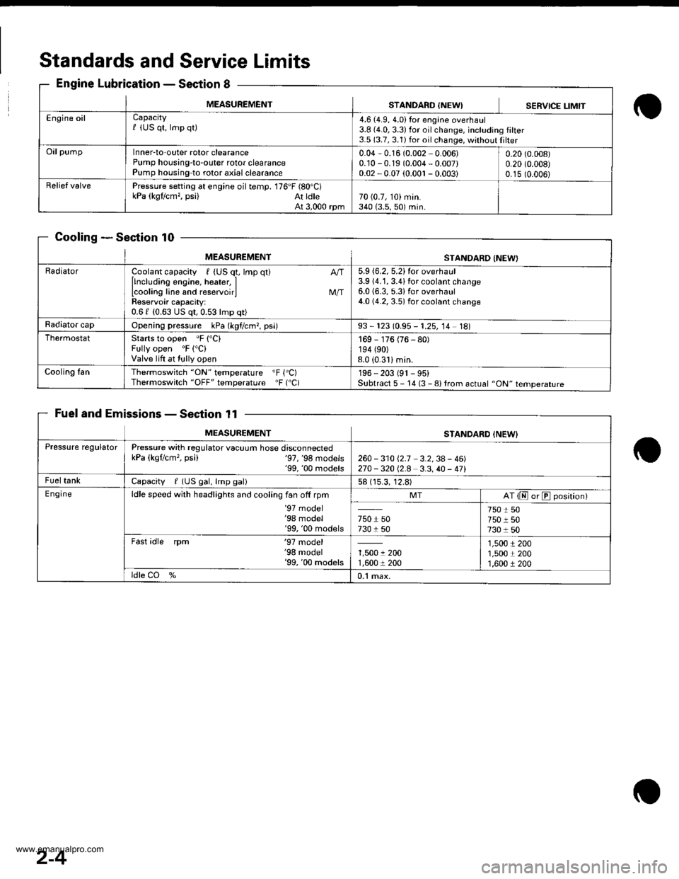
Standards andService Limits
Engine LubricationSection 8
CoolingSection 10
Fuel and EmissionsSection 11
MEASUREMENTSTANDARO {NEWISERVICE LIMIT
Engine oilCapacityf (US qt, lmp qt)4.6 (4.9, 4.0)Ior engine overhaul3.8 {4.0,3.3)for oilchange, including filter3.5 (3.7, 3.1) for oil change, without Iilter
OilpumpInner-to-outer rotor clearancePump housing-to-outer rotor clearancePump housing-to rotor axial clearance
0.04 - 0.16 (0.002 - 0.006)0.10 -0.19 (0.004 - 0.007)0.02 -0.07 (0.001 - 0.003i
0.20 (0.008)
0.20 (0.008)
0.15 (0.006)
Relief valvePressure setting at engine oil temp. 176'F (80'C)kPa (kgt/cm,, psi) At ldleAt 3,000 rpm70 (0.7, 10) min.340 {3.5,50) min.
MEASUREMENTSTANDARO INEW}
RadiatorCoolant capacity , (US q1, lmp qt)
llncluding engine, heater, ILcooling line and reservoirlReservoir capacity:0.61 (0.63 US qt,0.53lmp qt)
M/T
5.9 {6.2, 5.2}tor overhaul3.9 (4.1, 3.4ifor coolant change6.0 (6.3, 5.3ifor overhaul4.0 (4.2, 3.5) for coolant change
Radiator capOpening pressure kPa (kgf/cm?, psi)93 - 123 (0.95 - 1.25, 14 18)
ThermostatStarts to open 'F 1"C)Fully open 'F ("C)
Valve lift at tully open
169 - 176 (76 - 80)194 (90)
8.0 (0.31imin.
Cooling fanThermoswitch "ON" temperature "F {'C)Thermoswitch "OFF" temperature 'F ('C)196 - 203 (91 - 95)Subtract 5 - 14 (3 - 8) trom actual "ON" temperature
MEASUREMENTSTANDARD INEW}
Pressure regulatorPressure with regulator vacuum hose disconnectedkPa (kgflcm'�, psi) '97,'98 models'99, '00 rnodels260 - 31012.7 3.2,38- 46)270 -32012.8 3.3,40 - 471
FueltankCapacity / (US gal, lmp gal)58 (15.3, 12.8)
E ngineldle speed with headlights and cooling fan off rpm'97 model'98 model'99, '00 models
MTAT {E or E position)
750 r 50730 1 50
750 t 50750 r 507301 50
Fast idle rpm '97 model'98 model'99, '00 models1,5001 2001,600 r 200
1,5001 2001,5001 2001,600 r 200
ldle CO %0.1 max.
2-4
www.emanualpro.com
Page 191 of 1395
Engine Hose Connections:
FAST IDLE THERMOVALVE (A/T onlyl
IDLE AIR CONTROLIIAC}VALVE
TEF BYPASSHOSE
THERMOSTATHOUSING
CONNECTINGPIPE
VALVE
HOSES
10-3
www.emanualpro.com
Page 207 of 1395
Component Locations
Index (cont'dl
39 - 00 models:
MANIFOLD ABSOLUTEPRESSURE IMAPISENSORTroubleshooting, page 1 1-90
THROTTLE POSITION {TP)SENSORTroubleshooting, page 1 1-103
IDLE AIR CONTROL OACI VALVETroubleshooting, page 1 1-152
EVAPOBATIVE EMISSION {EVAPICONTROL CANISTER VENT SHUTVALVETroubleshooting, page 1 1-213
EVAPORATIVE EMISSION(EVAPI PURGE CONTROI-SOLENOID VALVETroubleshootang, page 1 1-2'13
ELECTRICAL LOAOOETECTOR {ELD) IUSA modet)Troubleshooting, page I 1-138
INTAKE AIR TEMPERATURE(IAT) SENSORTroubleshooting, page 11 95
POWEB STEERING PRESSUREtPsPt swtTcHTroubleshooting, page 11 162VEHICLE SPEEDSENSOR IVSSITroubleshooting,page 11'135
CRANKSHAFTPOSTTTON/TOP OEAD CENTER/CYLINDERPOStTtON{CKP/TDC/CYP) SENSOR(Built into the distributor)Troubleshooting, page 11 131
CRANKSHAFT SPEEDFLUCTUATION ICKN SENSORTroubleshooting, page 1 1-142
SENSORTroubleshooting, page '11 130
ENGINE COOLANTTEMPERATURE{ECT)SENSORTroubleshooting, page 11 99
11-4
www.emanualpro.com
Page 208 of 1395
DATA LINK CONNECTOR {DLC) I16P}Troubleshooting Procedures, page 1 1'60PRIMARY HEATED OXYGEN SENSOR
{PRIMARY HO2SI {SENSOR 1)Troubleshooling, page 11 110
SECONDARY HEATED OXYGENSENSOR{SECONDARY HO2S) {SENSOR 2)Troubleshooting, page 1 1-1 17
'97 - 98 models:
AIR CLEANERReplacement, page 1 1'194
Troubleshooting, page 1 'l -200
THROTTLE BODY (TB)Inspection, page 11 196Removal, page 11-197Disassembly, page 1 1-'198
POWERTRAIN CONTROL MODULE(PCM) (A/TI
Troubleshooting Procedures, page 1 1-60Troubleshooting. page 1 1'82
THROTTLE CABLEInspection/Adjustment, page 1 1-1 94Installation, page 11- 195
VENTILATION (PCV) VALVEInspection, page 1 1-201FAST IDLEVALVE (A/T}
(cont'd)
1 1-5
PGM-FIMAIN RELAYRelay Testing, page 11-l87Troubleshooting. page 1'1 188
SERVICE CHECK CONNECTOR {2PITroubleshooting Procedures, page 1 1-60
,a'=_-_
WAY CATALYTIC
Inspection, page 1 1-168
www.emanualpro.com
Page 209 of 1395
Component Locations
Index {cont'd)
39 - q, models:
THROTTLE BODY ITB)Inspection, page 1 1-196Removal, page 11- 197Disassembly, page 11 198THROTTLE CABLEInspectaon/Adjustment, page 1 1 194Installation, page I l'195
AIR CLEANERR€placomenl, page 1 1-194
CRANKCASEVENTILATION IFCVI VALVElnspection, page 11 201
FAST IDLE THERMO VALVE IA/T)Inspection, page 11'168
1 1-6
www.emanualpro.com
Page 213 of 1395
System Description
Vacuum Connections (cont'dl
'97 model:
ENGINECOOLANT
ITr|ll
O PRIMARY HEATED oxYGEN sENsoR {PRIMARY Ho2s,SENSOR lt
O SECONDARY HEATED oxYGEN sENsoR {SECoNDARYHO2S. SENSOR 2l€) MANIFOLD ABSOLUTE PRESSURE (MAPI SENSOR@ ENGINE cooLANT TEMPERATURE {EcT} sENsoRO INTAKE AIR TEMPERATURE (IAI} sENsoR@ CRANKSHAFT SPEED FLUCTUATION ICKFI SENSORO |DLE ArR coNTRoL {tAc)vALvE@ FAST IDLE THERMo vALvEO THRoTTLE EoDY ITB)@ FUEL INJEcTonO FUEL PULSATIoN oAMPER@ FUEL FILTEn(} FUEL PRESSURE REGULATOR
FUEL PUMPFUEL TANKFUEL TANK EVAPORATIVE EMISSION (EVAPIVALVEAIR CLEANERRESONATORPOSITIVE CRANKCASE VENTILATION {PCVI VALVEEVAPORATIVE EMISSION {EVAP} PURGE CONTROLSOI.'ENOID VALVEEVAPORATIVE EMISSION {EVAP) CONTROL CANISTEREVAPORATIVE EMISSION {EVAPI TWO WAY VALVETHREE WAY CATALYTIC CONVERTER (TWC)
@(D(D
o@(}
@
@@@
1 1-10
www.emanualpro.com