Page 719 of 1395
Inspection
Clearance Measurement
1. Remove the mainshaft bearing from the transmis-
sion housing lsee page 14-227l..
2. Assemble the mainshaft parts, but do not install the
O-rings,
CONICAL SPRING WASHER
SNAP RII{G
lST CLUTCH ASSEMELY
THRUST WASHER
1ST GEAB COLLAR
TRAI{SMISSIONHOUSIf{G BEARING
THRUST WASI{ER
2[{D/4TH CLUTCHASSEMALY
GEAR COLLAR
THRUST WASHER.5r55mmSelective part
THBUST IIEEDLEEEARII{G
2ND G€AR
EEARIt{G
TI{RUST NEEOLEBEARII{G
MAII{SHAFT
3. Tighten the mainshaft locknut to 29 N.m (3.0 kgf.m,
22 tbf.ft).
The mainshaft locknut has left-hand threads.
29 N.m (3.O kst.m, 22 lbt.frl
Hold 2nd gear against the 2nd clutch, then measure
the clearance between 2nd gear and 3rd gear with a
feeler gauge. Take measurements in at least threeplaces, and use the average as the actual clearance.
STANDARD: 0.05 - 0.13 mm (0.002 - 0.005 in)
FEELER GAUGC
THRUST WASHER.36.5 x 55 mm
(cont'd)
3RD GEAR 2'{D GEAR
14-203
www.emanualpro.com
Page 720 of 1395
MainshaftSealing Rings
Inspection (cont'dl
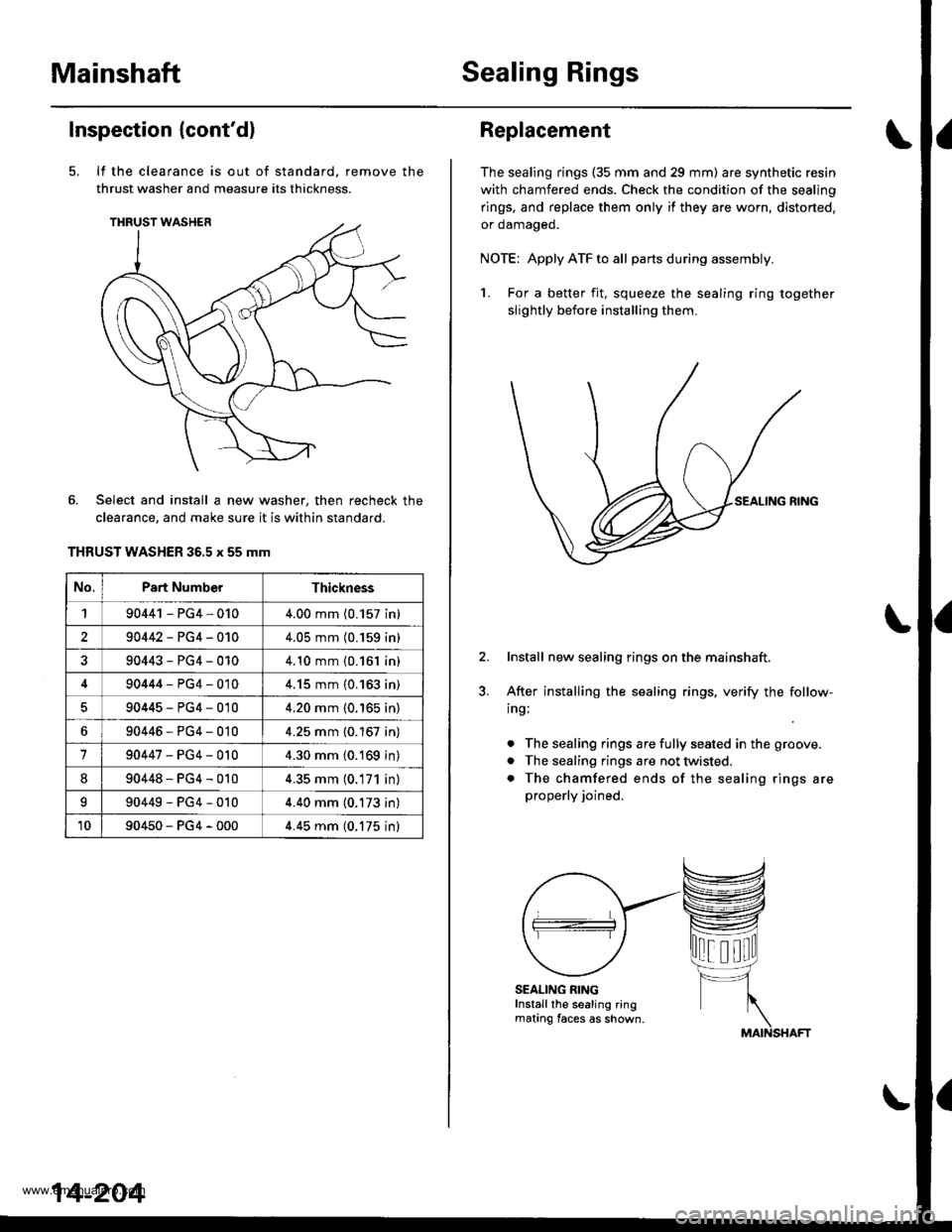
It the clearance is out of standard, remove the
thrust washer and measure its thickness.
Select and install a new washer, then recheck the
clearance, and make sure it is within standard.
THRUST WASHER 36.5 x 55 mm
No.Part NumberThickness
190441 - PG4,0104.00 mm (0.157 in)
290442-PG4-0104.05 mm (0.159 in)
90443-PG4-0104.10 mm {0.161 in)
90444-PG4-0104.15 mm {0.163 in)
90445-PG4-0104.20 mm (0.'165 in)
690446-PG4-0104.25 mm {0.167 in)
190447-PG4-0104.30 mm (0.169 in)
890448-PG4-0104.35 mm (0.171 in)
I90449-PG4-0104.40 mm (0.173 in)
1090450-PG4-0004.45 mm (0.175 inl
14-204
Replacement
The sealing rings (35 mm and 29 mm) are synthetic resin
with chamfered ends. Check the condition of the sealing
rings, and replace them only if they are worn, distorted,
or oamageo.
NOTE: Apply ATF to all partsduring assembly.
1. For a better fit, squeeze the sealing ring together
slightly before installing them.
Install new sealing rings on the mainshaft.
After installing the sealing rings, verify the follow-
ing:
. The sealing rings are fully seated in the groove.
. The sealing rings are not twisted.
. The chamfered ends of the sealing rings are
properly joined.
SEALING RINGInstall the sealing ringmating faces as shown.
www.emanualpro.com
Page 723 of 1395
3. Install the reverse selector hub on the countershaft
sub-assembly, and press the hub using the special
tool and a press as shown.
DRIVER to mm l.D.07746 - 0030100
REVERSE SEI.ICTORHUB
COUNTERSHAFTSU&ASSEMBLY
Inspection
Clearance Measurement
NOTE: Lubricate all parts with ATF during assembly.
1. Remove the countershaft bearing from the trans-
mission housing lsee page 14-227).
2. Assemble the countershaft parts using the special
tool and a press as described on this page. Do not
install the O-rings during inspection.
R€VERS€ SELECTORHUB
GEAR
NEEDLE BEARING
DISTANCE COLLAR, 28 mmSelective part
2NO GEAR
THRUST NEEDLE BEARING
GEAR
NEEOLE BEARING
GEAR COLIAR
THRUST NEEDLE BEARING
WASHER
CLUTCH ASSEMBLY
(cont'd)
14-207
www.emanualpro.com
Page 724 of 1395
Countershaft
Inspection (cont'd)
3.
4.
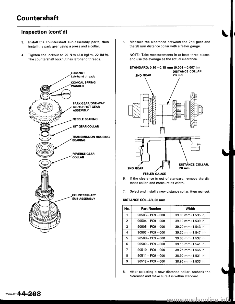
Install the countershaft sub-assembly parts, then
installthe park gear using a press and a collar.
Tighten the locknut to 29 N.m (3.0 kgf.m, 22 lbf.ft).
The countershaft locknut has left-hand threads.
LOCKNUTLe{t-hand threads
CONICAL SPRINGWASHER
PABK GEAR/ONE.WAYCLUTCH/1ST GEARASSEMBLY
NEEDLE BEANING
lST GEAR COLLAR
TRANSMISSION HOUSINGAEARING
REVERSE GEARCOLLAR
COUNTERSHAFTSUB.ASSEMBLY
14-208
5. Measure the clearance between the 2nd gear and
the 28 mm distance collar with a feeler gauge.
NOTE: Take measurements in at least three places,
and use the average as the actual clearance.
STANDARD: 0.10 - 0.18 mm (0.004 - 0.007 in)
OISTANCE COLLAR,28 mm
FEELER GAUGE
6. lf the clearance is out ot standard, remove the dis-
tance collar, and measure its width.
7. Select and install a new distance collar, then recheck.
DISTANCE COLLAR,28 mm
8. After selecting a new distance collar. recheck the
clearance and make sure it is within standard.
2NO GEAR
No.Part Numberwidrh
190503-PCg-00039.00 mm ('1.535 in)
290504-PCg-00039.'10 mm (1.539 in)
?90505-PCg-00039.20 mm {1.543 in)
90507-PCg-00039.30 mm (l.547 in)
90508*PCg-00039.05 mm (l.537 in)
90509-PCg-00039.15 mm (l.541 in)
790510-PCg-00039.25 mm {1.545 in)
890511-PCg-00038.90 mm { L531 in)
990512-PCg-00038.95 mm ( 1.533 in)
www.emanualpro.com
Page 737 of 1395
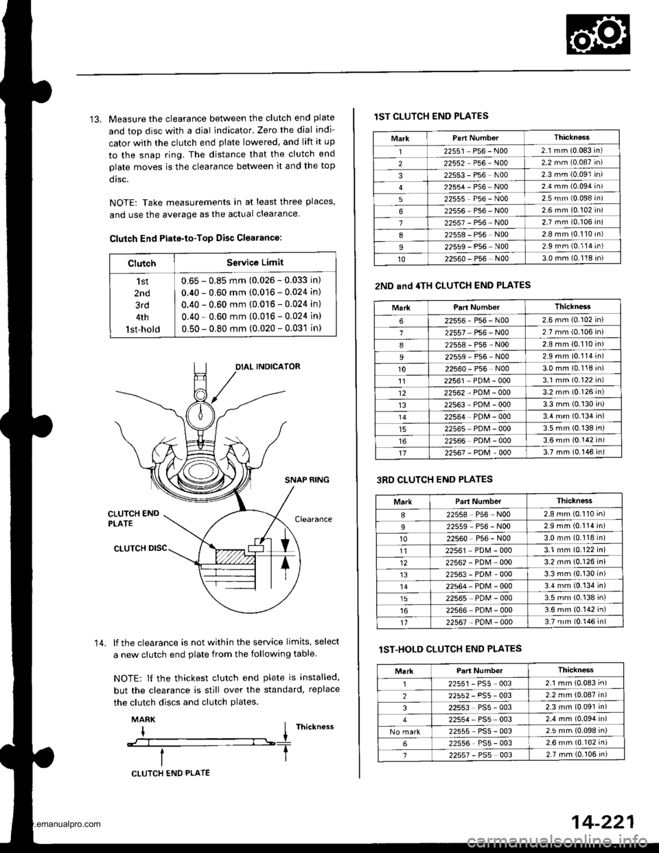
13. Measure the clearance between the clutch end plate
and top disc with a dial indicator. Zero the dial indi-
cator with the clutch end plate lowered, and lift it up
to the snap ring. The distance that the clutch end
plate moves is the clearance between it and the top
dtsc.
NOTE: Take measurements in at least three places'
and use the average as the actual clearance.
Clutch End Ptate-to-Top Disc Clearance:
ClutchService Limit
'l st
2nd
3rd
4th
lst-hold
0.65 - 0.85 mm (0.026 - 0.033 in)
0.40 - 0.60 mm (0.016 - 0.024 in)
0.40 - 0.60 mm (0.016 - 0.024 in)
0.40 - 0.60 mm (0.016 - 0.024 in)
0.50 - 0.80 mm (0.020 - 0.031 in)
SNAP RING
lf the clearance is not within the service limits, select
a new clutch end plate from the following table
NOTE: lf the thickest clutch end plate is installed,
but the clearance is still over the standard, replace
the clutch discs and clutch plates.
MARK
I I rnictness
--:--l----T
14.
CLUTCH END PLATE
14-221
lST CLUTCH END PLATES
2ND and 4TH CLUTCH END PLATES
3RD CLUTCH END PLATES
lST-HOLD CLUTCH END PLATES
MarkThicknass'I22551 P56 - N002.1 mm (0.083 in)
222552-P56-N002.2 mm (0.087 in)
322553 - P56 N002 3 mm (0.091 in)
22554-P56-NOo2.4 mm (0.094 in)
522555 P56 - N002.5 mm {0.098 in)
622556 P56 - N002 6 mm (0.102 in)
722557 - P56 N002.7 mm (0.106 in)
822558 - P56 N002.8 mm (0.110 in)
I22559 - P56 N002.9 rnm (0.114 in)
1022s60 - P56 N003.0 mm (0.118 in)
MarkParl NumberThickness
622556-P56-N002.6 mm (0.102 in)
122557 P56 - N002.7 mm (0.106 in)
822558-P56-N002.8 mm (0.110 in)
22559-P56-N002.9 mm (0.114 in)
1022560 - P56 N003.0 mm (0.118 in)'1122561 PDM - 0003.1 mm (0.122 inl
1222562 - PDM - 0003.2 mm {0.126 in)
1322563 PDM - 0003.3 mm (0.130 in)
22564 PDM - 0003.4 mm (0.134 in)
22565 PDM - 0003.5 mm (0.138 in)
22566 PDM - 0003.6 mm 10.142 in)
1722567-PDM-0003.7 mm (0.146 in)
MarkPart NumberThiclness
I22558 P56 - N002.8 mm (0.110 inl
922559 P56 - N002.9 mm (0.114 in)
1022560 P56 - N003.0 mm (0.118 in)
1122561 PD[4 - 0003.1 mm (0.122 in)
1222562 - PDM 0003.2 mm (0.126 in)
t322563-PDM-0003.3 mm (0.130 in)'1422564-PDN4-0003.4 mm (0.134 in)
1522565-PD[,l-0003.5 mm (0.138 in)
22566 PDM - 0003.6 mm (0.142 in)'t122567 - PoM - 0003.7 mm {0.146 in)
Thickness
2255r-PS5-0032.1 mm (0.083 in)
22552 - PS5- 0032.2 mm {0.087 in)
322553 PS5 - 0032.3 mm (0.091 in)
22554, PS5 - 0032.4 mm (0.094 in)
22555 PS5 - 0032.5 mm (0.098 in)
622556 PS5 - 0032.6 mm {0.102 in)
722557 - PSs 0032.7 mm (0.106 in)
www.emanualpro.com
Page 742 of 1395
Differential
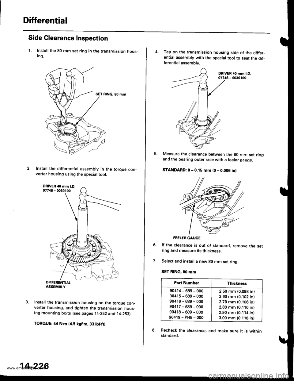
Side Clearance Inspection
1. Instsll the 80 mm set ring in the transmission hous-Ing,
SET RING, 80 mrn
Install the differential assembly in the torque con-verter housing using the specialtool.
Install the transmission housing on the torque con-verter housing, and tighten the transmission hous-ing mounting bolts (see pages 14-252 and t4-253).
TOROUE: 4a N.m l/r.5 kgf.m, 33 tbt.ftl
14-226
4. Tap on the transmission housing side of the diffsrential assembly with the special tool to seat the dif-ferential assemblv.
DBIVER ilo m.n LO.0t746 - 0030100
Measure the clearancs between the 80 mm set ringand the bearing outer race with a feeler gauge,
STANDARD: 0 - 0.15 mm (0 - 0.006 inl
FEEI..ER GAUGE
lf the clearance is out of standard, remove rne setring and measurs its thickness.
Select and instsll a new 80 mm set ring.
SET RING, 80 mm
Recheck the clearance, and make sure it is withinstandard.
7.
Part NumborThicknoss
90414-689-000
90415-689-000
90416-689-000
90417-689-000
90418-689-000
90419-PH8-000
2.50 mm (0.098 in)
2.60 mm (0.102 in)
2.70 mm (0.106 inl
2.80 mm (0.110 in)
2.90 mm (0.114 in)
3.00 mm (0. t'18 inl
www.emanualpro.com
Page 785 of 1395
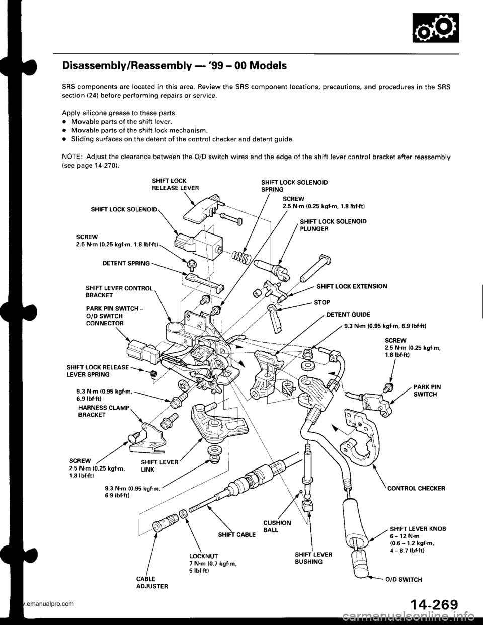
Disassembly/Reassembly -'99 - 00 Models
SRS components are located in this area. Review the SRS component locations, precautions, and procedures in the SRS
section (24) before performing repairs or service.
Apply silicone grease to these parts:
. Movable parts of the shift lever.
. Movable parts of the shift lock mechanism.
. Sliding surfaces on the detent of the control checker and detent guide.
NOTE: Adjustthe clearance between the O/D switch wires and the edge ofthe shift lever control bracket after reassembly(see page 14-270).
SHIFT LOCKRELEASE LEVERSHIFT LOCK SOLENOIDSPRING
SCREW2.5 N.m {0.25 kgf.m, 1.8lbtft)SHIFT LOCK SOLENOID
SCREW2.5 N.m (0.25 kgl.m, 1.8 lbl.ft)
SHIFT LOCK SOLENOIOPLUNGER
DETENT SPRING
SHIFT LEVER CONTROLBRACKET
PARK PIN SWITCH _
o/D swtTcHCONNECTOB
SHIFT LOCK EXTENSION
STOP
DETENT GUIDE
9.3 N.m {0.95 kgf.m, 6.9 lbl.ftl
SCREW2.5 N.m {0.25 kgt m,1.8 tbf.ftl
SHIFT LOCK BELEASELEVER SPRING
9.3 N.m {0.95 kgl.m,6.9 lbtfr)
HARNESS CLAMPERACKET
PARK PINswrTcH
SCREW2.5 N.m {0.25 kgf.m,1.8 tbl.f0
9.3 N.m 10.95 kgtm,6.9 tbf.ft)CONTROL CHECKER
SHIFT LEVER KNOB6- 12 N.m{0.6 - 1.2 kgt'm,4 - 8.7 tbnft)LOCKNUT7 N.m {0.7 kgl.m,5 tbf.ftl
SHIFT LEVERBUSHING
o/D swtTcH
14-269
www.emanualpro.com
Page 786 of 1395
Shift Lever
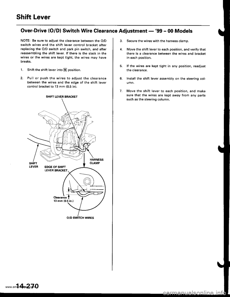
Over-Drive (O/Dl Switch Wire Clearance Adjustment -'99 - 00 Models
NOTE: Be sure to adjust the clearance between the O/D
switch wires and the shift lever control bracket after
replacing the O/D switch and park pin switch, and after
reassembling the shift lever. lf there is the slack in the
wires or the wires are kept tight, the wires may have
Dreaks.
1. Shift the shift lever into E positron.
2. Pull or push the wires to adjust the clearance
between the wires and the edge of the shift lever
control bracket to 13 mm (0.5 in).
SHIFT LEVER BRACKET
14-270
7.
Secure the wires with the harness clamp.
Move the shift lever to each position, and verify that
there is a clearance between the wires and bracket
in each position.
lf the wires are kept tight in any position, read.iust
the clearance.
Install the shift lever assembly on the steering col-
umn.
Move the shift lever to each position, and make
sure that the wires are kept away from any parts
such as the steering column.
www.emanualpro.com