Page 938 of 1395

Master Cylinder
I nspection/Disassembly
CAUTION: Do not spill brake fluid onthe vehicle; it may
damsge the paint; il brake fluid does contact th6 paint.
wash it off immodiately with water.
NOTE:
. Before reassembling, check that all parts are free of
dust and other foreign particles.
. Do not try to disassemble the master cylinder assem-
bly. Replace the master cylinder assembly with a new
pan it necessary,
. Make sure no dirt or other foreign matter is allowed
to contaminate the brake fluid.
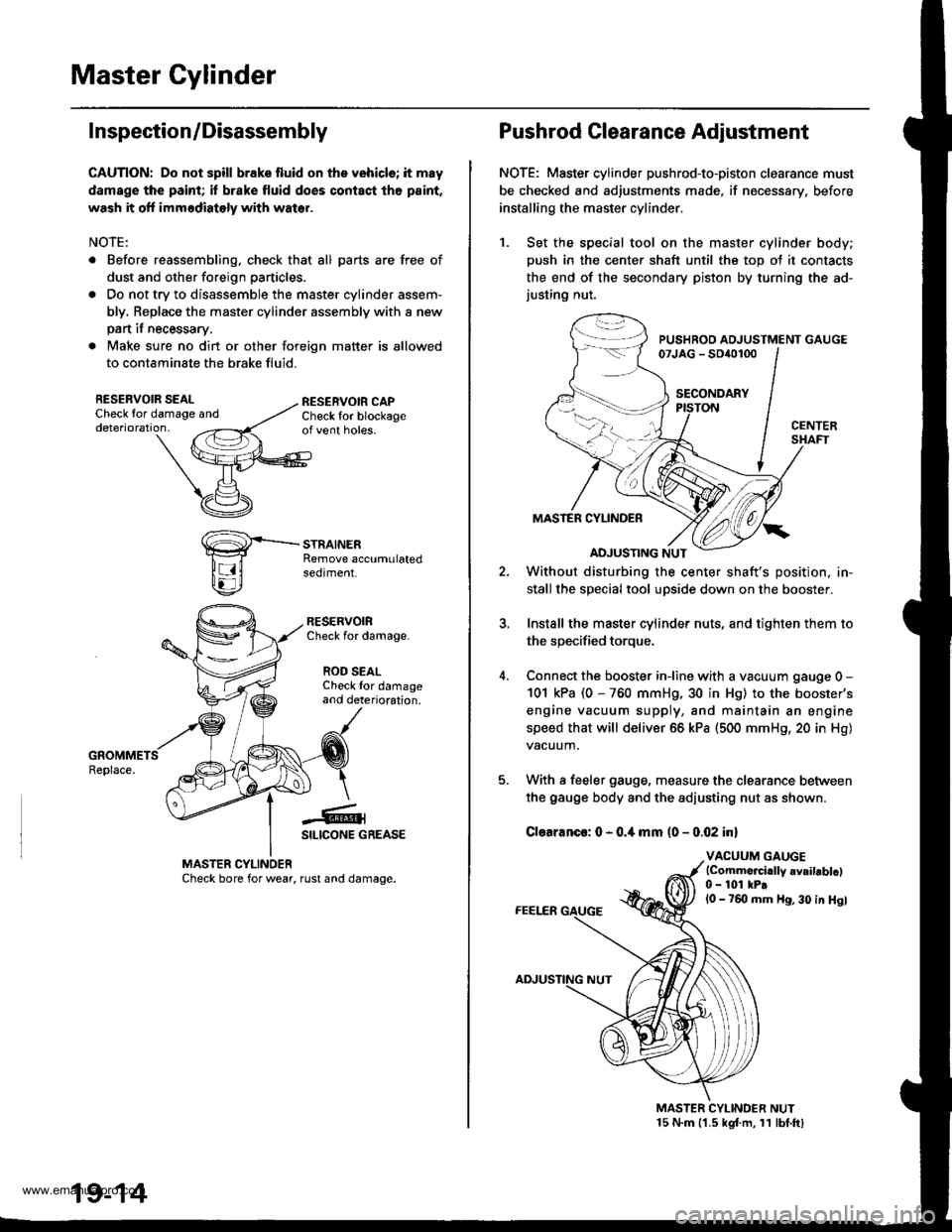
RESERVOIR SEALCheck for damaoe anddeterioration,
RESERVOIRCheck for damage.
ROD SEALCheck for damageand deterioration.
-€-1SILICONE GREASE
MASTER CYLINOERCheck bore for wear, rust and damage.
19-14
Pushrod Clearance Adjustment
NOTE: Master cylinder pushrod-to-piston clearance must
be checked and adjustments made, if necessary. before
installing the master cylinder.
1. Set the special tool on the master cylinder body;
push in the center shaft until the top ot it contacts
the end of the secondary piston by turning the ad-justing nut.
PUSHROD ADJUSTMENT GAUGE07JAG - SD{o100
SECONDARY
MASTER CYLINDER
ADJUSTING NUT
Without disturbing the center shaft's position, in-
stallthe special tool upside down on the booster.
Install the master cylinder nuts, and tighten them to
the sDecified toroue.
Connect the booster iniine with a vacuum gauge 0 -
101 kPa (0 - 760 mmHg, 30 in Hg) to the booster's
engine vacuum supply, and maintain an engine
speed that will deliver 66 kPa (500 mmH9, 20 in Hg)
vacuum.
With a feeler gauge, measure the clearance between
the gauge body and the adiusting nut as shown.
Clearanco: 0 - 0.4 mm (0 - 0.02 inl
VACUUM GAUGElCommo.cidly 6vailablcl0 - 101 kPtl0 - 760 mm Hg, 30 in Hgl
MASTER CYLINDER NUT15 N.m 11.5 kgt m, 11 lbt.ftl
www.emanualpro.com
Page 939 of 1395

6.
7.
8.
lf the clearance between the gauge body and
adjusting nut is 0.4 mm (0.02 in), the pushrod-to-
piston clearance is 0 mm. However. if the clearance
between the gauge body and adjusting nut is 0 mm,
the pushrod-to-piston clearance is 0.4 mm (0.02 in)
or more. Therefore it must be adjusted and
recheck€d.
lf clearance is incorrect, loosen the star locknut, and
turn the adjuster in or out to adjust.
. Adjust the clearance while the specified vacuum
is applied to the booster.
. Hold the clevis while adjusting.
Tighten the star locknut securely.
Remove the special tool.
0 - 0.4 mm (0 - 0.02 inl
Adjust the pushrod length as shown if the
is removed,
booster
11610.5 mm{4.6 t 0.02 inl
PUSHRODLOCKNUT1.5N.m 11.5 kgf.m. '11 lbtfl)
Install the master cylinder (see page 19-13).
9.
STAR LOCKNUT22 N.m12.2 kgt m. 16 lbtftl
10.
(Check valve is built-in)
Brake Booster Inspection
FunctionalTest
1. With the engine stopped, press the brake pedal sev-
eral times to deplete the vacuum reservoir. thenpress the pedal hard, and hold it for 15 seconds. lf
the pedal sinks, either the master cylinder is
bypassing internally, or the brake system (master
cylinder, lines, modulator, proportioning valve. or
caliper) is leaking.
2. Start the engine with the pedal pressed. lf the pedal
sinks slightly. the vacuum booster is operating nor-
mally. lf the pedal height does not vary, the booster
or check valve is faultv.
3. With the engine running, press the brake pedal light-
ly. Apply just enough pressure to hold back auto-
matic transmission creep. lf the brake pedal sinks
more than 10 mm (3/8 in.) in three minutes, the mas-
ter cylinder is faulty. A slight change in pedal height
when the Ay'C compressor cycles on and off is nor-
mal. (The Ay'C compressor load changes the vacuum
available to the booster.)
Leak Test
1.Press the brake pedal with the engine running, then
stop the engine. lf the pedal height does not vary
while pressed for 30 seconds, the vacuum booster is
OK. lf the pedal rises, the booster is faulty.
With the engine stopped, press the brake pedal sev-
eral times using normal pressure. When the pedal is
first pressed. it should be low, On consecutive appli-
cations, the pedal height should gradually rise. lf thepedal position does not vary. check the booster
check valve.
Boostor Chock Valve Test
1. Disconnect the brake booster vacuum hose at the
booster.
2. Start the engine, and let it idle. There should be vac-
uum. lf no vacuum is available, the check valve is
not working properly. Replace the brake booster
vacuum hose and check valve. and retest.
ERAKE BOOSTERVACUUM HOSE
www.emanualpro.com
Page 992 of 1395

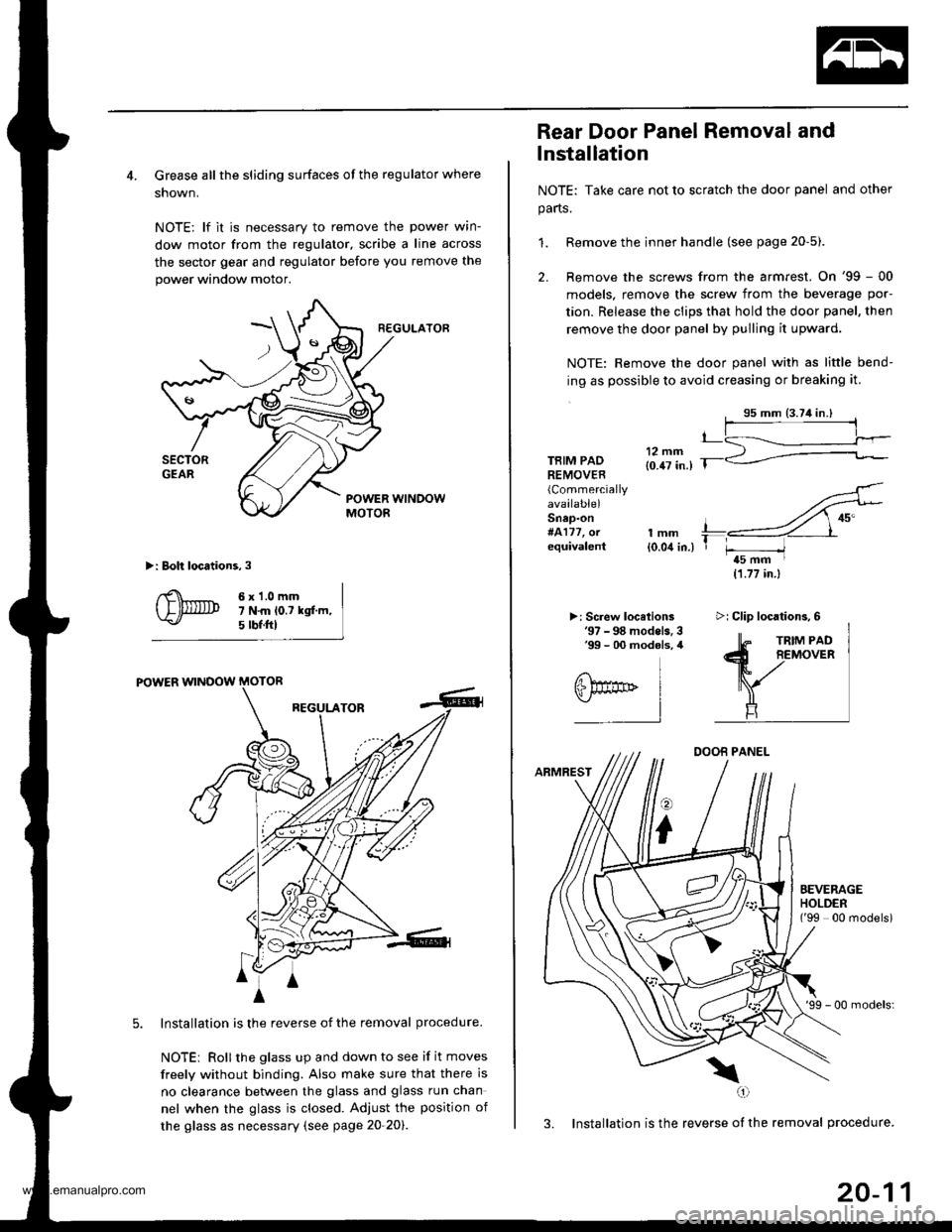
4. Grease all the sliding surfaces of the regulator where
shown.
NOTE: lf it is necessary to remove the power wrn-
dow motor from the regulator, scribe a line across
the sector gear and regulator before you remove the
power window motor.
R€GULATOF
>: Boh locations,3
6x1.0mm7 N.m lo.t kgf.m,5 tbf.ftl
POWER WINOOW MOTOR
REGULATOR
Installation is the reverse of the removal procedure.
NOTEi Rollthe glass up and down to see if it moves
freely without binding. Also make sure that there is
no clearance betlveen the glass and glass run chan
nel when the glass is closed. Adjust the position of
the glass as necessary (see page 20-20).
4
A
m^i
A
Rear Door Panel Removal and
lnstallation
NOTE: Take care not to scratch the door panel and other
parts.
1. Remove the inner handle (see page 20-5).
2. Remove the screws from the armrest. On '99 - 00
models, remove the screw from the beverage por-
tion. Release the clips that hold the door panel, then
remove the door panel by pulling it upward.
NOTE: Remove the door panel with as little bend-
ing as possible to avoid creasing or breaking it.
TBIM PADREMOVER(Commercially
available)Snap-on#4177, orequivalentlmm{0.04 in.)
>: Screw locelions'97 - 98 models. 3'99 - 00 modols, 4
11.77 in.)
DOOB PANEL
ARMREST
o
i
'99 - 00 models:
3. Installation is the reverse of the removal procedure.
\(,1
t_
T r-----/t5 mm I
EEVERAGEHOLDEN('99 00 modelsi
>i Clip locations,6
20-11
www.emanualpro.com
Page 996 of 1395

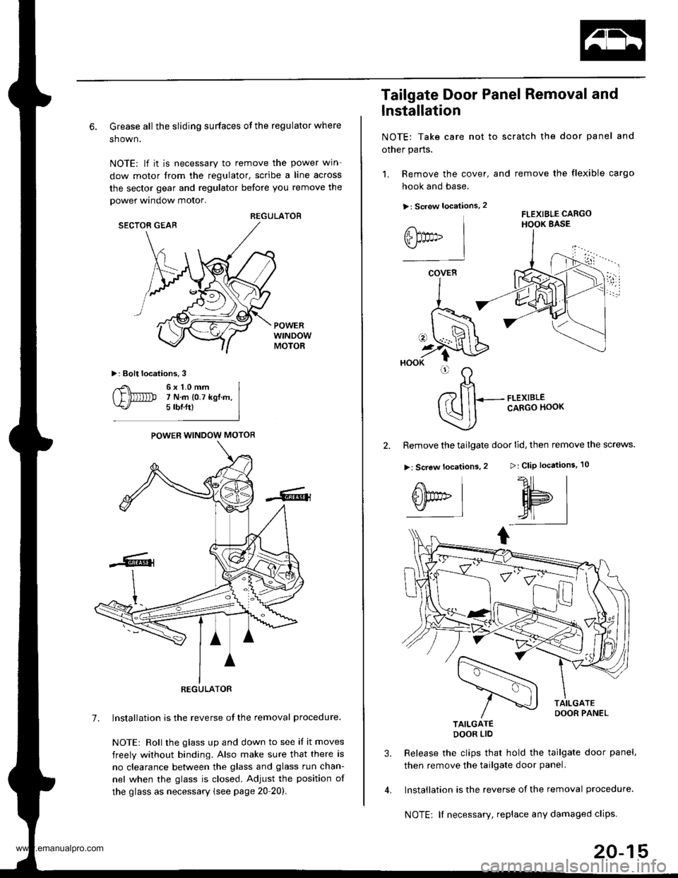
6. Grease all the sliding surfaces of the regulator where
shown.
NOTE: lf it is necessary to remove the power win-
dow motor from the regulator, scribe a line across
the sector gear and regulator before you remove the
power window motor.
REGULATORSECTOR GEAB
POWERwtNDowMOTOR
>: Bolt locations.3
6x1.0mm7 N.m 10.7 kgf.m,5 rbnftl
POWER WINDOW MOTOR
REGULATOR
7. lnstallation is the reverse of the removal procedure.
NOTEr Roll the glass up and down to see if it moves
freely without binding. Also make sure that there is
no clearance between the glass and glass run chan-
nel when the glass is closed. Adjust the position of
the glass as necessary {see page 20 20).
1. Remove the cover,
hook and base.
>: Screw locations.2
Tailgate Door Panel Removal and
lnstallation
NOTE: Take care not to scratch the door panel and
other parts.
and remove the flexible cargo
FLEXIBLE CARGOHOOK BASE
>: CliP locations.
?11 |
HPI,4| |
I
FLEXIBLECARGO HOOK
2. Remove the tailgate door lid, then remove the screws.
>: Screw locations.2
TAILGATEDOOR LIO
Release the clips that hold the tailgate door panel,
then remove the tailgate door panel.
Installation is the reverse of the removal procedure.
NOTE: lf necessary, replace any damaged clips.
3.
@t"
COVER
i
20-15
www.emanualpro.com
Page 1155 of 1395

Clutch Inspection
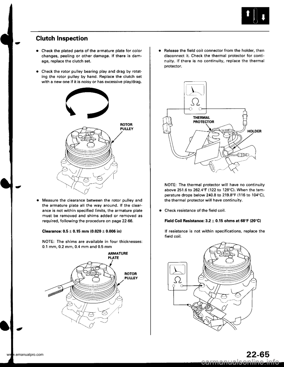
Check the plated parts of the armature plate for color
changes, peeling or other damage. lf there is dam-
age, replace the clutch set.
Check the rotor pulley bearing play and drag by rotat-
ing the rotor pulley by hand. Replace the clutch set
with a new one if it is noisy or has excessive play/drag.
Measure the clearance between the rotor pulley and
the armature plate all the way around. lf the clear-
ance is not within specified limits, the armature plate
must be removed and shims added or removed as
required, following the procedure on page 22-66.
Cloarance: 0.5 t 0.15 mm {0.020 t 0.q)6 in)
NOTE: The shims are available in four thicknesses:
0.1 mm. 0.2 mm. 0.4 mm and 0.5 mm
ABMATUBE
ROTOR
. Release the field coil connector from the holder, then
disconnect it. Check the thermal protector for conti-
nuity, lf there is no continuity, replace the thermal
prorecror.
NOTE: The thermal protector will have no continuity
above 251.6 to 262.4"F 1122 to 128"C). When the tem-perature drops below 240.8 to 219.8"F (116 to 104'C),
the thermal protector will have continuity.
Check resistance of the field coil.
Field Coil Resistance: 3.2 i 0.15 ohms at 68"F {20'C)
lf resistance is not within specifications, replace the
field coil.
22-65
www.emanualpro.com