1997 HONDA CR-V Meter
[x] Cancel search: MeterPage 677 of 1395

Pressure Testing
Changing
NOTE: Keep all foreign particles out of the transmis-
sion.
1. Bring the transmission up to operating temperature
(the radiator fan comes on) by driving the vehicle.
Park the vehicle on level ground. turn the engane
off. then remove the drain Plug.
NOTE: lf a cooler flusher is to be used, see page
14-264 and 14-265.
TRANSMISSIONEND COVER
DRAIN18 x 1.5 mmSEALING WASHEBReplace.49 N.m {5.0 kgt.m, 36 lbf.tl)
Reinstall the drain plug with a new sealing washer,
then refill the transmission with the recommended
fluid to the uDper mark on the dipstick. Always use
Genuine Honda Premium Formula Automatic
Transmission Fluid (ATF) Using a non-Honda ATF
can affect shift quality.
Automatic Transmission Fluid Capacity:
4WD;
2.9 { (3.1 US qt. 2.6 lmp qt) 8t change
5.8 ? {7.2 US $, 6.0 lmp qt} at ovethaul
2WD:
2.7 | l2.S US qt,2.1lmp qtl ai change
5.9 ? {6.2 US $, 5.2 lmp qtl at ovolhaul
2.
a
a
1.
Wlrile testing, be careful of the rotaling wheols.
Mako sure lifts, iacks, and safety stands ar€ placed
properly (see scction 11.
Before testing, be sure the transmission fluid is
filled to the proPer level.
4WD:
Raise the vehicle (see section 11.
2WD:
Raise the front of the vehicle, and make sure it is
securely supported. Set the parking brake, and block
both rear wheels securely.
Allow all four wheels {4WD) or front wheels (2wD}
to rotate freely.
Warm up the engine (the radiator fan comes on),
then stop it and connect the tachometer.
Connect the oil pressure gauges to each inspection
hole securely, and do not allow dust or other foreign
particles to enter the inspection holes.
TOROUE: 18 N'm ll.8 kgf'm, 13 lbf'ft)
5.
A/T PRESSURE HOS€,2210 mm07MAJ - PYiOllA
{4 Requircd}
,4'/"' ,a
W'
A/T PRESSURE HOSEADAPTER07MAJ - PYt0120(il Rcquiledl
6. Measure the following Pressure:. Line Pressure ..........,14-162
. 1st. 1st-hold Clutch Pressure .............'. 14-162
. 2nd,3rd and 4th Clutch Pressure .......... 14-163
7. Install new sealing washers and the sealing bolts in
the inspection holes, and tighten to the specified
toroue.
(cont'd)
A/T OIL PRESSUREGAUGE SET W/PANEL07{06 - 0020400
/4\\-J-- (
+..\.-.\-'-\
A/T LOW PBESSUREGAUGE w/PANEL07406 - 0070300
TOROUE: 18 N'm 11.8 kgf'm, 13 lbf'ft)
14-161
www.emanualpro.com
Page 738 of 1395
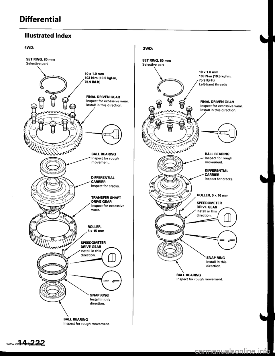
Differential
lllustrated Index
'lWD:
SET RING, 80 mmSelective part
10 x 1.0 mm103 N.m (10.5 kgt.m,?5.9 tbtftl
FINAL ORIVEN GEARlnspect for excessive wear,Install in this direction.
BALL BEARINGInspect for rough
DIFFERENTIAI.CARRIERlnspect for cracks.
TRANSFER SHAETDNlvE GEARInspect for excessive
SPEEDOMETERDRIVE GEARInstall in thisdirection.
SNAP RINGInstall in thisdirection.
BALL BEARINGInspect for rough movement,
14-222
2WDl
SET nlNG, 80 mmSel6ctive part
A,U
,gBc
10 x 1.0 mm103 N.m {10.5 kg[.m,75.9 tbt.ftlLeft-hand threads
FINAL ORIVEN GEARInspect for excessive wear,Install in thls direction.
BALL BEABINGInspect for rough
DIFFERENTIAI.CARRIERInspect for cracks.
ROLLER,5 x 10 mm
SPEEDOMETERDRIVE GEARInstall in thisdirection.
SNAP RINGInstall in thisdirection.
BALL BEARING
www.emanualpro.com
Page 740 of 1395
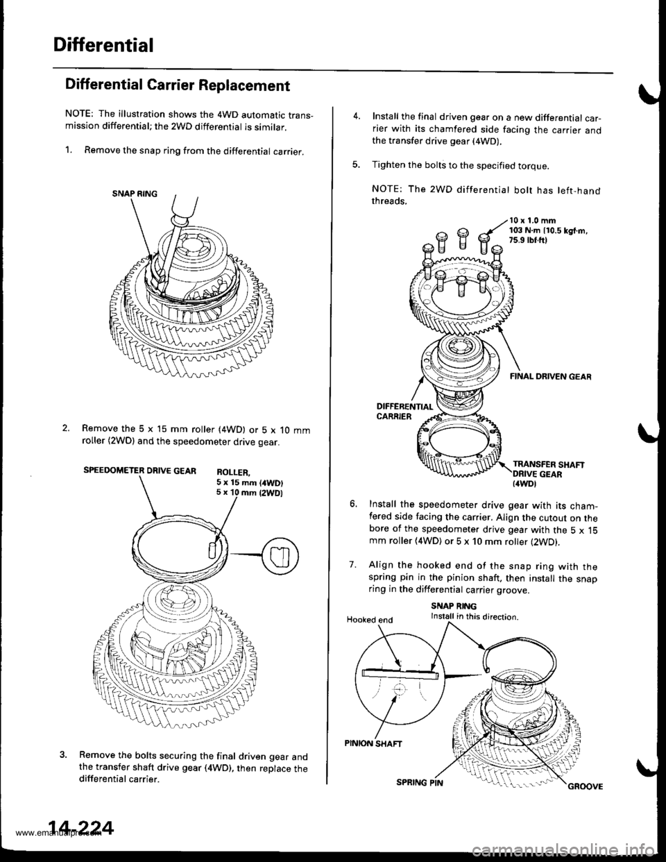
Differential
Differential Carrier Replacement
NOTE: The illustration shows the 4WD automatic trans-mission differential; the 2WD differential is similar.
1. Remove the snap ring from the differential carrier.
Remove the 5 x 15 mm roller (4WD) or 5 x 10 mmroller (2WDl and the speedometer drive gear.
SPEEDOMETER DRIVE GEAR RoI I FP
Remove the bolts securing the final driven gear andthe transfer shaft drive gear (4WD), then replace thedifferential carrier.
5 x 15 mm (/tWD)5 x 10 mm {2WDl
14-224
SPRING PINGROOVE
Install the final driven gear on a new differential car-rier with its chamfered side facing the carrier andthe transfer drive gear (4WD),
Tighten the bolts to the specified torque.
NOTE: The 2WD differentiat bolt has left-handthreads,
10 x 1.0 mm103 N.m 110.5 kd.m,7s.9 rbr.ft)
7.
FINAL DRIVEN GEAR
TRANSFER SHAFT
Install the speedometer drive gear with its cham-fered side facing the carrier. Align the cutout on thebore of the speedometer drive gear with the 5 x 15mm roller (4WD) or 5 x 10 mm roller (2WD).
Align the hooked end of the snap ring with thespring pin in the pinion shaft. then install the snaoring in the differential carrier groove
SNAP RINGInstall in this direction.Hooked end
PINION SHAFT
{4WDl
www.emanualpro.com
Page 860 of 1395
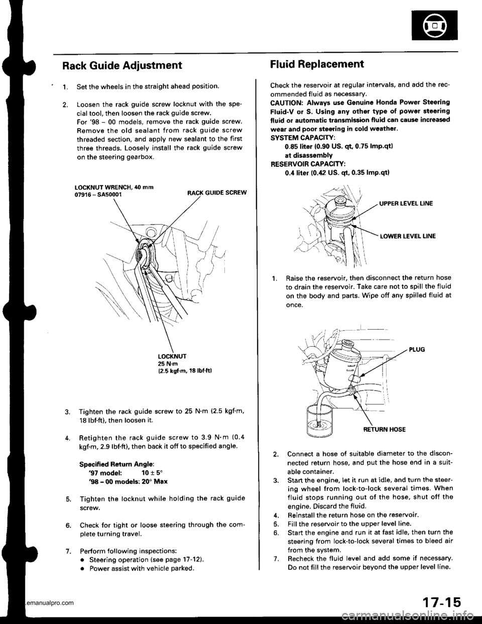
Rack Guide Adjustment
1.
6.
7.
5.
4.
Set the wheels in the straight ahead position.
Loosen the rack guide screw locknut with the spe-
cialtool, then loosen the rack guide screw.
For'98 - 00 models, remove the rack guide screw.
Remove the old sealant from rack guide screw
threaded section, and apply new sealant to the first
three threads. Loosely install the rack guide screw
on the steering gearbox.
RACK GUIDE SCREW
LOCKNUT25 N.m
12.5 kgt m, 18lbtftl
Tighten the rack guide screw to 25 N.m (2.5 kgf'm,
18 lbf.ft), then loosen it.
Retighten the rack guide screw to 3.9 N'm (0.4
kgf.m, 2.9 lbf.ft), then back it off to specified angle.
Specified Return Anglo:
37 model: 10 r 5"'98 - 00 modeb: 20' Max
Tighten the locknut while holding the rack guide
screw.
Check for tight or loose steering through the com-
plete turning travel.
Perform following inspections:
. Steering operation (see page 17-12).
. Power assist with vehicle parked
Fluid Replacement
Check the reseryoir at regular intervals, and add the rec-
ommended fluid as necessary.
CAUTION: Always use Gsnuine Honda Power Steering
Fluid-V or S. Using any other type of power steering
tluid or automatic transmission fluid can cause increassd
wear and poor steering in cold w3athel.
SYSTEM CAPACITY:
0.85 liter {0.90 US. qt. 0.75 lmp.qtl
at disasssmbly
RESERVOIR CAPACITY:
0.,1 liter (0.42 US. gt, 0.35 lmp.qi)
UPPEN LEVEL LINE
LOWER LEVEL LINE
1.Raise the reservoir. then disconnect the return hose
to drain the reservoir. Take care not to spill the fluid
on the body and parts. Wipe off any spilled fluid at
once.
2, Connect a hose of suitable diameter to the discon-
nected return hose, and put the hose end in a suit-
able container.
3. Stan the engine. let it run at idle, and turn the steer-
ing wheel from lock-to-lock several times. When
fluid stops running out of the hose, shut off the
engine. Discard the fluid.
4. Beinstallthe return hose on the reservoar.
5. Fill the reservoir to the upper level line,
6. Start the engine and run it at fast idle. then turn the
steering from lock-to-lock several times to bleed air
from the system.
7. Recheck the fluid level and add some if necessary.
Do not fill the reservoir beyond the upper level line.
www.emanualpro.com
Page 881 of 1395
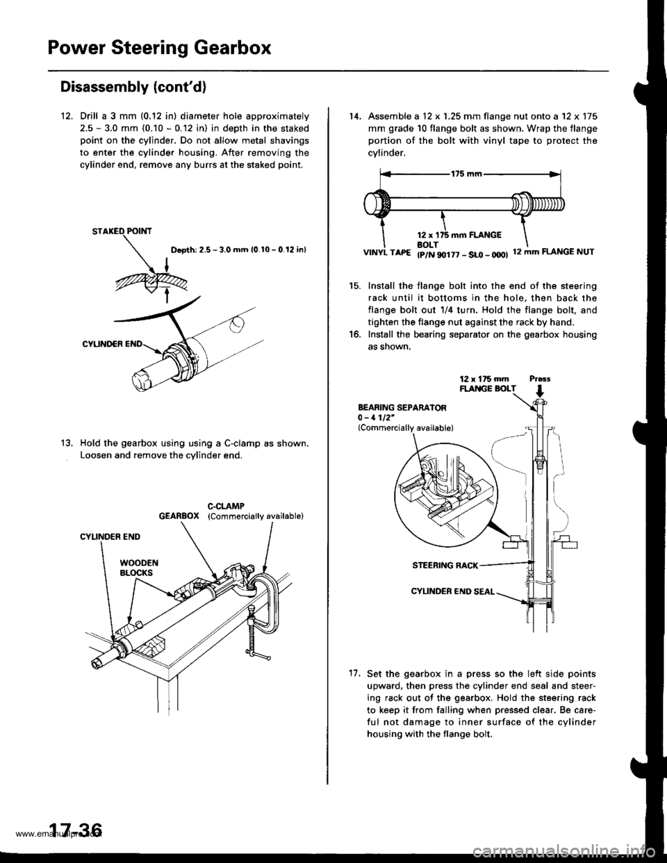
Power Steering Gearbox
Disassembly {cont'd}
12. Drill a 3 mm (0.12 in) diameter hole approximately
2.5 - 3.0 mm (0.10 - 0.12 in) in depth in the staked
point on the cylinder. Do not allow metal shavings
to enter the cylinder housing. After removing the
cylinder end, remove any burrs at the staked point.
D.oth: 2.5 - 3.0 mm 10.10 - 0.12 inl
CYUNOER
Hold the gearbox using using a C-clamp as shown,
Loosen and remove the cvlinder end.
13.
17-36
14, Assemble a 12 x 1.25 mm flange nut onto a '12 x 175
mm grade 10 flange bolt as shown, Wrap the flange
portion of the bolt with vinyl tape to protect the
cvlinder,
VINYL TAP€ tp/N 90177 - SLO - OOOI 12mmFLANGENUT
Install the flange bolt into the end of the steering
rack until it bottoms in the hole. then back the
flange bolt out 1/4 turn. Hold the flange bolt, and
tighten the flange nut against the rack by hand.
Install the bearing separator on the gearbox housing
as snown.
15.
BEARING SEPARATOR0 - 1112'(Commercially available)
17.
STEERING RACK
CYLINDER €ND
Set the gearbox in a press so the lelt side points
upward, then press the cylinder end seal and steer-
ing rack out of the gearbox. Hold the steering rack
to keep it from falling when pressed clear. Be care-
ful not damage to inner surface of the cylinder
housing with the flange bolt.
www.emanualpro.com
Page 886 of 1395
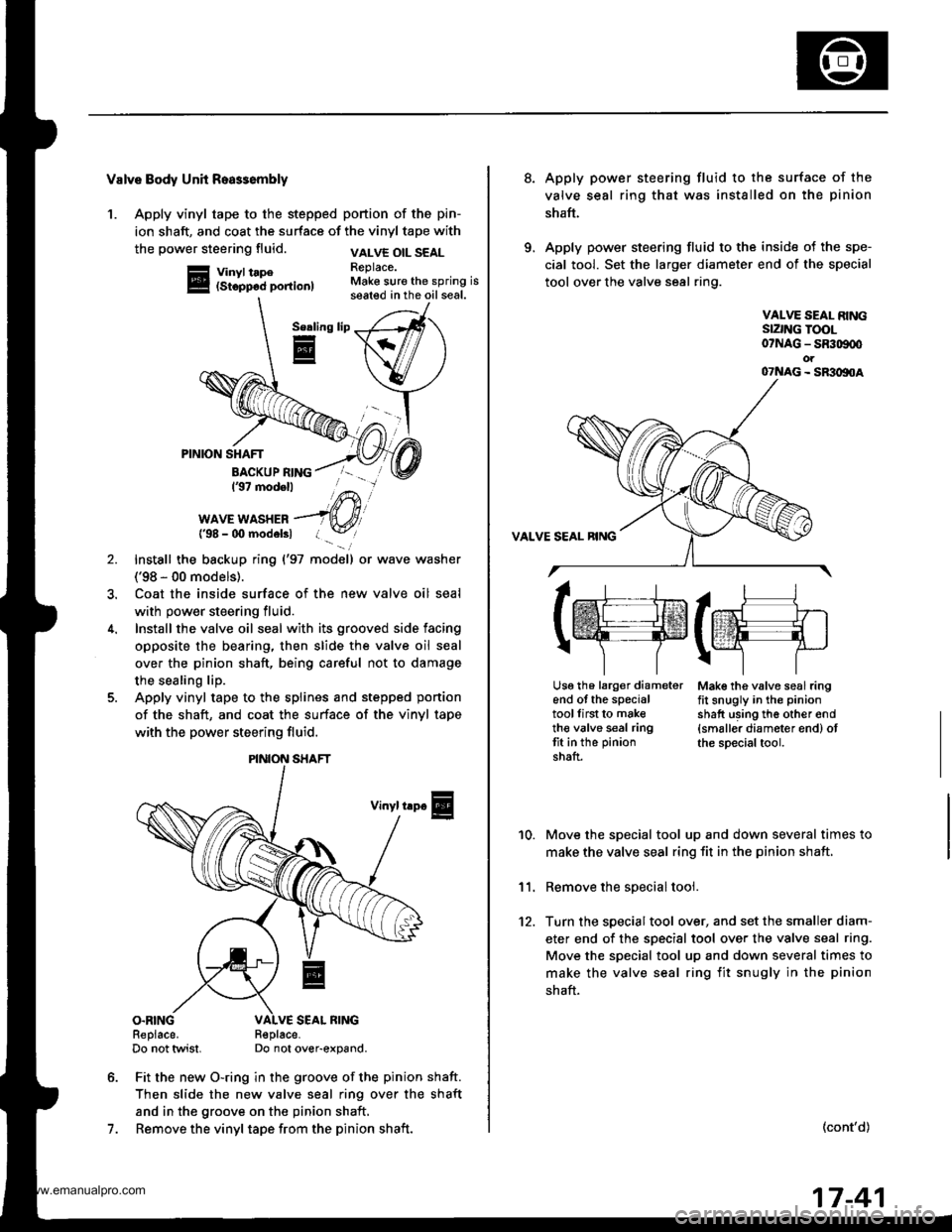
Valve Body Unh Roa$embly
1. Apply vinyl tape to the stepped portion of the pin-
ion shaft, and coat the surface of the vinyl tape with
the power steering fluid.
Vinyl tape(Stopp6d portion)
VALVE OIL SEALReplace.Make sure the spring isseated in the oil seal.
Serling
E
7.
PINION SHAFT
BACKUP RING137 modell
WAVE WASHER{'98 - 00 modelsl
Install the backup ring {'97 model) or wave washer
('98 - 00 models).
Coat the inside surface of the new valve oil seal
with power steering fluid.
Install the valve oil seal with its grooved side facing
opposite the bearing, then slide the valve oil seal
over the pinion shaft, being careful not to damage
the sealing lip.
Apply vinyl tape to the splines and stepped ponion
of the shaft, and coat the surface of the vinyl tape
with the power steering fluid.
Vinyl trp€
O.RINGReplace.Do not twist.R€place-Do not over-expand.
Fit the new O-ring in the groove of the pinion shaft.
Then slide the new valve seal ring over the shaft
and in the groove on the pinion shaft,
Remove the vinyl tape from the pinion shaft.
\/
PINION SHAFT
8.Apply power steering fluid to the surface of the
valve seal ring that was installed on the pinion
shaft.
Apply power steering fluid to the inside of the spe-
cial tool. Set the larger diameter end of the special
tool over the valve seal ring.
VALVE SEAL RINGSIZNG TOOL07NAG - SR309q'ot07NAG - SR3oltoA
Mak€ the valve seal ringfit snugly in the pinion
shatt using th6 other end{smaller diameter end) otthe special tool.
10.
11.
12.
Move the special tool up and down several times to
make the valve seal ring fit in the pinion shaft,
Remove the soecial tool.
Turn the special tool over, and set the smaller diam-
eter end of the specisl tool over the valve seal ring.
Move the special tool up and down several times to
make the valve seal ring fit snugly in the pinion
shaft.
(cont'd)
lrr.rj1
tffifrE-rr.]
r\-''] 7
Usg th6 larg€r diameterend of the specialtoollirst to maketh€ valve seal ringtit in the pinion
shaft.
17-41
www.emanualpro.com
Page 887 of 1395
Power Steering Gearbox
13.
Reassembly (cont'd)
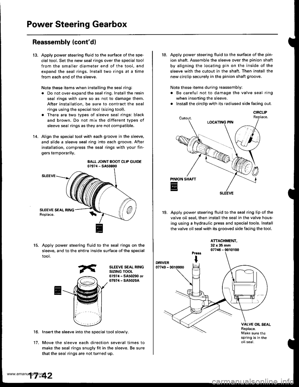
Apply power steering fluid to the surface of the spe-
cial tool. Set the new seal rings over the special tool
from the smaller diameter end of the tool. and
expand the seal rings. Install two rings at a time
Jrom each end ofthe sleeve.
Note these items when installing the seal ring:
. Do not over-expand the seal ring. Install the resin
seal rings with care so as not to damage them.
After installation, be sure to contract the seal
rings using the specialtool {sizing tool).
. There are two types of sleeve seal rings: black
and brown. Do not mix the different types of
sleeve seal rings as they are not compatible.
Align the special tool with each groove in the sleeve,
and slide a sleeve seal ring into each groove. After
installation, compress the seal rings with your fin-
gers temporarily.
BALL JOINT BOOT CLIP GUIDE07974 - SA508q)
SLEEVE
Apply power steering fluid to the seal rings on the
sleeve, and to the ehtire inside surface of the special
tool.
14.
15.
SLEEVE SEAL RINGSIZING TOOL07974 - SA502O0 or07974 - SA5020A
16.Insert the sleeve into the special tool slowly.
Move the sleeve each direction several times to
make the seal rings snugly fit in the sleeve. Be sure
that the seal rings are not turned up,
't1.
18. Apply power steering fluid to the surface of the pin-
ion shaft. Assemble the sleeve over the Dinion shaft
by aligning the locating pin on the inside of the
sleeve with the cutout in the shaft. Then install the
new circlip securely in the pinion shaft groove.
Note these items during reassembly:
. Be caretul not to damage the valve seal ring
when inserting the sleeve.
. Install the circlip with its radiused side facing out.
Apply power steering fluid to the seal ring lip of the
valve oil seal. then install the seal in the valve hous-
ing using a hydraulic press and special tools. Install
the valve oil seal with its grooved side facing the tool.
19.
ATTACHMENT,32x35mm077i16 - (x)10100
VALVE OIL SEALReplace.Make sure thespring is in theoilseal.
CIRCLIP
www.emanualpro.com
Page 891 of 1395
Power Steering Gearbox
Reassembly (cont'dl
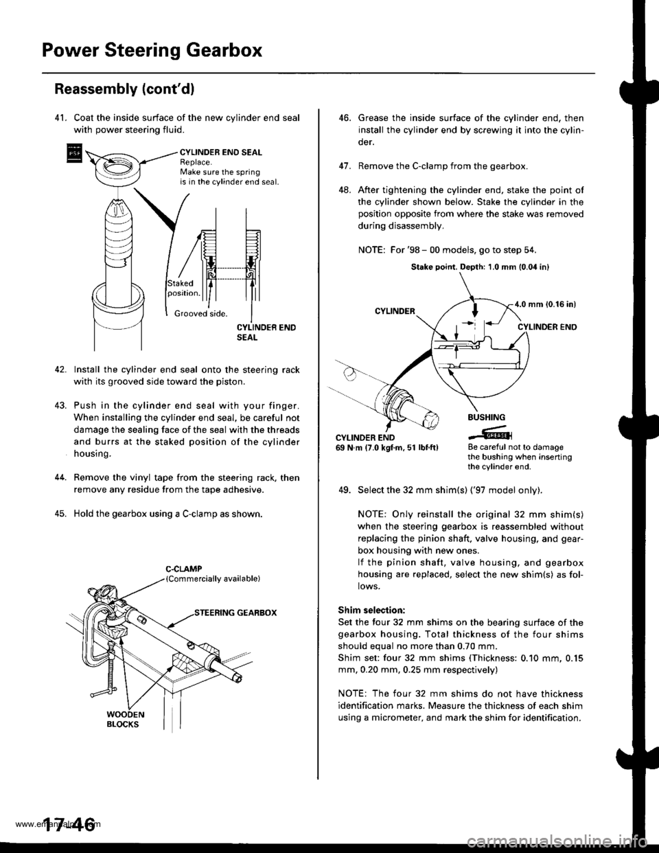
4l. Coat the inside surface of the new cvlinder end seal
with power steering fluid.
CYLINDEB ENO SEALReplace.Make sure the springis in the cylinder end seal.
43.
Stakedposrtron.
Grooved side.
42. Install the cylinder end seal onto the steering rack
with its grooved side toward the piston.
Push in the cylinder end seal with your finger.
When installing the cylinder end seal, be careful not
damage the sealing face of the seal with the threads
and burrs at the staked position of the cylinder
housing.
Remove the vinyl tape from the steering rack, then
remove any residue from the tape adhesive.
Hold the gearbox using a C-clamp as shown.
GEARBOX
44.
45.
C.CLAMP
17-46
46.Grease the inside surtace of the cylinder end, then
install the cylinder end by screwing it into the cylin-
der.
Remove the C-clamp from the gearbox.
After tightening the cylinder end, stake the point of
the cylinder shown below. Stake the cylinder in the
position opposite from where the stake was removed
during disassembly,
NOTE: For '98 - 00 models, go to step 54.
41.
48.
BUSHING
-tGCYLINDER END69 N.m (7.0 kgf.m,51 lbtft)8e careful not to damagethe bushing when insertingthe cylinder end.
49. Select the 32 mm shim(s) ('97 model onlv).
NOTE: Only reinstall the original 32 mm shim(s)
when the steering gearbox is reassembled without
replacing the pinion shaft. valve housing, and gear-
box housing with new ones.
lf the pinion shaft, valve housing, and gearbox
housing are replaced, select the new shim{s) as fol-
lows.
Shim selection:
Set the four 32 mm shims on the bearing surface of the
gearbox housing. Total thickness of the four shims
should equal no more than 0.70 mm.
Shim set: four 32 mm shims (Thickness: 0.10 mm, 0.15
mm, 0.20 mm, 0.25 mm respectively)
NOTE: The four 32 mm shims do not have thickness
identification marks. Measure the thickness of each shim
using a micrometer, and mark the shim for identification.
Stake point, Depth: 1,0 mm (0.04 inl
4.0 mm {0.16 in)
www.emanualpro.com