Page 1062 of 1395
Adjustment
NOTE:
. After adjusting the tailgate door, adjust the rear hatch glass.
. Loosen the striker mounting bolts slightly.
. Remove the rear spoiler, and remove the support strut from body side.
1. Loosen the rear hatch glass mounting nuts.
2. Adjust the rear hatch glass so there are equal gaps between the rear hatch glass, the taillights, and the tailgate door.
NOTE: lf necessary, loosen the rear hatch glass hinge mounting nuts and move the rear hatch glass backward or for-
ward to fit the rear weatherstrip and tailgate door weatherstrip.
REAR HATCI{GLASS HINGES
REAR HATCH GLASS HINGEMOUNTING NUT6x1.0mm9.8 N.m (1.0 kgf.m,7.2 tbt f Remove the rear edgeotthe headliner(see page 20-44).
MOUNTING NUT6x1.0mm9.8 N.m 11.0 kgtm,7.2 rbf.ftt
Taillight side:Tailgate door side:
About7mm
1o.27 in.l
NOTE: Adjust for equal gapsbetween the right and left.TCH GLASSIHAREAR
(cont'd)
20-81
www.emanualpro.com
Page 1063 of 1395

Rear Hatch Glass
3.
4.
Adjustment (cont'dl
After adjusting the rear hatch glass, tighten the rear hatch glass mounting nuts, and installthe support strut.
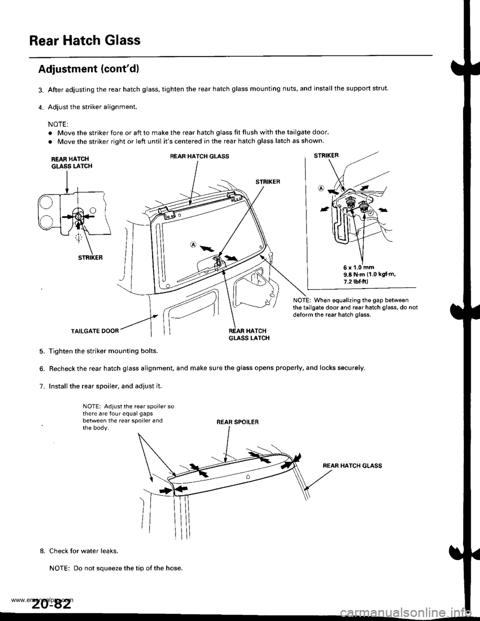
Adjust the striker alignment.
NOTE:
. Move the striker fore or aft to make the rear hatch glass fit flush with the tailgate door'
. Move the striker right or left until it's centered in the rear hatch glass latch as shown.
REAR HATCHGLASS LATCH
STRIKER
NOTE: When equalizing the gap betweenthe tailgate door and rear hatch glass, do notdglorm the rear hatch glass.
TAILGATE DOOR
5. Tighten the striker mounting bolts.
6. Recheck the rear hatch glass alignment. and make sure the glass opens properly, and locks securely.
7. Installthe rear spoiler. and adjust it.
NOTE: Adjust the rear spoiler sothere are four equal gaps
between the rear spoiler andthe body.REAR SPOILER
REAR HATCH GLASS
8. Check for water leaks.
NOTE: Do not squeeze the tip of the hose.
20-82
REAR HATCH GLASS
6x1.0mm9.8 N.m (1.0 kgt'm,
7.2tbl.ftl
www.emanualpro.com
Page 1066 of 1395
Door Moldings Replacement
CAUTION:
. Put on gloves to protect your hands.. When prying with a flat-tip scrowdriver, wrap it with prot€stive tape to provent damag€.
NOTE:
. Take care not to scratch the body.. Be careful not to damage the front and rear door moldings.
t
Adhesive aleas,
Adhesive area.FRONT DOORMOLDINGREAR DOOBMOLDING
a: Plastic nut location, 1
(cont'd)
20-85
>: Clip locations, 14
www.emanualpro.com
Page 1067 of 1395

Moldings
Door Moldings Replacement (cont'd)
It the old molding is to be reinstalled:
The following materials and tools are required to repair
the molding.
NOTE: Followthe manufacturer's instructions.
Materials: (Reference)
. Stripe remover
3M 08907
. Stripe adhesive remover
3M 08908
. Adhesive tape
3M Super Automotive Attachment Tape
Tools:
. Protective tape
. Knife or Cutter
. Sponge or Shop towel
. Infrared dryer
. Film
. Plastic putty knife
. Alcohol
CAUTION: Put on gloves to protect your hands,
1. lf necessary, replace any damaged clips on the mold-
ang.
2. Apply the stripe remover evenly to the bonding sur-
face of the body and molding.
3. Cover the bonding surface of the body and molding
with a film, then heat to 104 - 122"F (40 - 50'C) for 5- 10 minutes with an infrared dryer.
NOTE: Use care when heating to prevent deforma-
tion of the body and molding.
4. Carefully scrape the adhesive tape with a plastic
putty knife.
For removal of adhesive tape residue, follow-up with
stripe adhesive remover, then scrape the adhesive
tape with a plastic putty knife.
Remove the protective tape, then clean the bonding
surface with a sponge dampened in alcohol.
NOTE: Make sure the bonding surface is kept free or
water, oil and grease.
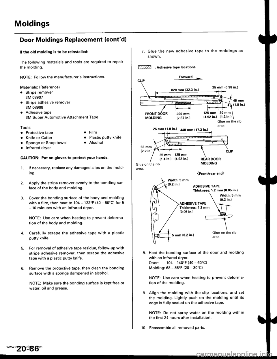
7. Glue the new adhesive tape
snown,
N : Adlesive tape locations
Forwerd L
820 mm 132.3 in.)
FRONTMOLDING
to the moldings as
25 mm {0.98 in.l
45 mm(1.8 in.l
200 mm(7.87 in.)
125 mm
{4.92 in.)30 mm
{1.2 in.}
t'.
Glue on the ribarea,26 mm (1.0 in.) 440 mm 117.3 in.l
35 mm 125 mm
{1.4 in.) {4.92 in.)REAR DOORMOLDING
(Front/rear end)
Width: 5 mm
Heat the bonding surface of the door and molding
with an infrared dryer.
Door: 104 - 140'F (40 - 60'C)
Molding: 68 - 86'F (20 - 30'C)
NOTE: Use care when heating to prevent deforma-
tion of the molding.
Align the molding with the clip locations, and set
the molding. Lightly push on the molding until its
edge is fully seated on the adhesive tape.
NOTE: Oo not spray water on the molding within
the first 24 hours after installation.
Reassemble all removed parts.10.
www.emanualpro.com
Page 1075 of 1395
Openers
Fuel Fill Door Opener Cable Replacement
NOTE:
. When removing the clips, use a clip remover.
. Take care not to bend the opener cable.
Remove the following parts, then pull the carpet back, as necessary (see page 20-45),
a
>: Clip locationsA>,6 B>, 1
a
a
FUEL FILL OOOR LATCH(see page 20-96)
Kick panel (left side. see page 20-41)
Center pillar lower trim panel (left side, see page 20-
41)
Front side trim (left side, see page 20-41)
Rear seat (left side, see page 20-63)
Cargo area floor and cargo storage bin (see page
43)
Rear trim panel {see page 20-42)
Rear side trim panel (left side, see page 20-421
Rear side trim (left side, see page 20-41)
FUEL FILL DOOR OPENER
{see page 20-96)
20-
c>,1
@lRlg
Installation is the reverse of the removal procedure.
NOTE:
. lf necessary, replace any damaged clips.
r Make sure fuel fill door opener cable is routed and connected properly.
. Make sure the fuel fill dooropens properly.
www.emanualpro.com
Page 1077 of 1395
Openers
Fuel Fill Door Opener Replacement
NOTE: Take care not to bend the opener cable.
Remove the left front side trim (see page 20-41).
>: Bolt locstions.2
5x1.0mm9.8 N.m (1.0 kgf.m,7.2 tbt.ftl
FUEL FILL DOOROPENER CABLE(see page 20-94)
Installation is the reverse of the removal procedure.
NOTE:
. Make sure the opener cable is connected properly.
. Make sure the fuel fill door opens properly,
20-96
Fuel Fill Door Latch Reolacement
NOTE: Take care not to bend the opener cable.
Remove the rear speaker cover and rear speaker from
the left rear side trim panel (see page 20-42).
>: Boh locdions, 2
6x1.0mm9.8 N.m (1.0 kgf.m,7.2 tbf.ft)FUEL FILL DOOR LATCH
FUEL FILL DOORAfter installing, check fora flush fit with the body.
CAELE(see Page
LATCH
DOOR OPENER
20,94)
FUEL
FUEL FILLRemove the fuel fill door latchby turning it 90'
Installation is the reverse of the removal procedure.
NOTE: Make sure the fuel fill door opens properly
and locks securely.
www.emanualpro.com
Page 1170 of 1395
Relay and Control Unit Locations
Dashboard (cont'd) and Door
REAR ACCESSORY SOCKET RELAYI Wire colors: YEL/GRN, JIWHT/BLK. BLK, .nd YEL/BLU l
REVERSE RELAY {A/TII Wire colonr YEI-/RED, IIYEL/RED, YEL, .nd GRN/BLK IREAR WINDOW WIPERCONTROL UNIT 137 mod.ll
KEYIISS/POWER DOOR L(rcKCONTROL UNIT
INTERLOCX CONTROL UNIT
23-10
www.emanualpro.com
Page 1171 of 1395

Gonnector ldentification and Wire Harness Routing
How to ldentity Connectors:
ldentification numbers have been assigned to all connectors, The number is preceded by the letter "C" for connectors.
"G" for ground terminals or "T" for non-ground terminals.
Location
HarnessEngine CompartmsntDashboardOthers lFloor, Door,
8oof, Tailgate)
Starter cableT1, T2 and @
Battery ground cableG1 and O
Engine ground cableT3
Transmission ground cableT4
G3
Engine wire harnessC101 through C137
T101 and T102
G101
Engine compartment ware harnessC201 through C218
G201 and G202
Under-hood ABS fuse/relay box
wire harness
t5ano9
Main wire harnessC301 through C309
C351 through C361
C401 through C447
G401 and G402
Dashboard wire harnessC501 through C524 (C525)
G501
Left side wire harnessC551 through C581
G551, G552 and G553
Right side wire harnessC601 through C605
lnterior wire harnessC701 through C703
Rear bumper wire harnessC641 through C643
Heater sub-harnessC731 through C740
Secondary heated oxygen sensor
sub-harness
C721 through C722
Combination switch sub-harnessC751 through C760
Driver's door wire harnessC661 through C667
Front passenger's door wire harnessC6Tl through C676
Left rear door wire harnessC681 through C684
Right rear door wire harnessC69'l through C694
Rear wire harnessC611 through C520
Tailgate wire harnessC631 through C634
G631
SRS main harnessC801 through C808
G801
High mount brake light sub-harnessC651 through C653
Fuel tank oressure sensor sub-harnessC645 through C647
www.emanualpro.com