1997 HONDA CR-V Unit 26p
[x] Cancel search: Unit 26pPage 957 of 1395

ABS Control Unit Terminal Arrangement
ABS CONTROL UNIT 26P CONNECTOR
Wire side of female terminals
TeiminalnumbelWiiecolorTerminal3ignTeiminalnamglDescription
Voltrge
tdminalsCondhions(lgnition Switch ON llll)Output voltago
1GRNn/VHTPCOM(Primary
common)
Power source for the solenoidvalve and pump motor.1-GNDON6
ONOV
OFFAC:3-6V
2BLI(WHTSCOM(Secondary
common)
Power source for the solenoid2-GNDOFF
lConnect the SCS seNice] connector IApprox.3 V
BLVBLU(lgnition 2)Detects ignition switch 2signal. (System activate signal)3-GNDBattery Voltage
4BLUA/ELRRO(Rear-right 0)Detocts right-rear wheelsensor srgnat.When the wheel isturned at 1 turn/second.
53 mV or above ondigitaltester (ACrange) {Beference)150 mvtrp or aboveon oscilloscope
GRYRLO(Rear-left 0)Detects left-rear wheel sensorsrgnat.6-19
8GRNFRO(Fronr-right 0)Detects right-front wheelsensor signal.8-21StopsApprox.2.5 VSTOP
{Stop)Detects bfake switch signal.(Prevents unnecessary ABS operation)9-GNDBrake pedal pressed.Battery Voltage
Brake Dedal released.OV
10BRN^/VHTFLO(Front-left 0)
Detects left-front wheel sensorsrgnal.
10-23
When the wheel isturned at 1 turn/second.
53 mV or above ondigitaltester lACrange) (Reference)
150 mvpp or aboveon oscilloscope
StopsADprox. 2.5 V
YELRL-oUT(Rearleft outlet)
Drives left-rear outlet solenoid12.GNDONONOV
OFFAC:3-6V
13RED^/vHTRR.IN(Rear-right
inlet)
Drives right-rear inlet solenoid13.GNDOFF
lConnect the SCS service\ connector IApprox. 3 V
14WHT/GRNB1(Baftery 1)Power source for the solenoidvalve and pump motor.14.GND
Every timeBattery Voltage82(Battery 2)Power source for the solenoidvalve and pump motor.15-GND
16BLKGND2(Ground 2)Ground for the ABS controlunit.16-GNDBelow 0.3 V
't7GRN/YELRR1(Rear-right 1)Detects right-rear wheelsensor signal.'t7 -4
When the wheel is turnedat l turn/second,
53 mV or aboveon digitaltester(AC range)(Reference) 150mVp-p or aboveon oscilloscope
19LT BLURL1(Rearieft 1)Detects left-rear wheel sensorsignal.19-6
GRN/BLKFR1(Front-right 1)Detects right-front wheelsensor srgnat.21-8
23GBN/ORNFL1{Front-left 1}Detects left-front wheel sensorsagnal.23-10StopsApprox. 2.5 V
REDRLI N(Rear-left inlet)
Drives left-rear inlet solenoid
25,GND
ON
=
-9ONOV
AC:3-6V
OFF
/Connect the SCS service] conneclor IApprox. 3 V
26BLKGND3(Gtound 3)Ground tor the ABS controluntI.26-GNDBelow 0.3 V
19-34
www.emanualpro.com
Page 966 of 1395

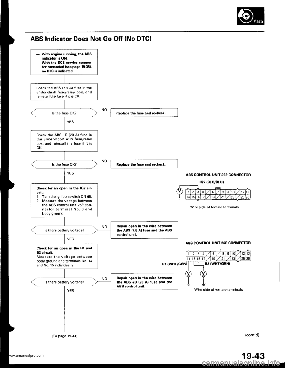
- With engine running, the ABSindicsior is ON.- With the SCS service connec-tor conn€cted (s€€ page 19381,no DTC is indicated.
Check the ABS {7.5 A) fuse in theundeFdash fuse/relay box, andreinstall the fuse if it is OK.
ReDlace lhe tuse and recheck.
Check the ABS +B (20 A) fuse inthe underhood ABS fuse/relaybox, and reinstall the fuse if it isoK.
Replace the fuse and rocheck.
Check for sn open in the lG2 cir-cuit:1. Turn the ignition switch ON {ll).2. Measure the voltage betweenthe ABS control unit 26P con-nector terminal No. 3 andbody ground.
Repair open in tho wire betweenthe ABS {7.5 A} fu3e .nd the ABScontrol unit,
Check for an open in the 81 and82 circuit:Measure the voltage betweenbody ground and terminals No. 14and No. 15 individually.
Ropair open in tho wi.e betweenrhe ABS +B {20 A) fuse and theABS control unit.is there battery voltage?
ABS Indicator Does Not Go Off (No DTGI
A8S CONTROL UNIT 26P CONNECTOR
IG2IBLK/BLU)
Wire side of female terminals
ABS CONTROL U N 26P CONf{ECTOR
{WHT/GRNI
(cont'd)
Wire side of female terminals
(To page 19 44)
19-43
www.emanualpro.com
Page 967 of 1395

Troubleshooting
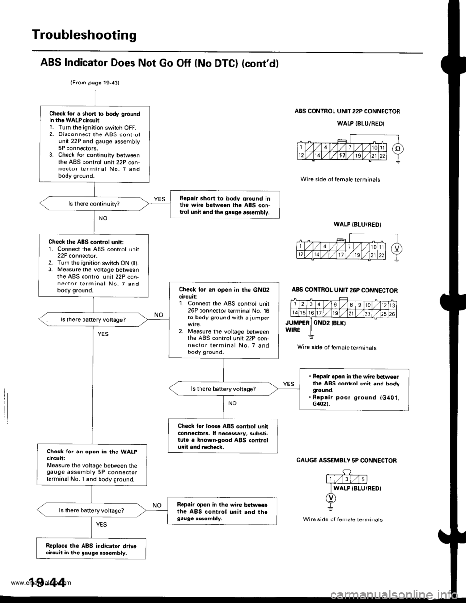
ABS Indicator Does Not Go Off (No DTC) (cont'dl
ABS CONTROL UNIT 22P CONNECTOR
WALP {BLU/REDI
Wire side of female terminals
JUMPCRWIREGND2IBLKI
GAUGE ASSEMBLY 5P CONNECTOF
(From page 19,43)
Check tor a short to body groundin the WALP circuil:1. Turn the ignition switch OFF.2. Disconnect the ABS controlunit 22P and gauge assembly5P connectors.3. Check lor continuity betweenthe ABS control unit 22P con-nector terminal No. 7 andbody ground.
Repair short to body ground inthe wire between the ABS con-t.ol unh and the gauge assembly.
Check the ABS control unit:1. Connect the ABS control unit22P connector.2. Turn the ignition switch ON (ll).3. Measure the voltage betweenthe ABS control unit 22P con-nector terminal No. 7 andbody ground.Check tor an open in the GND2circuit:1. Connect the ABS control unit26P connecto. terminal No. 16to body ground with a jumper
2. Measure the voltage betweenthe ABS control unit 22P con-nector terminal No. 7 andbody ground.
ls there battery voltage?
. Repeir op6n in th6 wire ttetweenthe ABS control unit and bodyground.. Rep.ir poor ground {G401,G4021.
Check lor loose ABS control unhconnectors. lf necesssry, substi-tuie e lnown-good ABS controlunit and recheck.Check tor an open in the WALPcircuit:Measure the voltage between thegauge assembly 5P connectorterminal No. 1 and body ground.
Repair op6n in the wi.e botw€enthe ABS control unit and th€gau9e ass€mbly.
ls there battery voltage?
Replaco the ABS indicator drivecircuit in the gauge assembly.
ABS CONTROL UNIT 26P CONNECTOR
Wire sade of female terminals
WALP IBLU/FEDI
19-44
www.emanualpro.com
Page 968 of 1395

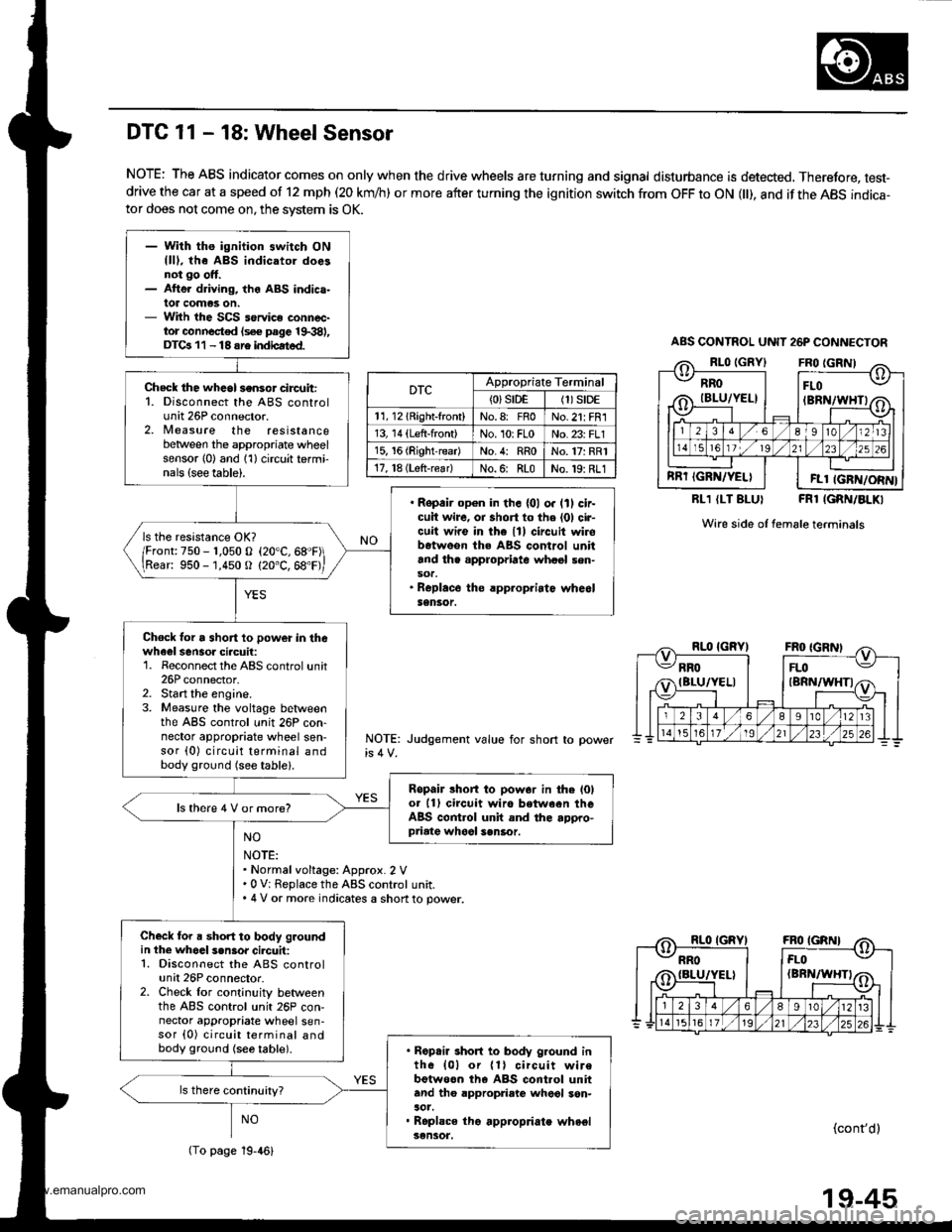
- With ths ignition switch ONllll, the ABS indicatol doesnot go ott.- Atte. driving, the ABS indica-lot comas on.- With the SCS service connec-tor connocted (s€€ page 19.381,DTGr 11 - 18 sre indbated.
Check the whcol sensor circuit:1. Disconnect the ABS controlunit 26P connector.2, Nleasure the resistancebetween the appropriate wheelsensor l0) and 1'l) circuit termi-nals {see table).
. Ropair op€n in th. {01 o. lll cir-cuit wire, oa short to the (01 cir-cuit wire in the lll circuit wirobetweon the ABS control unitand th. appropriate whasl sen-sot.. Roplace the rpp.opriatc whe6lSensor.
ls the resistance OK?
/Fronr:750 - r,050 o (20"C,68"F\
\Rear: 950 -'1,450 O (20"C, 68'F,
Chock lor a short 10 power in thewheel sensoa ciacuil:1. Reconnect the ABS control unit26P connector.2. Start the engine.3. Measure the voltage betlveenthe ABS control unit 26P con-nector appropriate wheel sen-sor (0) circuit terminal andbody ground (see table).
Ropair lhort to pow.r in the l0lot 11) circuit wiro between theABS control unit and the appro-priate whool sen6or.
ls there 4 V or more?
Check for a short to body groundin the whoal s.n3or cilcuit:1. Disconnect the ABS controlunit 26P connector.2. Check lor cont;nuity betweenthe ABS control unit 26P con-nector appropriate wheel sen-sor {0) circuit terminal andbody ground {se6 table).. Ropair short to body g.ound inth6 {01 or {1} circuit wirebotweon th6 ABS cont.ol unitand tho appropriato wheol son-aot.. Roplace tho appropriate wheelsensot.
DTC 11 - 18: Wheel Sensor
NOTE: The ABS indicator comes on only when the drive wheels are turning and signal disturbance is detected, Therefore, test-drive the car at a speed of 12 mph (20 km/h) or more after turning the ignition switch from OFF to ON l), and if the ABS indica-tor does not come on, the svstem is OK.
RLl (LT BLUI FRl IGRN/BLKI
Wire side of female terminals
NOTE: Judgement value for short
NO
NOTE:. Normalvoltage: Approx. 2 V.0 V: Replace the ABS control unit.. 4 V or more indicates a shon to power.
NO(cont'dl
ABS CONTNOL UNIT 26P CONNECTOR
RROIBLU/YEL}
RRT IGRN/YELI
FLO(BRN/WHTI
FLl IGFN/ORN}
DTCAppropriate Terminal
{0}srDE(1)S|DE
11, l2lRight-front)No.8: FnoNo.21: FR1
13, 14 (Left-front)No. 10rFLoNo. 23: FLl
15, 16 (RightreadNo.4: RRoNo.17: RR1
17, l8 (Lsft-rear)No.6: RLoNo.19: RL1
(To page 19-46)
19-45
www.emanualpro.com
Page 970 of 1395

DTC 31 - 38: Solenoid
ABS CONTROL UNIT 22P CONNECTOR
Wire sade of female terminals
Wire side of female terminals
ABS CONTROL UNIT 26P CONNECTOR
FL.OUT IYEL/8LKI
DTCAppropraateConnectorTerminal
31: FR'lN22PNo. 1
32: FR OUT22PNo. 12
33: FL lN22PNo. 11
34: FL OUT22PNo.10
35:RR-lN26PNo.13
36: RR-OUT22PNo.21
37: RLIN26PNo.25
38: RL-OUT26PNo. 12
RL.OUT {YELI
FL.OUT IYEL/BLKI
DTCAppropriateTerminal
31: FR lNNo. 2i SCOM
32: FR-OUTNo. 2: SCOM
33: FLINNo.1:PCOM
34: FL-OUTNo. 1:PCOM
35:RRINNo. 1: PCON4
36: RR-OUTNo. 1: PCON4
37rRL-lNNo. 2: SCOM
3a: RL-OUTNo. 2: SCOM
RL.OUT {YELI
- With the ignition switch ON{lD, tho ABS indicator doesnot go off, or the ABS indic.-lor comes on whil6 ABS istunctioning.- With th€ SCS service connoc-tor connoctcd {sce page 1$381,DTCa 31 - 38 ars indicatsd.
Check for a 3hori to power in th€solenoid ci.cuit:1. Disconnect the ABS controluntr tlr ano zbr connectors_2. Start the engine.3. Measure the voltage betweenthe appropriate ABS controlunit connector solenoid circuitterminal and body ground (see
table).
R€pair short to power in theapprop.iato solenoid circuit wirebetwe€n the ABS control unitand the modulator unh.
ls there baRery voltage?
Chock for a short to body groundin the sol€noid circuit:Check for continuity between theappropriate solenoid circuit termi-naland body ground (see table).
. Ropair short to body ground inthe appropriato solenoid circuitwire betwoon the ABS controlunit and the modulator unit.. Replace the modulator unit.
ls there continuity?
Check the ABS control unit:1. Turn the ignition switch OFF.2. Connect the ABS control unit22P and 26P connectors.3. Connect the SCS service con-nector.4. Turn the ignition switch ON (ll).5, Measure the voltage betweenthe appropriate ABS controlunit 26P connector COM circuitterminal and body ground (seetable).
Check tor loose ABS control unitconnectors. ll nece$ary, substi-tut€ a known-good ABS controlunit and recheck.
ls there approx. 3 V7
PCOM
(To page l9-48){GRN/WHTI
19-47
www.emanualpro.com
Page 971 of 1395

Troubleshooting
DTC 31 - 38: Solenoid (cont'dl
A8S CONTROL UNIT 22P CONNECTOR
Wire side of female terminals
ABS CONTROL UNIT 26P CONNECTOR
Check for an open in the solenoidcircuit:Measure the voltage between theappropriate ABS control unit connector solenoid circuit terminaland body ground {seetable).. Repair open in the appropriateCOM circuit wire botween theABS control unit and th€ modu-lator unit.. Repair open in the appropriatesolenoid circuit wire betw€onlhe ABS control unit and themodulator unit.. Replace ih€ modulator unit.
ls there approx. 3 V?
Check for loos€ ABS control unilconn€ctors. lf nece$ary, substi-tute a known-good ABS controlunit and rechock.
FL.OUT IYEL/BLK}DTCConnector
31: FRIN22PNo. 1
32: FR-OUT22PNo.12
33: FL-IN22PNo.11
34: FL OUT22PNo.10
35:RRIN26PNo.13
36:RR-OUT22PNo.21
37:RLIN26PNo. 25
38:RL-OUTNo. 12
RI-.OUT {YEL)
Wire side of female termanals
19-48
www.emanualpro.com
Page 975 of 1395
![HONDA CR-V 1997 RD1-RD3 / 1.G Workshop Manual
Troubleshooting
DTG 54: Main Relay
IWHT/GRNI
AAS CONTROL UNIT 26P CONNECTON
Wire side of female terminals
ABS COf{TROL UN]T 22P CONNECTOR
PCOMIGRN/WHTIscoM{BLK/WHTI
Wire side of female terminals
- Wi HONDA CR-V 1997 RD1-RD3 / 1.G Workshop Manual
Troubleshooting
DTG 54: Main Relay
IWHT/GRNI
AAS CONTROL UNIT 26P CONNECTON
Wire side of female terminals
ABS COf{TROL UN]T 22P CONNECTOR
PCOMIGRN/WHTIscoM{BLK/WHTI
Wire side of female terminals
- Wi](/manual-img/13/5778/w960_5778-974.png)
Troubleshooting
DTG 54: Main Relay
IWHT/GRNI
AAS CONTROL UNIT 26P CONNECTON
Wire side of female terminals
ABS COf{TROL UN]T 22P CONNECTOR
PCOMIGRN/WHTIscoM{BLK/WHTI
Wire side of female terminals
- With the ignition switch ON(lll, the ABS indicator doesnot go off.- With the SCS service connec-tor connected {see page 19-381,DTC 54 is indicatod.
Check the ABS +B 120 A) fuse inthe under-hood ABS luse/relaybox, and reinstall the fuse if it isoK.
FeDlace the tu3e and recheck.
Ch€ck tor an open in the 81, 82circuit:Measure the voltage betweenbody ground and the ABS controlunit 26P connector terminal No. 14and No. 15 individually.
Repair open in the wiro bstweonth6 ABS conirol unit and theunder-hood ABS fuse/rolay box,
ls there battery voltage?
Check for a short to body groundin the PMR circuit:L Turn the ignition switch OFF.2. Remove the pump motor relay.3. Disconnect the ABS controlunit 22P connector.4. Check lor continuity betweenterminal No. 19 and bodygrouno.
Repair short to body ground inthe wire betweon the under-hood ABS lGe/r.lay box and theABS control unit.
Check for a short to body groundin the PCOM, SCOM cilcuit:1. Disconnect the ABS controlunit 26P connector.2. Check tor continuity betweenbody ground and the ABS con-trol unit 26P terminals No- 1and No.2 individually.
. R€pair short to body ground inth€ P1COM circuit wire betweenthe ABS control unit and theund6r-hood ABS tuse/r6layoox.. R6p.ir short to body ground inthe PCOM or SCOM circuit wirebetweon th6 ABS control unitand lhe mod!lator unit.. R.Dlece tho modulrtor unit.(Short circuit inside the unitl
ls there continuity?
(To page 19-53)
www.emanualpro.com
Page 976 of 1395

Check fo. a short to power in thaPCOM, SCOM circuhi1. Start the engine.2. Measure the voltage betweenbody ground and ABS controlunit 26P connector terminalsNo. I and No.2 individually.
'Repair short to powor in thsFCOM circuit wiro botwoon th€ABS control unit and the under-hood ABS tuse/r.lay box.. Repeir 3hort to power in thoPCOM or SCOM circuit wirebetwegn tho ABS control uniiand ths modulator unh,. R.placo tha modulatoi unit.(Shon to power in.ido th6 unitl
ls there 8 V or more?
Tu.n tho ignhion switch OFF andconnect thc SCS 3orvice connec-tor. Then turn thc ignition switchON (lll and measure tha voltagobotween the PCOM .nd SCOMtsrminal3 and body gJound. Itther6 is 0 V, .epleco tho ABS con-trol unit.
ABS CONTROL UNIT 26P CONNECTOR
PCOM
Wire side of temale terminals
NOTE: 8 V or more indicates a short to
(GRN/WHTI SCOM
www.emanualpro.com