1997 HONDA CR-V positive terminal
[x] Cancel search: positive terminalPage 779 of 1395

26. Connect the vehicle speed sensor (VSS). the coun-
tershaft speed sensor. and the A,/T gear position
switch connectors,
VEHICLE SPEEO
SPEED SENSOACO'{NECTOR
Connect the lock-up control solenoid valve connec-
tor, then install the harness clamp on the clamp
bracket.
HARNESS CI-AMP
27.
RADIATOR HOSECLAMP
TRANSMISSIONGROUND CAB1ITERMINAL
LOCK-UP OONTROLSOLENOID VALVECONNECTOR
6x1.0mm12 N'm (1.2 kgi.m,8.? tbtftl
28.
29.
Instail the transmission ground cable terminal on
the transmission hanger, and install the radiator
hose clamp on the transmission hanger,
Connect the starter cables to the starter, and install
the harness clamD on the clamD bracket. Make sure
the crimped side of the starter cable ring terminal is
facing out.
STARTEBCABLE
STARTER CAAtf,
Install the air cleaner housing assembly and the
intake air duct.
Refill the transmission with ATF (see page 14-161).
Connect the battery positive terminal and negative
terminal.
Set the parking brake, Start the engine, and shift the
transmission through all gears three times.
Check the shift cable adjustment (see page 14-271]-.
Check the tront wheel alignment and adjust it if
needed (see section 18).
Let the engine reach normal operating temperature
(the radiator fan comes on) with the transmission in
E or N position, then turn it off and check the ATF
level {see page 14-160).
Perform a road test (see page 14-157 and 14-158).
30.
31.
34.
CLAMP BRACKET
37.
14-263
www.emanualpro.com
Page 932 of 1395
![HONDA CR-V 1997 RD1-RD3 / 1.G Workshop Manual
Inspection and Adjustment
Brake System Indicator
Circuit Diagram lNuLR.HorJDGNrT 0llSt!ITCHUNDEB.DASHFUSE]NEtAY BOIrllA Nl] 42 4!A
PAF�K NC BRA(E S\IICH
GBNiBEO
Io\lt j I ERAKE tuU 0 rEVEr 9!1 I(N
| HONDA CR-V 1997 RD1-RD3 / 1.G Workshop Manual
Inspection and Adjustment
Brake System Indicator
Circuit Diagram lNuLR.HorJDGNrT 0llSt!ITCHUNDEB.DASHFUSE]NEtAY BOIrllA Nl] 42 4!A
PAF�K NC BRA(E S\IICH
GBNiBEO
Io\lt j I ERAKE tuU 0 rEVEr 9!1 I(N
|](/manual-img/13/5778/w960_5778-931.png)
Inspection and Adjustment
Brake System Indicator
Circuit Diagram lNuLR.HorJDGNrT 0llSt!ITCHUNDEB.DASHFUSE]NEtAY BOIrllA Nl] 42 4!A
PAF�K NC BRA(E S\I'ICH
GBNiBEO
Io\lt j I ERAKE tuU 0 rEVEr 9!1 I(N
| oPt^r'f,'1 .r
BIKI-o-:G401
Parking Brake Switch Test
1. Remove the parking brake cover,
2. Disconnect the connector from the parking brakeswitch.
3. Check for continuity between the terminal and bodyground in each position according to the table.
Terminal
Lever Position \
Positive
TerminalBody Ground
Lever Up--o
Lever Down
NOTE (Canada): lf the parking brake switch is OK, butthe brake system indicator does not function, perform
the input test for the daytime running lights control unit(see section 23).
Brake Fluid Level Switch Test
1. Remove the reservoir cap. Check that the float
moves up and down freely; if it doesn't, replace the
reservoir cap assembly.
2. Check for continuity between the terminals in each
switch position according to the table.
- r9''r
Position12
FLOAT UP
FLOAT DOWNo
RESERVOIR CAP
GROUND
Switch contacts open atproper fluid level.
19-8
www.emanualpro.com
Page 1172 of 1395
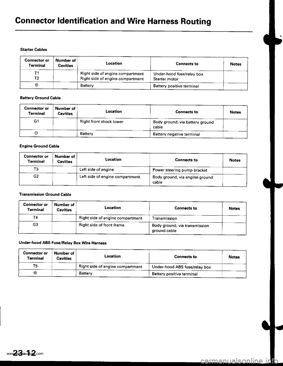
Connector ldentification and Wire Harness Routing
Connoctor or
Terminal
Number of
CavitiesLocationConnects toNotes
T1
r2
Right side of engine compartment
Right side of engine compartment
Under-hood fuse/relay box
Starter motor
oBatteryBattery positive terminal
Starter Cables
Battery Ground Cable
Connoctor or
Terminal
Number of
CavitiesLocationConneqts loNotes
GIRight front shock towerBody ground, via battery ground
cable
BatteryBattery negative terminal
Engine Ground Cable
Connector or
Terminal
Numb6r ol
CavitiesLocationConnects toNotes
T3Left side of enginePower steering pump bracket
Left side of engine compartmentBody ground. via engine ground
caote
Transmission Ground Cable
Connsstor o.
Terminal
Number of
CavitiesLocationConnects toNotes
T4Right side of engine compartmentTransmission
Right side of front frameBody ground, via transmissionground cable
Under-hood ABS Fuse/Relay Box Wire Harnsss
Conn6stor or
Terminal
Number of
CavitiesLocationConnocts toNotos
tcRight side of engine compartmentUnder-hood ABS tuse/relav box
@Battery88ttery positive terminal
23-12
www.emanualpro.com
Page 1266 of 1395
Horns
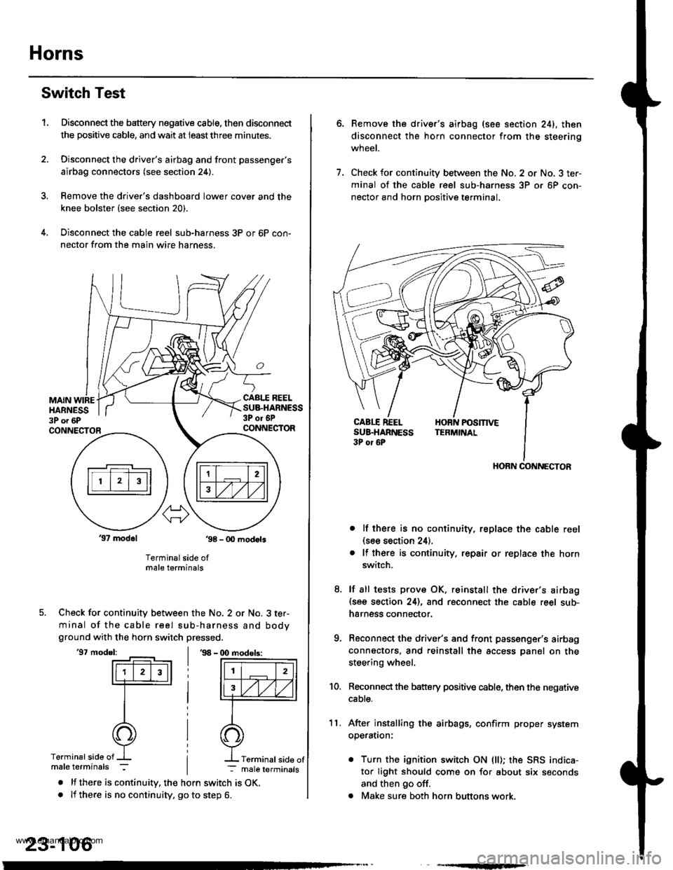
Switch Test
Disconnect the battery negative cable, then disconnect
the positive cable, and wait at ieastthree minutes.
Disconnect the driver's airbag and front passenger's
airbag connectors (see section 24).
Remove the drive.'s dashboard lower cover and the
knee bolster (see section 20).
Disconnect the cable reel sub-harness 3P or 6P con-
nector from the main wire harness.
1.
MAIN WIREHARNESS3P o. 6P
CABI.I REELSUB.HARNESS3P or 6PCONNECTORCONNECTOR
37 modol ,98 - 0O modots
Terminal side ofmale terminals
Check for continuity between the No. 2 or No. 3 ter-
minal of the cable reel sub-harness and bodyground with the horn switch pressed.
'97 model:'98 - (X) modols:
Terminalside of
. lf there is continuity. the horn switch is OK.. lf there is no continuity, go to step 6.
23-106
Terminal side of
6.Remove the driver's airbag (see section 241, then
disconnect the horn connector from the steerinq
wneet.
Check for continuity between the No. 2 or No. 3 ter-
minal of the cable reel sub-harness 3P or 6P con-
nector and horn Dositive terminal.
lf there is no continuity, replace the cable reel(see section 24).
lf there is continuity. repair or replace the horn
switch.
lf sll tests prove OK, reinstall the driver's airbag(see section 24), and reconnect the cable reel sub-
harness connector.
Reconnect the driver's and front passenger's airbag
connectors, and reinstall the access panel on the
steering wheel.
Reconnect the battery positive cable, then the negative
cable.
After installing the airbags, confirm proper system
operatron:
. Turn the ignition switch ON (ll); the SRS indica-
tor light should come on for about six seconds
and then go off.
. Make sure both horn buttons work.
7.
11.
8.
9.
10.
HORN CONNECTOR
www.emanualpro.com
Page 1272 of 1395
Rear Window Defogger
Function Test
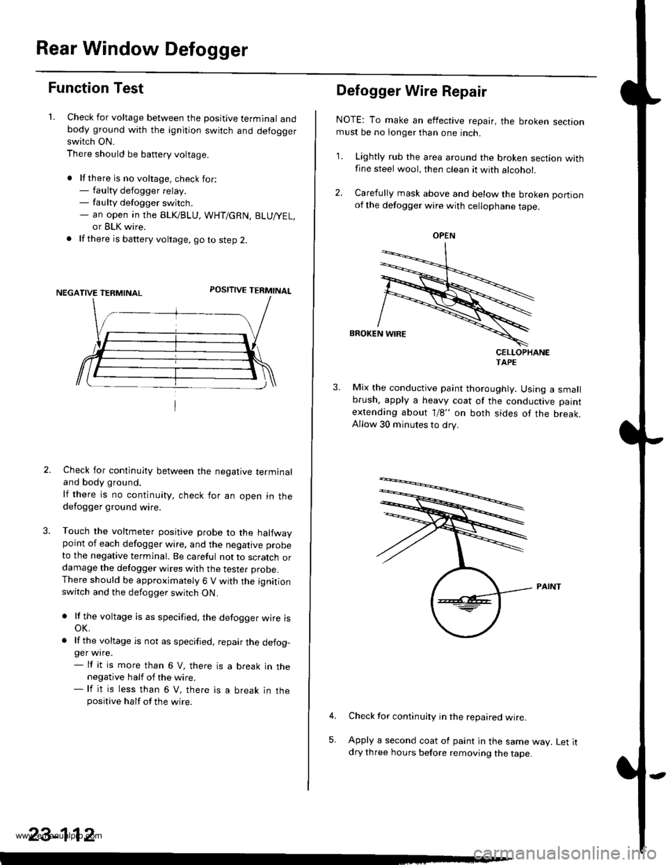
1. Check for voltage between the positive terminal andbody ground with the ignition switch and defoggerswitch ON.
There should be battery voltage.
. lf there is no voltage. check for:- faulty defogger relay.- faulty defogger switch.- an open ,n the BLK/BLU, WHT/GRN, BLU/YEL,
or BLK wire.
. lf there is battery voltage, go to step 2.
POSITIVE TERMINAL
Check for continuity between the negative terminaland body ground.
lf there is no continuity, check for an open in thedefogger ground wire.
Touch the voltmeter positive probe to the halfwaypoint of each defogger wire, and the negative probe
to the negative terminal. Be careful not to scratch ordamage the defogger wires with the tester probe.There should be approximately 6 V with the ignitionswitch and the defogger switch ON.
. lf the voltage is as specified, the defogger wire isoK.
. lf the voltage is not as specified, repair the defog-ger wire.- lf it is more than 6 V, there is a break in thenegative half of the wire.- lf it is less than 6 V, there is a break in thepositive half of the wire.
23-112
Defogger Wire Repair
NOTE: To make an effective repair, the broken sectionmust be no longer than one inch.
1. Lightly rub the area around the broken section withfine steel wool, then clean it with alcohol.
2. Carefully mask above and below the broken portionof the defogger wire with cellophane tape.
CELLOPHANETAPE
Mix the conductive paint thoroughly. Using a smallbrush, apply a heavy coat of the conductive paint
extending about 1/8" on both sides of the break.Allow 30 minutes to dry.
Check for continuity in the repaired wire.
Apply a second coat of paint in the same way. Let itdry three hours before removing the tape.
5,
OPEN
www.emanualpro.com
Page 1333 of 1395
Troubleshooting
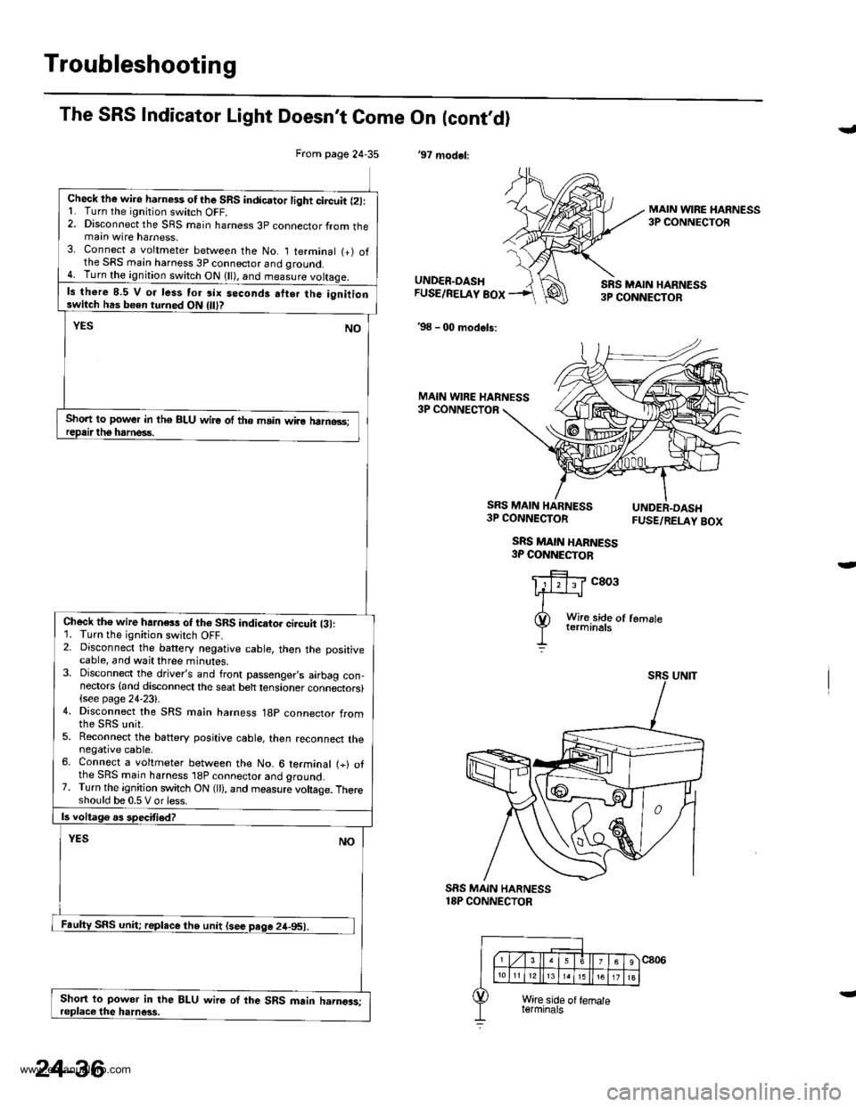
From page 24-35
Check lhe wire harness otthe SRS indicator light circuit l2l:L Turn the ignitjon switch OFF.2. Disconnect the SRS main harness 3p connector from themain wire harness.3. Connect a voltmeter between the No. I terminal (+) ofthe SRS main harness 3P connector and qround.4. Turn the ignition switch ON (ll), and measure voltaqe.
ls there 8.5 V o. less tor six seconds atter the ignitionswitch has been turned ON
Short to power in th€ BLU wire of the main wiro halno3s;
Check th€ wire hahess of th6 SRS indicator ci.cuit {31:1. Turn the ignition switch OFF.2. Disconnect the battery negative cable, then the positivecable, and wait three minutes.3. Disconnect the driver's and front passenger,s airbag con-nectors {and disconnect the seat belt tensioner connectors}(see page 24-23).4. Disconnect the SRS main harness 18p connector from
5. Reconnect the battery positive cable, then reconnect thenegative cable.6. Connect a voltmeter between the No. 6 terminal (+) ofthe SRS main harness 'l8P connector and ground.7. Turn the ignition switch ON (ll), and measure voltage. Thereshould be 0.5 V or less.
Short to power in the BLU wire oI the SRS main harngas;
The SRS Indicator Light Doesn't Come On (cont,dl
'97 modol:
J
MAIN WIRE HARNESS3P CONNECTOR
UNDER.DASHFUSE/RELAY BOX
'98 - 00 models:
SRS MAIN HARN€SS3P CONNECTOR
MAIN WIRE HARNESS3P CONNECTOR
SRS MAIN HARNESS3P CONNECTOR
SRS MAIN HARNESS3P COI{NECTOB
FUSE/RELAY BOX
c803
SRS MAIN HARNESS18P CONNECTOR
24-36
www.emanualpro.com
Page 1334 of 1395
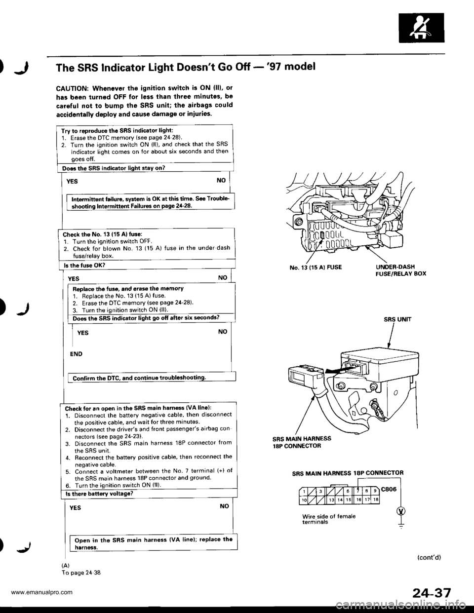
The SRS Indicator Light Doesn't Go Off -'97 model
CAUTION: Whenever th€ ignilion switch i3 ON (lll, ol
has been turn€d OFF for less than three minutes, be
careful not to bump the SRS unit; the airbags could
accidenially deploy and cause damag€ or iniuries.
Try to reproduce the sRs indicator light:
1. Erasethe DTC memory (see page 24 28)
2. Turn the ignition switch ON {ll), and check that the SRS
indicator light comes on for about six seconds and thengoes off.
Doe3 the SRS indicator light slay on?
YESNO
Intermiftent ftilure, system is OK at this time. S€o Troubl€_
shooting Intermittent Failutes on p.ge 24_28.
Check the No. 13 (15 Al fuse:'L Turn the ignition switch OFF.
2. Check for blown No. 13 (15 A) fuse in the under dash
fuse/relay box.
ls lhe tuse OK?
YESNO
Replace the luse, and err3e the memory'1. Replace the No. 13(15A)fuse2. Erase the DTc memory (see page 24-28).
3. Turn the ignition switch ON (ll).
ioes the SRS indicatol light go off after 3ix s6conds?
YESNO
ENO
Confirm tho OTC, and continue ttouble3hooting.
Check for an open in the SRS main hatn€ss {VA lins}:
1. Disconnect the batterY negative cable, then disconnect
the positive cable, and wait for three minutes.
2. Disconnect the driver's and front passenger's airbag con
nectors (see page 24-23).
3. Disconnect the SRS main harness 18P connector from
the sRs unit.4. Reconnect the battery positive cable, then reconnect the
negative cable.5. Connect a voltmeter between the No. 7 terminal (+) ot
the SRS main harness l8P connector and 9rouncl6. Turn the ignilion switch ON {ll).
ls there battory voltage?
YESNO
Ooen in the SRS main harness {VA line); replace the
natnoss.
(A)
No. 13 115 Al FUSEUNOER.DASHFUSE/RELAY BOX
)
SRS MAIN HARNESSr8P CONNECTOR
SRS MAIN HARNESS 18P CONNECTOR
(cont'd)
24-37
SRS UNIT
To page 24 38
www.emanualpro.com
Page 1339 of 1395
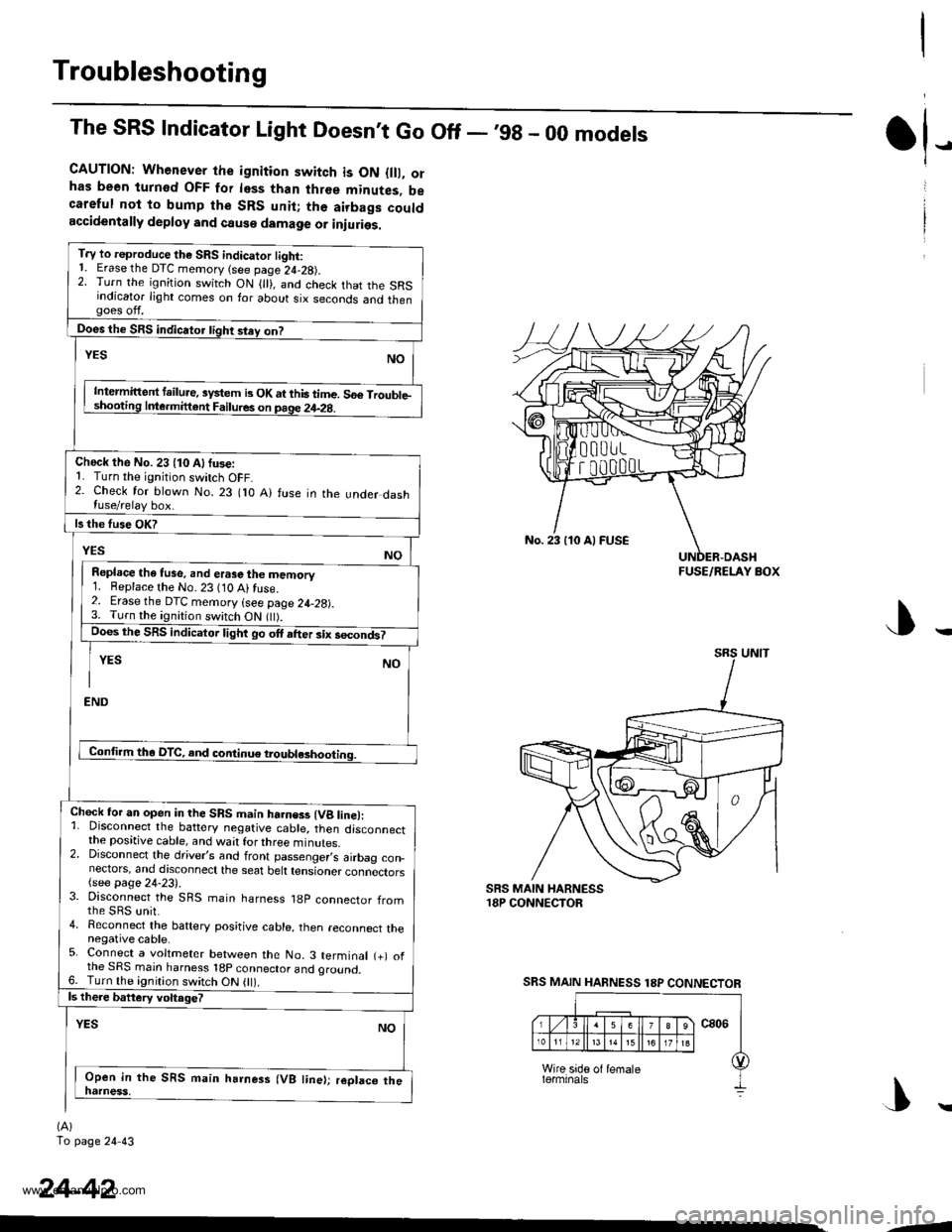
Troubleshooting
The SRS Indicator Light Doesnt Go Off - ,99 - 00 models
CAUTION: Whenever the ignition switch is ON {lll, orhas been turnod OFF for less than three minutes, becareful not to bump the SRS unit; the airbags couldaccidentally deploy and cause damage or iniuries.
T.y to reproduce the SRS indicator tight:1. Erase the DTC memory (see page 24-28).2. Turn the ignition switch ON { }, and check that the SRSindicator light comes on for about six seconds and thengoes off.
Does the SRS indicator tight stey on?
NOYES
Intermittent failure, system b OK at this time. 56€ Trouble-shooting Inle.mittent Failures on page 24-2g.
Check the No. 23 (10 Alfuse:1. Turn the ignition switch OFF.2. Check for blown No. 23 flO A) fuse in the under dashluse/relay box.
ls the fuse OK?
YESNO
Repl.ce the tuse, and erase the memory1. Beplace the No. 23 (10 Ai fuse.2. Erase the DTC memory (see page 24-28).3. Turn the ignition switch ON flt).Does the SRS indicator light go ott after six secondt
YES NO
I
END
Conti.m tha DTC, and continue troubl*hooting.
Chock for an open in the SRS main harness (Vg line):1. Disconnect the battery negative cable, then disconnectthe positive cable, and wait for three minutes.2. Disconnect the driver,s and front passenger,s airbag con_nectors, and discoonect the seat belt tensioner connectors(see page 24-23).3. Disconnect the SRS main harness 18p connector fromthe sRs unit.4. Reconnect the baftery positive cable, then reconnect thenegative cable.5. Connect a voltmeter between the No. 3 terminal (+) ofthe SRS main harness 18p connector and oround.6. Turn the ignition switch ON 0l).ls there battery voltage?
YESNO
Open in the SRS main harness (VB line); replaco thenatness,
(A)
To page 24 43
tl-
24-42
No. 23 110 Al FUSE
FUSE/RELAY BOX
SRS MAIN HARNESS 18P CONNECTOR
|\
-1
www.emanualpro.com