1997 HONDA CR-V positive terminal
[x] Cancel search: positive terminalPage 607 of 1395
![HONDA CR-V 1997 RD1-RD3 / 1.G Workshop Manual
Troubleshooting Flowchart - Interlock system - Key Interlock system
IGNITION SW]TCH 6P CONNECTOR
KEY LOCK SOL
{WHT/BLU)
ACC PUSH SW (WHT/YELI
Wire side oI female terminals
KEY LOCK SOL(WHT/BLUI
(cont HONDA CR-V 1997 RD1-RD3 / 1.G Workshop Manual
Troubleshooting Flowchart - Interlock system - Key Interlock system
IGNITION SW]TCH 6P CONNECTOR
KEY LOCK SOL
{WHT/BLU)
ACC PUSH SW (WHT/YELI
Wire side oI female terminals
KEY LOCK SOL(WHT/BLUI
(cont](/manual-img/13/5778/w960_5778-606.png)
Troubleshooting Flowchart - Interlock system - Key Interlock system
IGNITION SW]TCH 6P CONNECTOR
KEY LOCK SOL
{WHT/BLU)
ACC PUSH SW (WHT/YELI
Wire side oI female terminals
KEY LOCK SOL(WHT/BLUI
(cont'd)
lgnition key cannot be moved
Irom ACC (l) pGition to LOCK (0)
position while Pushing the igni-
tion kev with the shift lever in lllposifio;, and the shift lever but-
ton rcleased.
Check Key Interlock Solenoid
Op€ration:1. Disconnect the ignition switch
connector (6P).
2. Connect the No. 4 terminal of
the ignition switch 6P connec-
tor to the battery Positive ter
minal, and connect the No. 3
terminal to the battery nega
tive terminal.3. Check the key interlock sole
noid operation A clicking
so!nd sho!ld be heard.
Faulty koy interlock solenoid.
Replace the ignition key cylinder/
steedng lock as36mbly
Does the key interlock
solenoid operate properly?
Check Key Interlock Switch OPer'
adon:1. Connect the No. 5 terminal of
the ignition switch connector
to the battery Positive termi
nal, and connect the No 3 ter
minal to the baftery negative
termrnal,2. Turn the ignition switch to
ACC (l), then push rt.
3. Check the key interlock sole'
noid operation. A clicking
sound should be heard whilepushing the ignition key.
Faulty key inte.lock switch
Replaco the ignition key cylindor/
stoering lock a3r.mblY.
Does the key interlocksolenoid operate ProPerlY?
To page 14 92
14-91
www.emanualpro.com
Page 644 of 1395
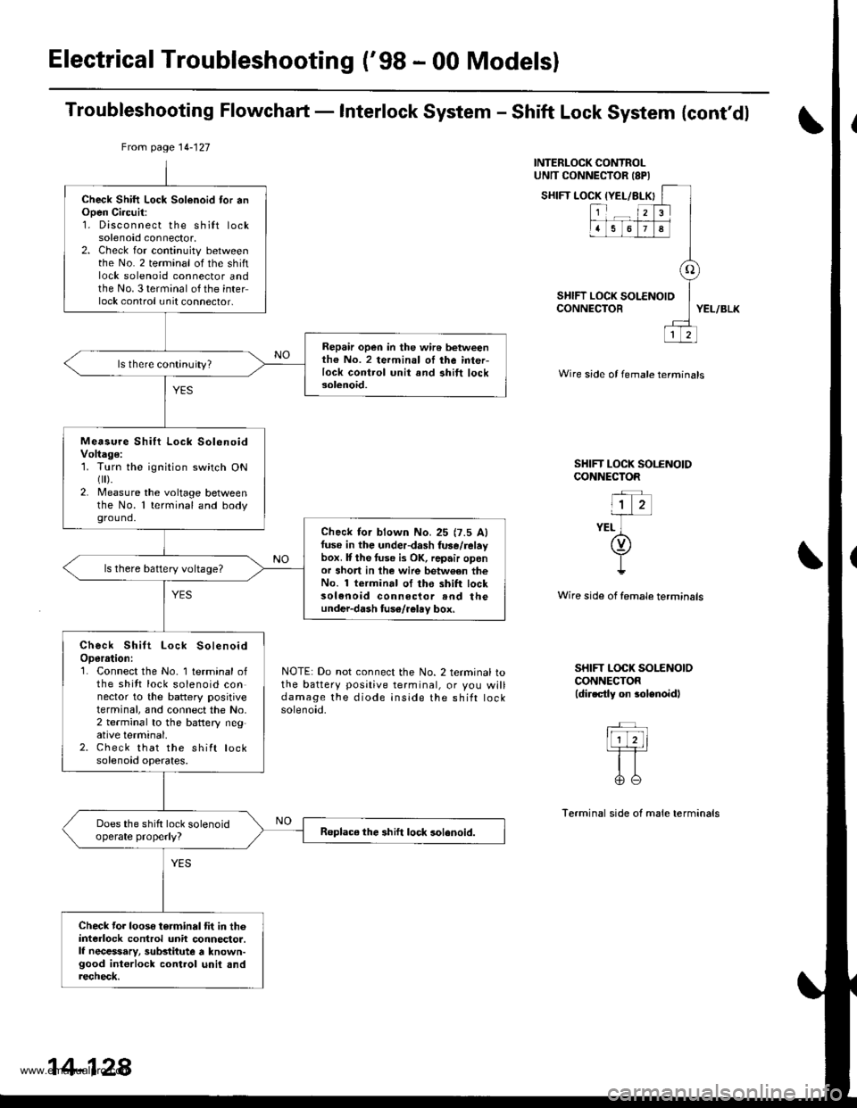
Electrical Troubleshooting ('98 - 00 Modelsl
Troubleshooting Flowchaft - Interlock System - Shift Lock System {cont'dl
INTERLOCK CONTROLUNTT CONNECTOR ISPI
SHIFT LOCK IYEL/BLX
SHIFT LOCK tCONNECTOR
{YEL/BLKI
123
1678
o
LOCK SOLENOID
12
YEL/BLK
Wire side of female termtnals
SHIFT LOCK SOI.ENOIDCONNECTOR
"l z-irr-
YEL ](v)
I!
Wire side of female terminsls
NOTE: Do not connect the No. 2 terminal tothe battery positive terminal, or you willdamage the diode inside the shift rocKsolenoid.
SHIFT LOCK SOLENOIOCONNECTOR(dir.ctly on $lenoidl
Terminal side of male terminals
From page 14-127
Check Shift Lock Solenoid tor anOpen Ci.cuit:1. Disconnect the shilt locksolenoid connector,2. Check for continuity betweenthe No. 2 terminal of the shiftlock solenoid connector andthe No. 3 terminal of the interlock control unit connector,
Repair open in the wir6 betweenth€ No. 2 termin.l oI ihe inter-lock control unit and ahift locksolenoid.
ls there continuity?
Measu.e Shift Lock SolenoidVoltage:1. Turn the ignition switch ONflr).2. Measure the voltage betweenthe No. 1 terminal and bodyground.
Check lor blown No.25 {7.5 Alfuse in the underdash fuse/relaybox. It the tuse i3 OK, repair oponor short in lhe wire betw€en theNo. 1 terminal of tho shift locksolenoid connector rnd theunder-dash fuso/r€lay box,
ls there battery voltage?
Check Shift Lock SolenoidOperrtion:1. Connect the No. 1 terminal ofthe shitt lock solenoid connector to the battery positiveterminal, and connect the No,2 terminal to the battery neg,ative terminal.2. Check that the shift locksolenoid operates.
Does the shift lock solenoidoperate properly?Roplace the shift lock solenoid.
Check tor looso torminal tit in th6interlock control unit connector.lf necessary, substitute a known-good int€rlock control unil andrecheck.
14-128
www.emanualpro.com
Page 645 of 1395
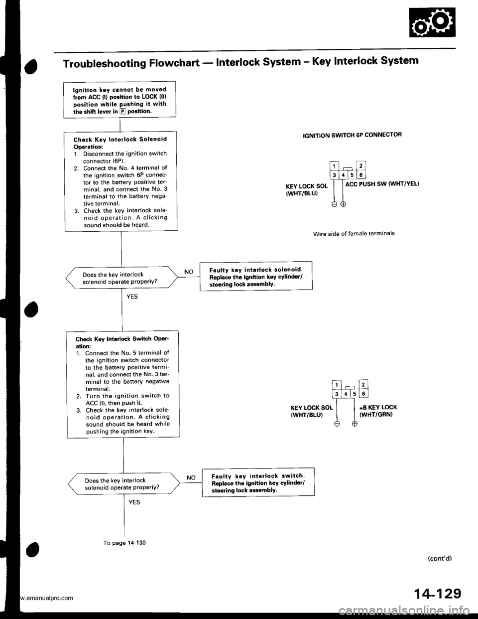
Troubleshooting Flowchart - Interlock system - Key Interlock system
IGNITION SWITCH 6P CONNECTOR
KEY LOCK SOL
IWHT/BLU)
ACC PUSH SW (WHT/YEL}
Wire side ot female terminals
KEY LOCK SOL
IWHT/BLUI
+B KEY LOCK(WHT/GRN)
(cont'd)
lgnition ksy cannot be moved
from ACC (l) pGition to LOCK (01
position while Pushing it with
the shift lever in E PGition.
Check Key lntorlock Solenoid
Operation:1. Disconnect the ignition switch
connector (6P).
2. Connect the No. 4 terminal of
the ignition switch 6P connec-tor to the battery Posative ter_minal, and connect the No. 3
terminal to the battery nega
tive terminal.3. Check the key interlock sole-no id operation. A clicking
sound should be heard.
F.ulty key interlock solenoid.
Replace tho ignition key cylinder/
steering lock asembly.
Does the key interlocksolenoid operate ProPerlY?
Ch€ck Key |motlock Switch OPer'etion:1. Connect the No. 5 terminal of
th€ ignition switch connectorto the battery Positive termi-nal, and connectthe No.3 teF
minal to the baftery negativetermrnal,2. TLrrn the ignition switch toACC (l), then PUsh it.3. Check the key interlock sole-noid operation. A clickingsound should be heard whilepushing the ignition kev.
Faulty key interlock 3witch.
Roplaco the ignidon key cylinder/
steoring lock tssamblY.
Does the key interlocksolenoid operate Properly?
To page 14-130
14-129
www.emanualpro.com
Page 651 of 1395
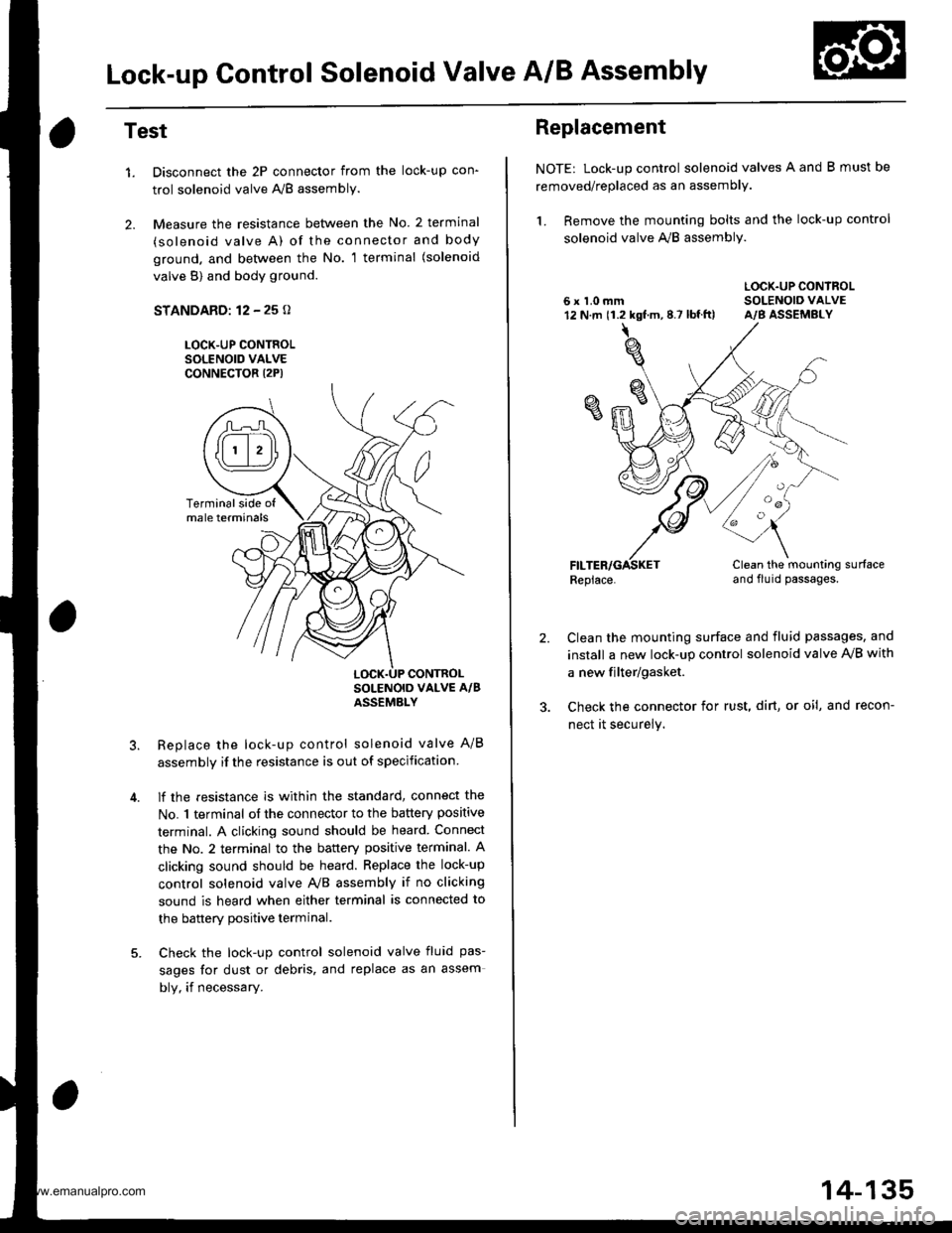
Lock-up Control Solenoid Valve A/B Assembly
Test
1.
2.
Disconnect the 2P connector from the lock-up con'
trol solenoid valve A'lB assembly.
Measure the resistance between the No. 2 terminal
(solenoid valve A) of the connector and body
ground. and bet\iveen the No. 1 terminal (solenoid
valve B) and body ground.
STANDARD: 12 - 25 o
LOCK-UP CONTROLSOLENOID VALVECONNECTOR I2P)
Replace the lock-up control solenoid valve A/B
assembly if the resistance is out of specification
lf the resistance is within the standard, connect the
No. 1 terminal of the connector to the battery positive
terminal. A clicking sound should be heard Connect
the No. 2 terminal to the battery positive terminal. A
clicking sound should be heard. Replace the lock-up
control solenoid valve Ay'B assembly if no clicking
sound is heard when either terminal is connected to
the banerv Dositive terminal.
Check the lock-up control solenoid valve fluid pas-
sages for dust or debris, and replace as an assem
bly, if necessary.
Terminalside ofmale terminals
LOCK.UP CONTROL
Replacement
NOTE: Lock-up control solenoid valves A and B must be
removed/replaced as an assembly.
1. Remove the mounting bolts and the lock-up control
solenoid valve A,,/B assembly.
LOCK.UP CONTROL6 x 1.0 mm SOLENOIO VALVE12 N.m 11.2 kgf.m,8.7 lbf.ft) A/B ASSEMBLY
Replace.Clean the mounting surfaceand flu id passages.
2.Clean the mounting surface and fluid passages, and
install a new lock-up control solenoid valve IVB with
a new filter/gasket.
Check the connector for rust, dirt, or oi!, and recon-
nect it securely.
oa
14-135
www.emanualpro.com
Page 652 of 1395
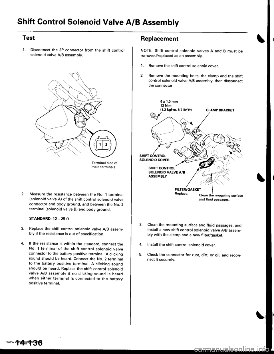
Shift Control Solenoid Valve A/B Assembly
Test
'1. Disconnect the 2P connector from
solenoid valve Ay'B assembly.
the shift control
Terminalsade ofmale terminals
Measure the resistance between the No. 1 terminal(solenoid valve A) of the shift control solenoid valve
connector and body ground, and between the No. 2terminal (solenoid valve B) and body ground.
STANDARD: 12 - 25 O
Replace the shift control solenoid valve A,/B assem-bly if the resistance is out of specification.
lf the resistance is within the standard. connect theNo, I terminal of the shift control solenoid valveconnector to the battery positive terminal. A clickingsound should be heard. Connect the No. 2 terminalto the battery positive te.minal. A clicking soundshould be heard. Replace the shift control solenoidvalve A/B assembly if no clicking sound is heardwhen either terminal is connected to the battervpositive terminal.
14-136
Replacement
NOTE: Shift control solenoid valves A and B must beremoved/replaced as an assembly.
1. Remove the shift control solenoid cover.
2. Remove the mounting bolts, the clamp and the shiftcontrol solenoid valve Ay'B assembly, then disconnect
the connector.
6x1.0mm12 N.m{1.2 k9 .m,8.7 lbtft}CLAMP ARACKET
FILTER/GASKETReplace.Clean the mounling surfaceand fluid passages.
Clean the mounting surface and fluid passages. andinstall a new shift control solenoid valve Ay'B assem-bly with the clamp and a new filter/gasket.
Install the shift control solenoid cover.
Check the connector for rust, dirt. or oil, and recon-nect it securely.
w
SHIFT CONTROLSoLENO|O COVEn
SHIFT CONTROLSOLENOID VALVE A/BASSEMBLY
\--
qK
-!t'">,,
www.emanualpro.com
Page 653 of 1395
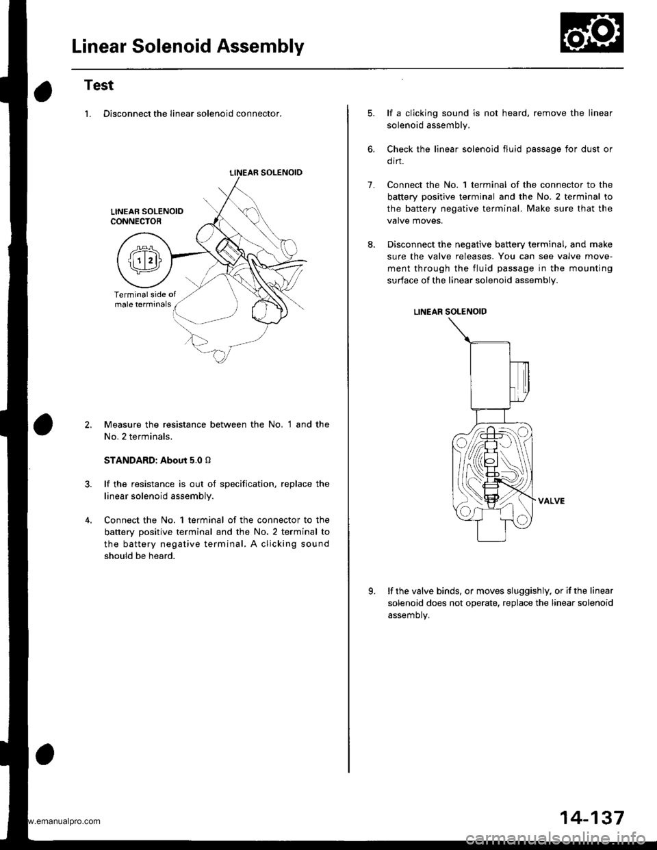
Linear Solenoid Assembly
Test
1. Disconnect the linear solenoid connector.
LINEAR SOLENOIO
Measure the resistance between the No, 1 and the
No. 2 terminals.
STANDARD: About 5.0 o
lf the resistance is out of specification, replace the
linear solenoid assembly.
Connect the No. 1 terminal of the connector to the
battery positive terminal and the No. 2 terminal to
the battery negative terminal, A clicking sound
should be heard.
1.
lf a clicking sound is not heard, remove the linear
solenoid assembly.
Check the linear solenoid fluid passage for dust or
orn.
Connect the No. 1 terminal of the connector to the
battery positive terminal and the No. 2 te.minal to
the battery negative terminal. Make sure that the
valve moves.
Disconnect the negative battery terminal. and make
sure the valve releases. You can see valve move-
ment through the fluid passage in the mounting
surface of the linear solenoid assembly.
LINEAR SOLENOID
VALVE
lf the valve binds, or moves sluggishly. or if the linear
solenoid does not operate, replace the linear solenoid
assemotv.
K
14-137
www.emanualpro.com
Page 663 of 1395
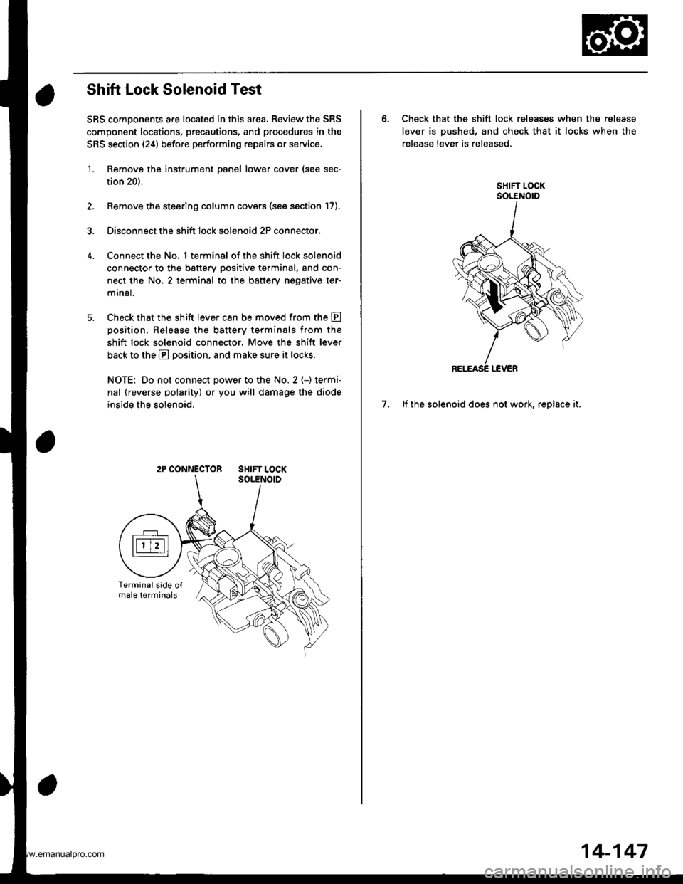
Shift Lock Solenoid Test
SRS components are located in this area. Review the SRS
component locations, precautions, and procedures in the
SRS section (24) before performing repairs or service,
'1. Remove the instrument panel lower cover (see sec-
tion 20).
2. Remove the steering column covers (see section 17).
3. Disconnect the shift lock solenoid 2P connector.
Connect the No. 1 terminal of the shift lock solenoid
connector to the battery positive tgrminal, and con-
nect the No. 2 terminal to the battery nogative ter-
mrnal.
Check that the shift lever can be moved from the E
oosition. Release the batterv terminals from the
shift lock solenoid connector. Move the shift lever
back to the E position, and make sure it locks.
NOTE: Do not connect power to the No. 2 (-) termi-
nal {reverse polarity) or you will damage the diode
inside the solenoid.
2P CONNECTOR SHIFT LOCK
6. Check that the shift lock releases when the release
lever is pushed, and check that it locks when the
release lever is released,
7. lf the solenoid does not work, replace it.
14-147
www.emanualpro.com
Page 685 of 1395

Transmission
Removal
@
2.
'1.
Make sure lifts. iacks, and safety stands aro placed
properly, and hoist brackets are attached to the col-
rest position on the engine lsee section 11.
Apply th€ parking brake and block the r€ar wheels,
so vehicls will noi roll off the stands and fall on you
while working under it.
NOTE: Use fender covers to avoid damaging painted
surfaces.
Disconnect the negative terminal, then disconnect
the positive terminal from the battery.
Remove the intake air duct and the air cleaner hous-
ing assembly,
Remove the starter cables. Remove the harness
clamp from the clamp bracket.
5.
STARTERCABLES
Remove the transmission ground cable terminal
and the radiator hose clamp lrom the transmission
hanger.
Disconnect the lock-up control solenoid valve con-
nector, then remove the harness clamp from the
clamp bracket.HARNESS CLAMP
RADIATOR HOSECLAMP
CONTROLSOLENOID VALVECONNECTOR
CLAMP
6. Disconnect the vehicle speed sensor (VSS), the coun-
tershaft speed sensor, and the A/T gear position
switch connectors.
A/T GEAR POSITIONSWITCH CONNECTOR
VEHICLE SPEEDSENSOR |VSS'
CONNECTORBfiACKET
SPEED SENSORCONNECTOR
7. Remove the transmission housing mounting bolts.
MOUNTING BOLTS
(cont'd)
14-169
www.emanualpro.com