1997 HONDA CR-V starter
[x] Cancel search: starterPage 363 of 1395
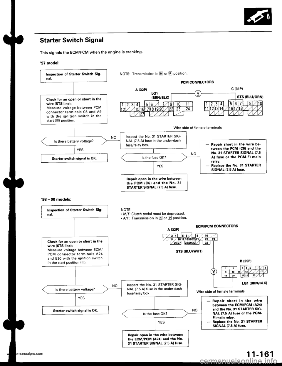
Starter Switch Signal
This signals the ECM/PCM when the engine is cranking.
'97 model:
A {32P}
'98 - 00 models:
Transmission in E or E position.
LGl(BBN/BLK)
PCM CONNECTORS
Wire side of female terminals
ECM/PCM CONI{ECTORS
STS (BLU/ORNI
c t31P)
NOTE:. M/T: Clutch pedal must be depressed.. A/T: Transmission in E orE position
Check for an opan ot short in the
wire (STS linel:Measure voltage between PCM
connector terminals C6 and Ag
with the ignition switch in the
start (lll) position.
lnspect the No. 31 STARTER SIG-
NAL (7.5 A)Illse in the under'dashls there battery voltage?- Reoair short in the wire be-
tween the PCM lc6l and th.No. 31 STARTER SIGNAL 17 5A) tuse ot the PGM-FI main
reray.- Reolace the No. 31 STARTERSIGNAL t7.5 Altu.e.
Starter swiich signal i3 OK.
Repair opon in the wire betweonrh6 PCM lc6l and the No 31
STARTER SIGNAL 17.5 A)fuse.
A (32P)
Wire side oI female terminals
Check tor an open or short in thewir€ (STS line):Measure voltage between ECM/
PCM connector terminals A24
and 820 with the ignition switchin the start position (lll).
Inspect the No. 31 STARTER SIGNAL (7.5 A){use in the under-dashls there battery voltage?
- Reoair shorl in the wire
betwe€n the ECM/PCM lA2,fland the No, 31 STARTER SIG-NAL t7.5 Al tu3€ ot the PGM'Fl main rclay.- Repl.c. tho No. 31 STARTERSIGNAL 17.5 Al fu3e.
Starter switch 3ignal is OK.
Repair opon in tho wire between
the ECM/PCM {A241 and the No
31 STARTER SIGNAL (7.5 A) tu3e
1 1-161
www.emanualpro.com
Page 382 of 1395
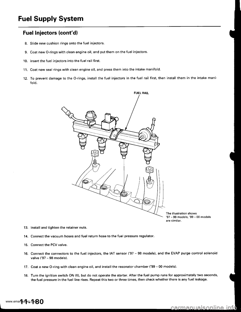
Fuel Supply System
Fuel Injectors {cont'dl
8. Slide new cushion rings onto the fuel injectors.
9, Coat newO-ringswith clean engine oil,and putthem onthefuel iniectors.
'10. lnsert the fuel injectors into the fuel rail first.
11. Coatnewseal ringswithclean engineoil,and press them into the intake manifold
12. To prevent damage to the O-rings, install the fuel injectors in the fuel rail first, then install them in the intake mani-
fold.
FUEL RAIL
The ill!stration shows'97 -98 models,'99 - 00 modelsare similar.
13. lnstall and tighten the retainer nuts.
14. Connect the vacuum hoses and fuel return hose to the fuel pressure regulator.
15. Connect the PCV valve.
16. Connect the connectors to the fuel injectors, the IAT sensor ('97 - 98 models), and the EVAP purge control solenoid
valve {'97 - 98 models).
Coat a new O-ring with clean engine oil, and install the resonator chamber ('99 - 00 models).
Turn the ignition switch ON (ll), but do not operate the starter. After the fuel pump runs for approximately two seconds,
the fuef pressure in the fuel line rises. Repeat this two or three times, then check whether there is any fuel leakage.
11.
18.
1 1-180
www.emanualpro.com
Page 390 of 1395
![HONDA CR-V 1997 RD1-RD3 / 1.G Workshop Manual
Fuel Supply System
PGM-FI Main Relay (contdl
Troubleshooting
lc(}21PGM.FI MAIN RELAY 7P CONNECTOR
GND
trTr]--Flq
FI,TilI A
Y
Wire side ot female terminals
- Engine will not start.- InsDection ol PG HONDA CR-V 1997 RD1-RD3 / 1.G Workshop Manual
Fuel Supply System
PGM-FI Main Relay (contdl
Troubleshooting
lc(}21PGM.FI MAIN RELAY 7P CONNECTOR
GND
trTr]--Flq
FI,TilI A
Y
Wire side ot female terminals
- Engine will not start.- InsDection ol PG](/manual-img/13/5778/w960_5778-389.png)
Fuel Supply System
PGM-FI Main Relay (cont'dl
Troubleshooting
lc(}21PGM.FI MAIN RELAY 7P CONNECTOR
GND
trTr]--Flq
FI,Til'I A
Y
Wire side ot female terminals
- Engine will not start.- InsDection ol PGM-FI mainrelay and relay harness,
Check fo. an open in the wireIGND linol:1. Turn the ignition switch OFF.2. Disconnect the PGM Fl mainrelay 7P connector.3. Check for continuity betweenthe PGM'FI main relay 7P con-nector terminal No. 3 and bodyground.
Repair opcn in th€ wire betweenthe PGM-FI main relav and G101.
Check tor an open or short in thewiro (BAT line):Measure voltage between thePGM'FI main relay 7P connectorterminal No. 7 and body ground.- Repai. open or short in lhewir6 belween the PGM-FImain relay and the Fl E/M (15Al fu3e.- Replace th6 FIE/M (15 Altus6in th€ under-hood fuse/.6lay
ls there baftery voltage?
Check lor an open or short in thewire (lGl line):L Turn the ignition switch ON (ll).2. Measure the voltage betweenthe PGM-FI main relay 7P connectorterminal No. 5 and bodyground.- Repair open or shorl in thewire between the FGM-FI mainrelay and the No. 13 FUELPUMP 115 A) tuse.- Replaco the No. 13 RJEL PUMP115 A) luse in the und6.-d$hfuso/ relav box.Check for an open or short in thewire {STS line):1. Turn the ignition switch to theSTART (lll) position.NOTE:. M/T: Clutch pedal must bedepressed.. A/T: Transmission in E orElposition.2. Measure the voltage betweenthe PGM-Fl main retay 7Pconnector terminal No. 2 andbody ground.- Repair open or short in thewire betwe€n the PIGM-FI m.inrclay and th€ No. 31 STARTERSlGllAL 17.5 A) tuse.- Repl.ce the No. 31 STARTERSIGNAL 17.5 Al tuse in theunder-dash tuse/relay box.('97 model: To page 11-189)('98 00models:To page 1l 190)
1 1-188
www.emanualpro.com
Page 446 of 1395
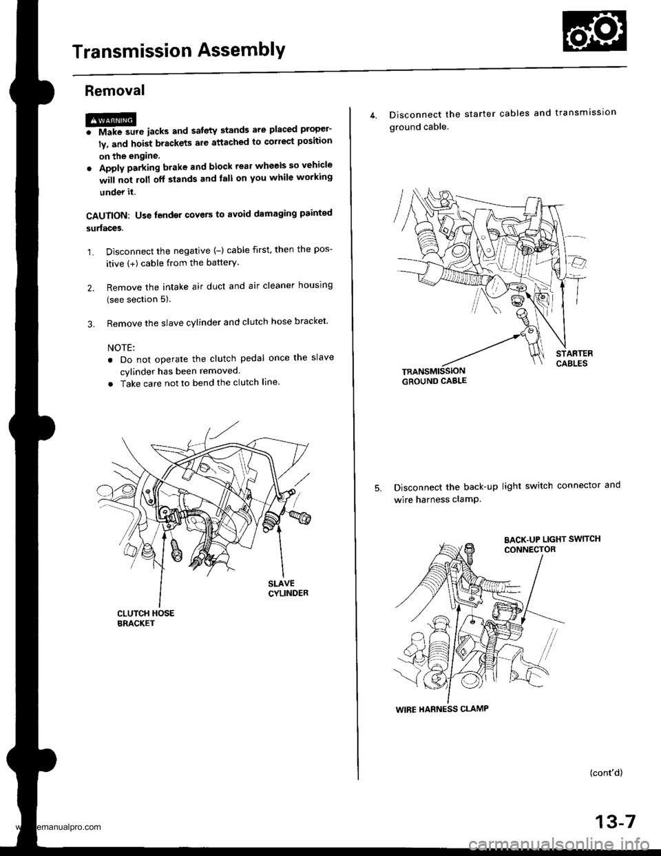
Transmission AssemblY
Removal
@FMak. sw. iack" and safety stands are placed propel-
ly, and hoist brackets are attached to collect position
on the engine,
. Apply parking brake and block rear wheels so vehicle
will not roll off stands and lall on you while working
under it.
CAUTION: Use fender covers to avoid damaging painted
surfaces.
1. Disconnect the negative {-) cable first, then the pos-
itive (+) cable from the batterY.
2. Remove the intake air duct and air cleaner houslng
(see section 5).
3. Remove the slave cylinder and clutch hose bracket'
NOTE:
. Do not operate the clutch pedal once lhe slave
cvlinder has been removed.
. Take care not to bend the clutch line.
4. Disconnect the
ground cable.
starter cables and transmission
TRANSMISSIONGROUND CABLE
Disconnect the back-up light switch connector and
wire harness clamP.
(cont'd)
13-7
WIRE HARNESS CLAMP
www.emanualpro.com
Page 450 of 1395
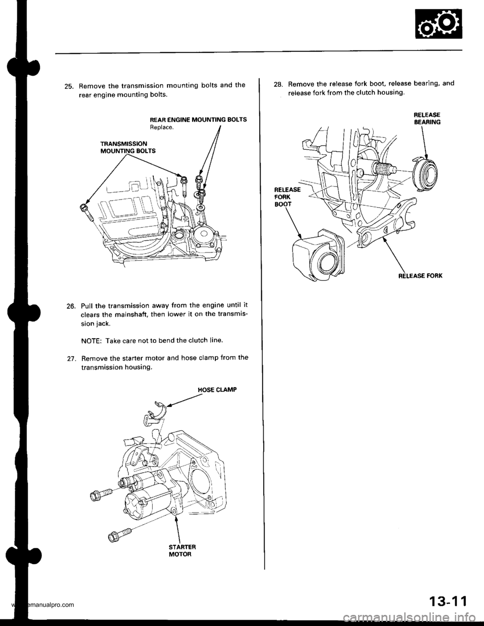
25. Remove the transmission mounting bolts and the
rear engine mounting bolts.
REAR ENGINE MOUNTING BOLTSReplace.
TRANSMISSION
Pull the transmission away from the engine until it
clears the mainshaft, then lower it on the transmis-
sion jack.
NOTE: Take care not to bend the clutch line.
Remove the starter motor and hose clamp from the
transmission housing.
STARTERMOTOR
28. Remove the release tork boot. release bearing, and
release fork from the clutch housing
RELEASEBEANING
13-1 1
www.emanualpro.com
Page 511 of 1395
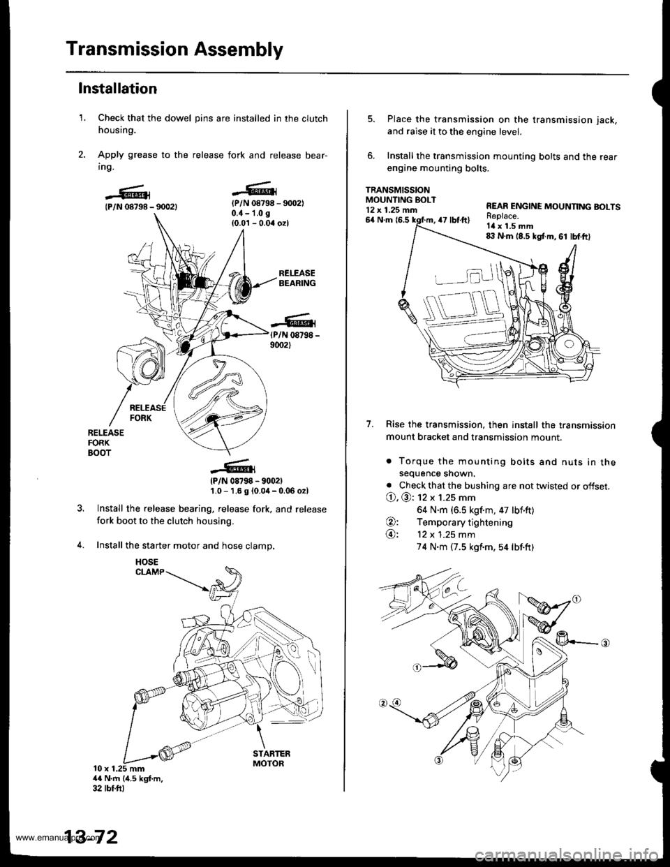
Transmission Assembly
1.
Installation
Check that the dowel pins are installed in the clutch
housing.
Apply grease to the release fork and release bear-
ing.
{P/N 08798 - 90021{P/N 08798 - 9002)0.{ - 1.0 g
{0.0'l - 0.04 ozl
RELEASEBEARING
(P/N 08798 -
9002)
RELEASEFORKBOOT
?
(P/N 08798 - 9002)'1.0 - 1.6 g {0.0,1- 0.06 o2l
Install the release bearing, release fork, and release
fork boot to the clutch housing.
Install the starter motor and hose clamp.
10 x 1.25 mm4{ N'm (4.5 kgf.m,32 tbf.ftl
13-72
HOSE
5. Place the transmission on the transmission jack,
and raise it to the engine level.
6. Install the transmission mounting bolts and the rear
engine mounting bolts.
TRANSMISSIONMOUNTING EOLT12 x 1.25 mn
7.
64 N.m {6.547 tbt.ft)
REAR ENGINE MOUNNNG BOLTSReplace.Itl x 1.5 mm8:l N.m 18.5 kgt m, 61 lbf.ft)
Rise the transmission, then install the transmission
mount bracket and transmission mount.
. Torque the mounting bolts and nuts in thesequence shown.
. Check that the bushing are not twisted or offset.
O. @: 12 x 1.25 mm
64 N.m (6.5 kgf.m, 47 lbf'ft)
O: Temporary tightening
@: 12 x 1.25 mm
74 N.m (7.5 kgf'm,54 lbf.ft)
www.emanualpro.com
Page 515 of 1395
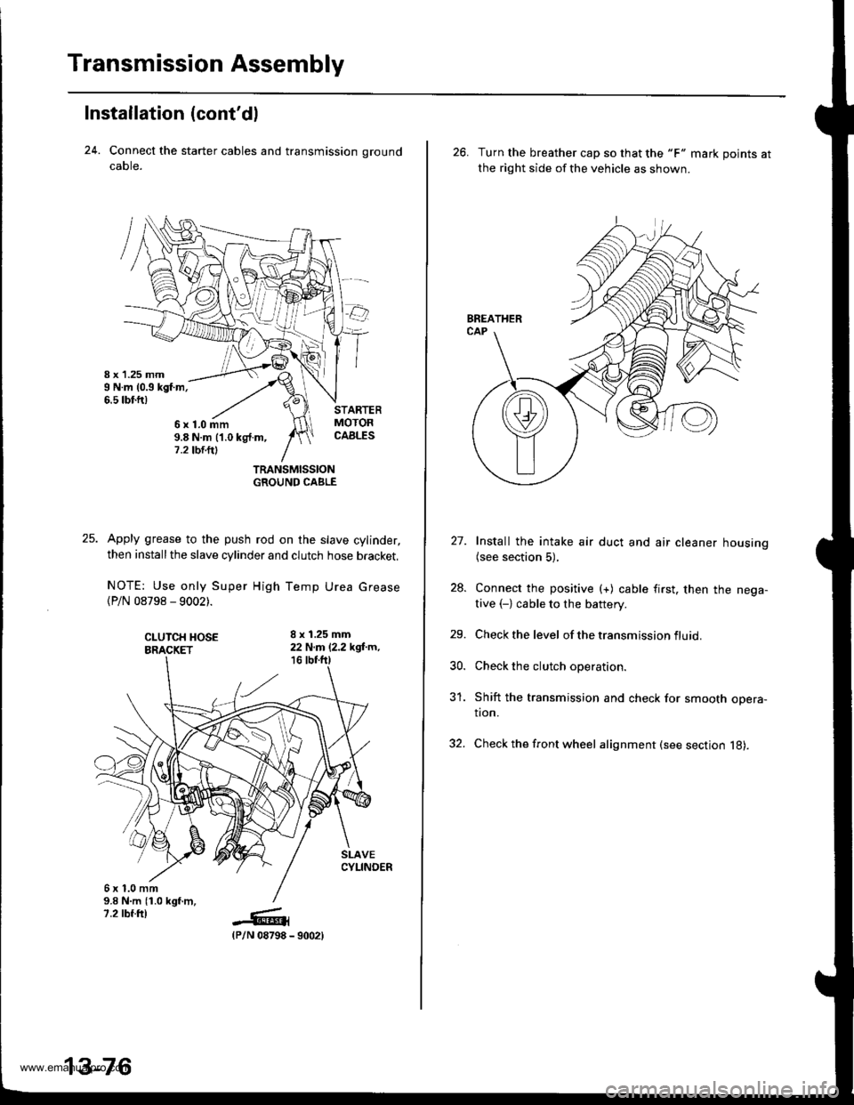
Transmission Assembly
Installation (cont'dl
24. Connect the starter cables and transmission ground
caore.
TRANSMISSIONGROUND CABLE
Apply grease to the push rod on the slave cylinder,
then install the slave cylinder and clutch hose bracket,
NOTE: Use only Super High Temp Urea Grease
{P/N 08798 - 9002).
CI-UTCH HOSEBRACKET
8 x 1.25 mm22 N.m 12.2 kgi-m,16 tbr.f0
6x1.0mm9.8 N.m {1.0 kgf.m,7.2 rbf.ftt_G1(P/N 08798
6x1.0mm9.8 N.m (1.0 kg{.m,7.2 tbt.ttl
13-76
- 9002)
26. Turn the breather cap so that the "F" mark points at
the right side of the vehicle as shown.
27. Install the intake air duct and air cleaner housing(see section 5),
28. Connect the positive (+) cable first. then the nega-
tive (-) cable to the battery.
29. Check the level of the transm ission f lu id.
30. Check the clutch operation.
31. Shift the transmission and check for smooth opera-tion.
32. Check the front wheel alignment (see section l8).
www.emanualpro.com
Page 519 of 1395

Description
General Operation
The Automatic transmission is a 3-element torque converter and triple-shaft electronically controlled unit which provides 4
speeds forward and 1 reverse speed The unit is positioned in line with the engine'
There are two tvoes of automatic transmission on CR-V; the four-wheel drive (4WD) model ('97 - 00)' and the front-wheel
drive (2WD) model ('98 - 00).
Toroue Converter, G€ars, and Clutches
The torque converter consists of a pump. turbine. and stator assembly in a single unit. The torque converter is connected to
the engine crankshatt. These parts turn together as a unit as the engine turns. Around the outside of the torque converter is
a ring gear which meshes with the starter pinion when the engine is started. The torque converter assembly serves as a fly-
wheel while transmitting power to the transmission mainshaft.
The transmission has three parallel shafts: the mainshaft. the countershaft, and the sub-shaft. The mainshaft is in line with
the engine crankshaft. The mainshaft includes the 1st, 2nd. and 4th clutches, and gears lor 3rd,2nd,4th. reverse and 1st
(3rd gear is integral with the mainshaft, while reverse gear is integral with the 4th gear). The countershaft includes the 3rd
clutch and gears for 3rd,2nd, 4th, reverse, 1st, and park. Reverse and 4th gears can be locked to the countershaft at its cen-
ter, providing 4th gear or reverse, depending on which way the selector is moved. The sub-shaft includes the lst-hold
clutch and gears for lst and 4th.
The gears on the mainshaft are in constant mesh with those on the countershaft and sub-shaft. When certain combinations
of gears are engaged by the ctutches, power is transmitted from the mainshaft to the countershaft to provide E, D!, tr, tr,
and E position ('97 - 98 models). and E. E, E, and E position ('99 - 00 models)'
Electlonic Control
The electronic controt system consists of the Powenrain Control Module (PCM), sensors, a linear solenoid, and four
solenoid valves. Shifting and lock-up are electronically controlled for comfortable driving under all conditions. The PCM is
located below the dashboard, under the kick panel on the passenger's side.
Hydraulic Control
The valve bodies include the main valve body, the secondary valve body, the regulator valve body, the servo body, and
the lock up valve body. They are bolted to the torque converter housing. The main valve body contains the manual valve,
the 1-2 shift valve, the 2nd orifice control valve. the CPB {Clutch Pressure Back-up) valve, the modulator valve, the servo
control valve. the relief valve, and ATF pump gears. The secondary valve body contains the 2-3 shift valve, the 3-4 shift
valve, the 3,4 orifice control valve. the 4th exhaust valve and the CPC (Clutch Pressure Control) valve. The regulator valve
bodv contains the pressure regulator valve, the torque converter check valve, the cooler relief valve, and the lock-up con-
trol valve. The servo body contains the servo valve which is integrated with the reverse shift tork, and the accumulators
The lock-up valve body contains the lock-up shift valve and the lock-up timing valve. The linear solenoid and the shift con-
trol solenoid valve Ay'B are bolted to the outside of the transmission housing, and the lock-up control solenoid valve Ay'B is
bolted to the outside of the torque converter housing. Fluid trom the regulator passes through the manual valve to the
various control valves. The clutches receive fluid from their respective feed pipes or internal hydraulic circuit
ShiftControl Mechanism
input from various sensors located throughout the vehicle determines which shift control solenoid valve the PCM will acti-
vate. Activating a shift control solenoid valve changes modulator pressure, causing a shift valve to move. This pressurizes
a line to one of the clutches. engaging that clutch and its corresponding gear. The shift control solenoid valves A and B are
controlled by the PCM.
Lock-up Mechanism
tn E! position (,97 - 98 modets) and in E position ('99 - O0 models), in 3rd and 4th, and in Del position in 3rd ('97 - 98
models) and in El position with Over,Drive (O/D) is OFF (by pressing rhe O/D switchl in 3rd ('99 - 00 models), pressurized
fluid is drained from the back of the torque converter through a fluid passage, causing the lock-up piston to be held
against the torque converter cover, As this takes place, the mainshaft rotates at the same speed as the engine crankshaft.
Together with hydraulic control, the PcM optimizes the timing of the lock-up mechanism The lock-up valves control the
range of lock-up according to lock-up control solenoid valves A and B, and the linear solenoid. When lock-up control
solenoid valves A and B activate, the modulator pressure changes. The lock-up control solenoid valves A and B and the
linear solenoid are controlled by the PCM.
{cont'd)
14-3
www.emanualpro.com