Page 54 of 1395
Starting System
Circuit Diagram
IGN TIONSWITCH
/ BAI \-+o cf-.|
\i7 IBLKMHT
II
I
tl
tlELKMHT BLK'WHT
STARTEFCUl RELAY
I A/T GEAR PosrroN!i swrTcH (A/T) |l/oN EorN |l p.siton / :!-- -_ --___J
f';--"-lI TNTERLooK I
fYl""yl, I
GRY
IGRN
8LK
Gl0l
UNDER.HOOD FUSE/RELAY 8OX
N0.41 (100A) N0.42 (40A)
-.1
BLKRED
I
IGNITION CONTROLMOoULE ( CM)
STARTEB(Field wnd ng lype)
4-4
www.emanualpro.com
Page 65 of 1395
Circuit Diagram
IGNIT ONSW TCHUNDEF,DASHFUSEi RELAY BOX
6 l;;l Eci,.pcMi{Hr6-(-\9-'-'*'.--EII
V'il
IGN TIONW]BES
SPARKPLUGS
I l: '99 - 00 modelsGt01
4-15
UNDEF.HOOD FUSE/RELAY 8OX
f l-- r
TDC Top dead cenlerCKP Cran[shan poslionCYP Cylnder posrlon
TDC/CKP/CYP SENSOR
BLK/YEL
l^IGNITIONcotL
IGN]TION CONTROLMODULE (CM)
/ Has buil-if \I no|se l
i l' i--, -BLUll
ifrI BLU BLU I
ll/' i
| | resrI TACHOMETER
I I
tott"to*
LTTCHoMEIEB j'97 -'98 models
IJltfi--cMFcr,r
I
www.emanualpro.com
Page 87 of 1395
UNDER.OASH FUSARELAY BOX
INDICATORLIGHT(0.84W)
lPIOSET
526712813
CRUISE CONTROT UNLT 10
11114
COMEINATONL GH'I SWITCH
f7
IRED/BLK
Gircuit Diagram
*: '98 00 models withAutomatic Transmission.
J
BRAK€LGHTSPNK BLK BLK
I L_l
tl
4F /lr,mcern I I
Y{"^ i?tr'.flffi'JF ) l
I
t loN : Pedar rereasedl /l
8LK BLK
TI
G101 G401
CRUISECONTROLACTUATOR
t'BLK
n:
G202
IGNIT ONSWITCHUNDER.HOOD FUSEi RELAY BOX
No 41 (100A) No 42 (404)
4-37
www.emanualpro.com
Page 201 of 1395
Circuit Diagram
UNDER OASHFUSEiRELAY BOX
6; E;';lwHTsLka rtF',*",El-l
I
RAOIATORFANSWITCHfClosed :Above)L 199oF {930C) J
BLK/RED
I
L^,^,.,
T*'
IBLK
I
I
oro,
IGNITION SWITCH
No.41{100A) N0.42140A)
www.emanualpro.com
Page 386 of 1395

Fuel Supply System
Fuel Gauge
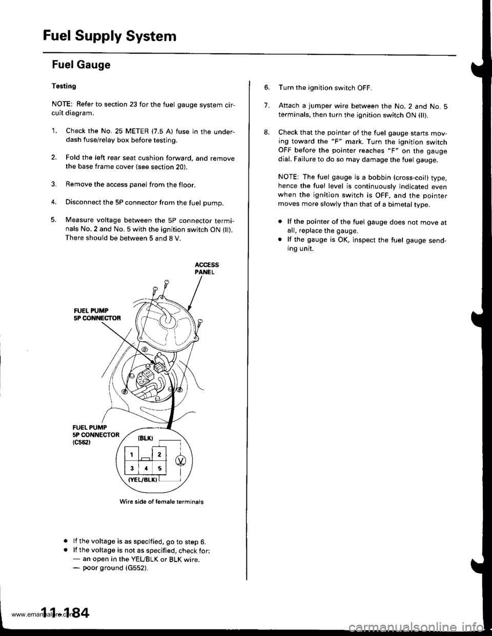
Tssting
NOTE: Refer to section 23 for the fuel gauge system cir-cuit diagram.
'1. Check the No. 25 METER (7.5 A) fuse in the under-dash fuse/relay box before testing.
2. Fold the left rear seat cushion forward, and remove
the base frame cover {see section 20).
3. Remove the access panel from the floor.
4. Disconnect the 5P connector from the fuel pump.
5. Measure voltage between the 5P connector termi-nals No.2 and No. 5 with the ignition switch ON ( ).There should be between 5 and 8 V.
FUEL PUMP5P CONNECTOR
tc56al
a
a
Wire side of female t€rminals
lf the voltage is as specified, go to step 6.lf the voltage is not as specified, check for:- an open in the YEUBLK or BLK wrre.- poor ground (c552).
11-184
7.
Turn the ignition switch OFF.
Attach a jumper wire between the No. 2 and No. 5terminals, then turn the ignition switch ON fll).
Check that the pointer of the fuel gauge starts mov-ing toward the "F" mark. Turn the ignition switchOFF before the pointer reaches "F" on the gauge
dial. Failure to do so may damage the luel gauge.
NOTE: The fuel gauge is a bobbin (cross-coil) type,hence the fuel level is continuously indicated evenwhen the ignition switch is OFF, and the pointer
moves more slowly than that of a bimetal type.
. lf the pointer of the fuel gauge does not move atall. replace the gauge.
. lf the gauge is OK, inspect the fuel gauge send-ing unit.
www.emanualpro.com
Page 948 of 1395

Anti-lock Brake System (ABSI,'97 - 00 Models
Special Tools ............. 19-26
Component Locations ......................... 19-27
Anti-lock Brake System (ABS)
Features/Construction ............. ......, 19-2A
Circuit Diagram ......... 19-32
ABS Control Unit Terminal
Arrangement ......... 19-34
Troubleshooting Precautions ............. 19-36
Diagnostic Trouble Gode (DTC)
Diagnostic Trouble Code (DTC)
Indication (SCS Model ................ 19-38
DTG Erasure (MES Mode) ............... 19-39
Troubleshooting lndex .................... 19-40
Troubleshooting
ABS Indicator Light Does Not
Come On ............ 19-41
ABS Indicator Light Does Not
Go Off (No DTC) ........................... 19-43
DTC 1r - 18:
Wheel Sensor .... 19-45
DTC 31 - 38:
Solenoid ............. 19-47
DTC 51 - 53:
ABS Pump Motor ......................... 19-49
DTC 54:
Main Relay ......... 19-52
DTC 61:
lgnition Voltage ........................... 19-54
DTC 81:
Central Processing Unit (CPU) .... 19-55
Modulator Unit
Removal/lnstallation ....................... 19-56
ABS Control Unit
Replacement ..,...... 19-57
Pulsers/Wheel Sensors
Inspection .............. 19-57
Wheel Sensor Replacement ............ 19-58
www.emanualpro.com
Page 955 of 1395
Circuit Diagram
UNDFS I]OOD FISAFELAY 8OXCbsod: &rrc ped. deprelled
wHT/GrN -tjF GFrlrr'vril
GNITION
*oJG\'*"\€F*,-
UNDER-HOOD A8S FUSE/FELAY BOX3P CONNECTOR (O number)
t_--t l-|ll'"1
UNDER.HOOO A8S FUSE/RELAY BOX2P CONNECTOF (! numbor)
EFIAKE SWITCH CONNECTOR
l€-4| 1 txl2 |
f s a'lLr--'--.----1
UNDER,DASH FUSFJRELAY BOX20P CONNECTOR (O number)M-OD U LATOR UN IT CON N ECTOR
ll3 2ir I
{tT6TsF}
!]q:]j_1,
MP MOTOR CONNECTORnumber)
ATi)
PU
UNDER-DASH FUSE/RELAY BOX18P CONNECTOR (E number)
(tr
ASSEMBLY 5P CONNECTOR
----.4-l1)/l3l/l5l
356J89
10111213,/ 115 ,/19
123456
910'1213|i4 /718
19-32
Wire side ol female lerminals
Terminal side oJ lemale terminals
www.emanualpro.com
Page 1098 of 1395
Circuit Diagram
UNDER.DASHFUSEiRELAY BOXIGNIT ON SWITCHUNDEB HOOD FUSE/RELAY BOX
/6'^' F;t"^i IwHTBLK + **f ,o+trrffl- eLK/YEI f
\_-./
,JCPRESSURESWITCN2 /: 1Btu/RED -{.-!}- Btu/yvHT\,-/
BLU'ryVHTBLK
G401G402
RED
I,
mI d I CoMPRESSORI I I CLUTCH
LIl
I
CONDENSER
MOTOR
BLK/RED GRN WHT
I I,^,^,", I
L^"^,Y**t,|
T*.'1 Y
lllBLK BLK BLK
rtl
lll---
G201 G101 G202
COMPRESSOFCLUTCHRELAY
22-8
www.emanualpro.com