Page 93 of 1395

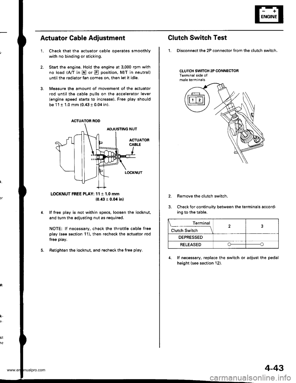
Actuator Cable Adiustment
'1.Check that the actuator cable operates smoothly
with no binding or sticking.
Start the engine. Hold the engine at 3,000 rpm with
no load (A,/T in E or E position, M/T in neutral)
until the radiator fan comes on, then let it idle.
Measure the amount of movement of the actuator
rod until ths cable pulls on the accelerator lever
(engine speed starts to increase). Free play should
be 11 t 1.0 mm (0.43 i 0.04 in).
LOCKNUT FREE PLAY: 11 t 1.0 mm
10.43 r 0.04 in)
lf free play is not within specs, loosen the locknut,
and turn the adjusting nut as requirsd,
NOTE: lf necessary, check the throttl€ cable frso
play (s€e section 11), then recheck the actuator rod
free play.
Retighten the locknut, and recheck the free play.
st
te
ACTUATOR ROD
Clutch Switch Test
1. Disconngct ths 2P connector from the clutch switch.
CLUTCH SWITCH 2P CONNECTORTerminalside ofmale terminals
2.
5.
Remove the clutch switch,
Check for continuity between the terminals accord-
ing to the table.
4. lf necessary, replace the switch or adjust the pedal
height (see section t2).
Terminal
Clutch Switch \
OEPRESSED
RELEASEDoo
4-43
www.emanualpro.com
Page 129 of 1395

Gylinder Head
Removal
Engine removal is not required for this procedure.
l!@ Make sure iacks and safety stands are
placed properly, and hoist blackels ale attachgd to the
correct position on the engine.
NOTE:
o Use fender covers to avoid damaging painted sur-
faces.
o To avoid damage, unplug the wiring connectors care-
fully while holding the connector portion.
. To avoid damaging the cylinder head, wait until the
engine coolant temperature drops below 100"F (38'C)
before loosening the retaining bolts.
. Mark all wiring and hoses to avoid misconnection.
Also, be sure that they do not contact other wiring or
hoses, or interfere with other parts.
2.
4.
5.
1.Disconnect the negative terminal from the battery.
Drain the engine coolant (see page 10-5). Remove
the radiator cap to speed draining.
Remove the intake air duct and air cleaner housing(see page 5-2).
Remove the mounting bolt and lock bolt, then
remove the power steering (P/S) pump belt and
pump (see page 5-4).
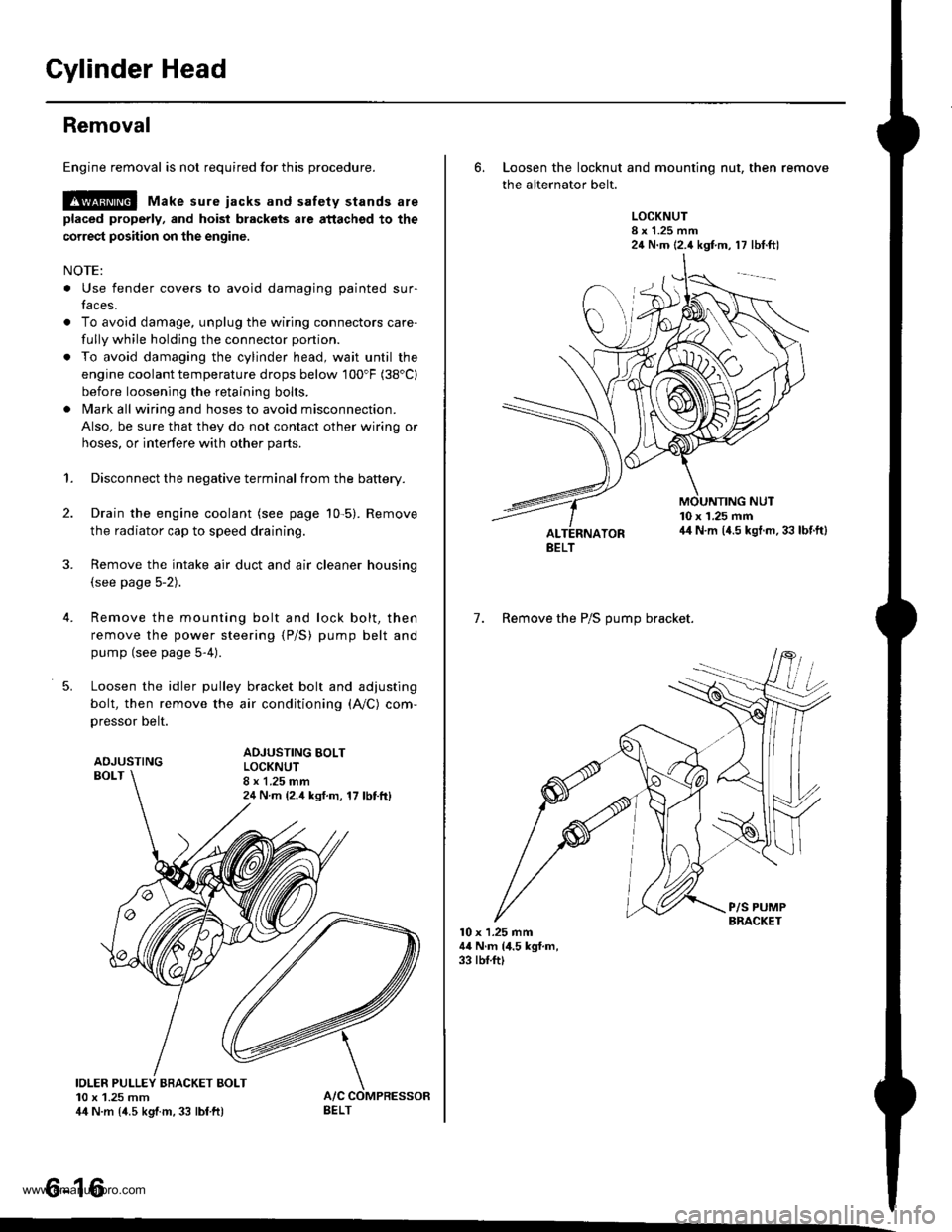
Loosen the idler pulley bracket bolt and adjusting
bolt, then remove the air conditioning (A,/C) com,
pressor belt.
ADJUSTINGBOLT
ADJUSTING BOLTLOCKNUT8 x 1.25 mm24 N m {2.4 ksf.m, 17 lbttt}
IOLER PULLEY BBACKET BOLT10 x 1.25 mm44 N.m {4.5 kgtm, 33 lbf ft)
tt aAo-Io
6. Loosen the locknut and mounting nut, then remove
the alternator belt.
LOCKNUT8 x 1.25 mm24 N.m (2.4 kgf.m, 17 lbt.ftl
10 x 1.25 mm44 N.m (4.5 kgt.m. 33 lbf.ft)
7. Remove the P/S OUmo bracket.
l0 x 1.25 mm44 N.m (4.5 kgf.m,33 rbf.ft)
BELT
www.emanualpro.com
Page 167 of 1395

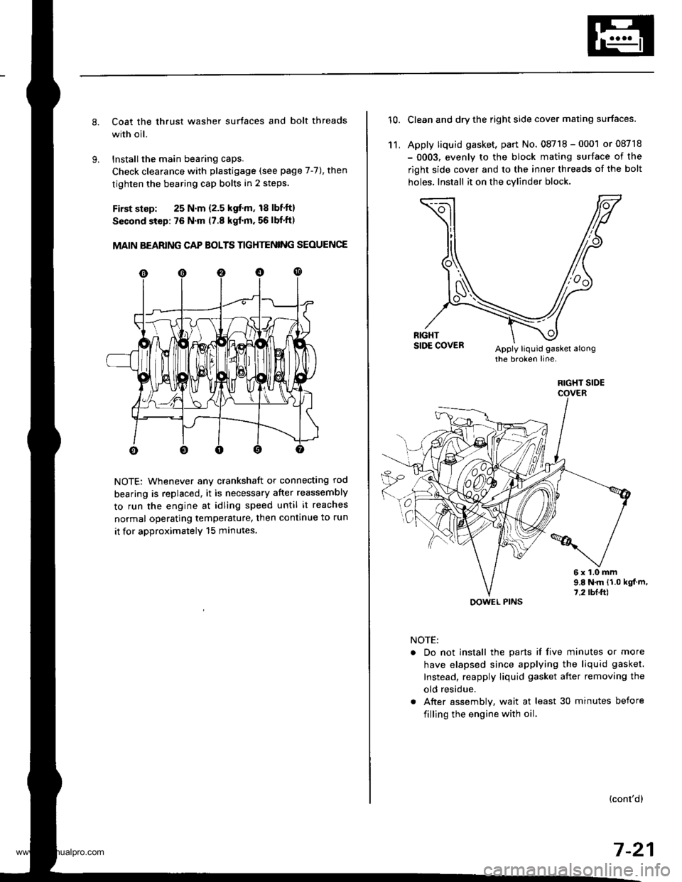
Coat the thrust washer surtaces and bolt threads
with oil.
Installthe main bearing caps.
Check clearance with plastigage (see page 7-7), then
tighten the bearing cap bolts in 2 steps.
First slsp: 25 N.m {2.5 kgf'm, 18 lbf'ft}
Sscond step: 76 N'm (7.8 kgf'm. 56 lbf'ft)
MAIN BEARING CAP BOLTS TIGHTENING SEOUENCE
NOTE: Whenever any crankshaft or connecting rod
bearing is replaced, it is necessary after reassembly
to run the engine at idling speed until it reaches
normal operating temperature, then continue to run
it for approximatelY 15 minutes.
10.Clean and dry the right side cover mating surfaces.
Apply liquid gasket, part No. 08718 - 0001 or 08718
- 0003, evenly to the block mating surface of the
right side cover and to the inner threads of the bolt
holes. Install it on the cylind€r block
11,
6x1.0mm9.E N.m {1.0 kgt m,7.2 tbf.ft)
NOTE:
. Do not install the parts if five minutes or more
have elapsed since applying the liquid gasket.
Instead, reapply liquid gasket after removing the
old residue.
. After assembly, wait at least 30 minutes before
filling the engine with oil.
(cont'dl
7-21
RIGHT SIDE
OOWEL PINS
www.emanualpro.com
Page 204 of 1395

Fuel and Emissions
Special Tools ...................... 11-2
Component Locations
lndex ...................... ....,.... 11-3
Svstem Description
Vacuum Connections ...........,....,.,................. 1 1-9
Electrical Connections ................................... 1 1-15
System Connectors .,.,,.,............................,.,. 1 1-36
Troubleshooting
Troubleshooting Procedures,.,..................... 11-60
Engine Control Module/Powertrain ConttolModule Terminal Arrangement .............., 11-67
Diagnostic Trouble Code Chart .................... 1 t-75
How to Read Flowcharts .......,.....,.,............... I 1-79
PGM-Fl System
System Description .................,.,.,,,............... 1 1-80
Troubleshooting Flowcharts
Engine Control Module/PowertrainControl Module ........11-52
Manifold Absolute Pressure Sensor ............. 11-90
Intake Air Temperature Sensor .................... 1 1-95
Engine Coolant Temperature Sensor .,..,.,.... 1 1-99
Throttle Position Sensor ...........,.....,.,.,..,...... I 1'103
Primary Heated Orygen Sensor (Sensor 1) ... 11-110
Secondary Heated Oxygen Sensor{Sensor 2l .................. 1 1-117
Heated Oxygen Sensor Heater ..................... 11-121
Fuef Supply System ......11-124
Random Misfire ,....,.,..... 11-126
Mistire Detected in One Cylinder .....-........... 11-128
Knock Sensor ................ 11-130
CKP/TDC/CYP Sensor .................................... 1 1-131
Vehicle Speed Sensor ...............................,.... 1 1-135
Barometric Pressure Sensor .....,...,...,.,,........ 1 1-137
Electrical Load Detector ...,.,.......................... 1 1-138
CKF Sensor ................,.,, '11-112
ECM/PCM lnternaf Circuit ............................. 11'117
HO2S Replacement .,.,.,. 11-148
ldle Control System
System Description ............ 11-149
Troubleshooting Flowcharts
ldle Control System ...... 11-150
fdle Air Control Valve ......................,............. 11-152
Air Conditioning Signal ................................. I 1-155
Alternator FR Signal ...................................... 1 1-159
Starter Switch Si9na1 .................................... t l-161
Power Steering Pressure Switch Signal ...... 11-162
Brake Switch Si9na1 ...................................... 11-166
Fast ldle Thermo Valve .,.,.............................,.,.,. 11-168
ldle speed setting .............. 11-169
Fuel Supply System
Fuel Lines ............................ 11-171
Fuef Tube/Ouick-Conneci Fittings ..................... 11 -175
System Description ............ 11-178
Fuel Pressurg ...................... 11-178
Fuel Iniectors ................,..... 11-179
Fuel Pressure Re9u1ator .............................,.,...., f 1-181
Fuef Fifter ....,.,.,.,,,,.,............11-142
Fuel Pump ........................... 11-183
Fuel Gauge .......................... 11-184
Fuel Gauge Sending Unit ................................... I 1-185
Low Fuel Indicator System ...........,.,..,............... 1 1-185
PGM-FI Main Relay ............. 11-187
Fue|Tank................ ............. 11-191
Intake Air System
System Description ............ 11-193
Air Cleanel ,.,.,..................... 11-194
Throttle Cable ..................... 11-194
Throttle Body........ .............. 11-196
Emission Control System
System D$cription ...,....,.,. 11-199
Tailpipe Emission ............... 11-199
Three Way Catalytic Converter ..................,.,...,, 11-199
Positive Crankcase Ventilation System .,.,,,,.,.., 11-2O1
Evaporative Emission Controls .........,.,.,............ 11-203
www.emanualpro.com
Page 206 of 1395
Component Locations
lndex
'97 - 98 models:
MANIFOLD ABSOLUTEPRESSURE IMAP} SENSORTroubleshooting, Page 1 1-90
THROTTLE POSITION (TP}
SENSORTroubleshooting, page 1 1-103
toLE AtR CONTROL llAcl VAI-VE
Troubleshooting, page 1 1-152
EVAPORATIVE EMISSION (EVAP)
CONTROL CANISTER VENT SHUTVALVE t'98 mod€llTroubleshooting, page 11'213
INTAKE AIR TEMPERATUREIIATI SENSORTroubleshooting. page 1 'l -95
ELECTRICAL LOADDETECTOR IELD) (USA modol)Troubleshooting, page 1 1-138
VEHICLE SPEEDSENSOR (VSS)
Troubleshooting,page 11'135
CRANKSHAFTPOSTTtON/
POWER STEERING PRESSURElPsPl swtrcHTroubloshooting, page 1 1-162
TOP OEAD CENTER/CYLINDERPOStTtON{CKP/TDC/CYP} SENSOR(Built into the distributor)Troubleshooting, page 1 l-131
CMNKSHAFT SPEEDFLUCTUATION ICKF} SENSORTroubleshooting. page 1'!-142
ENGINE COOLANTTEMPERATUREIECTI SENSORTroubleshooting, page 11 99
EVAPORATIVEI€VAP) PURGE CONTROLSOLENOID VALVETroubf eshooting, page 1 1'2o5, 213
(cont'd)
11-3
www.emanualpro.com
Page 207 of 1395
Component Locations
Index (cont'dl
39 - 00 models:
MANIFOLD ABSOLUTEPRESSURE IMAPISENSORTroubleshooting, page 1 1-90
THROTTLE POSITION {TP)SENSORTroubleshooting, page 1 1-103
IDLE AIR CONTROL OACI VALVETroubleshooting, page 1 1-152
EVAPOBATIVE EMISSION {EVAPICONTROL CANISTER VENT SHUTVALVETroubleshooting, page 1 1-213
EVAPORATIVE EMISSION(EVAPI PURGE CONTROI-SOLENOID VALVETroubleshootang, page 1 1-2'13
ELECTRICAL LOAOOETECTOR {ELD) IUSA modet)Troubleshooting, page I 1-138
INTAKE AIR TEMPERATURE(IAT) SENSORTroubleshooting, page 11 95
POWEB STEERING PRESSUREtPsPt swtTcHTroubleshooting, page 11 162VEHICLE SPEEDSENSOR IVSSITroubleshooting,page 11'135
CRANKSHAFTPOSTTTON/TOP OEAD CENTER/CYLINDERPOStTtON{CKP/TDC/CYP) SENSOR(Built into the distributor)Troubleshooting, page 11 131
CRANKSHAFT SPEEDFLUCTUATION ICKN SENSORTroubleshooting, page 1 1-142
SENSORTroubleshooting, page '11 130
ENGINE COOLANTTEMPERATURE{ECT)SENSORTroubleshooting, page 11 99
11-4
www.emanualpro.com
Page 213 of 1395
System Description
Vacuum Connections (cont'dl
'97 model:
ENGINECOOLANT
ITr|ll
O PRIMARY HEATED oxYGEN sENsoR {PRIMARY Ho2s,SENSOR lt
O SECONDARY HEATED oxYGEN sENsoR {SECoNDARYHO2S. SENSOR 2l€) MANIFOLD ABSOLUTE PRESSURE (MAPI SENSOR@ ENGINE cooLANT TEMPERATURE {EcT} sENsoRO INTAKE AIR TEMPERATURE (IAI} sENsoR@ CRANKSHAFT SPEED FLUCTUATION ICKFI SENSORO |DLE ArR coNTRoL {tAc)vALvE@ FAST IDLE THERMo vALvEO THRoTTLE EoDY ITB)@ FUEL INJEcTonO FUEL PULSATIoN oAMPER@ FUEL FILTEn(} FUEL PRESSURE REGULATOR
FUEL PUMPFUEL TANKFUEL TANK EVAPORATIVE EMISSION (EVAPIVALVEAIR CLEANERRESONATORPOSITIVE CRANKCASE VENTILATION {PCVI VALVEEVAPORATIVE EMISSION {EVAP} PURGE CONTROLSOI.'ENOID VALVEEVAPORATIVE EMISSION {EVAP) CONTROL CANISTEREVAPORATIVE EMISSION {EVAPI TWO WAY VALVETHREE WAY CATALYTIC CONVERTER (TWC)
@(D(D
o@(}
@
@@@
1 1-10
www.emanualpro.com
Page 215 of 1395

System Description
I
I
I
Vacuum Connections (cont'dl
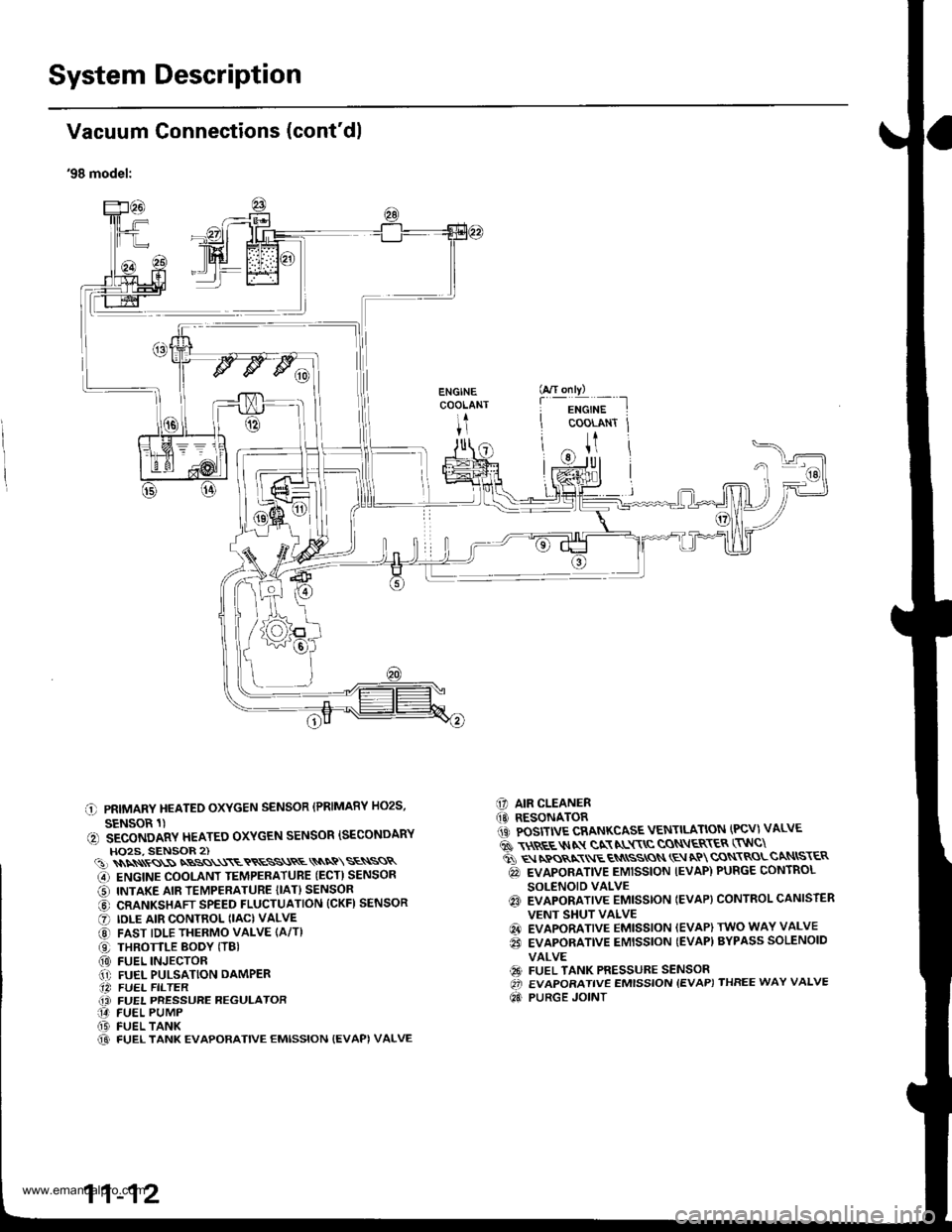
'98 model:
C PRIMARY HEATEO OXYGEN SENSOR (PRIMARY HO2S,
SENSOR 1)(, SECONDARY HEATEO OXYGEN SENSOR ISECONDARYHO2S, SENSOR 2)(!)\\\\ss\SNBSS\\\ETRESS\RE\\NQ\SE\SSR
G) ENGINE COOLANT TEMPERATUBE (ECT) SENSOR
O INTAKE AIR TEMPERATURE {IAT} SENSOR
@ CRANKSHAFT SPEED FLUCTUATION (CKFI SENSOR
O IDLE AIR CONTROL (IAC) VALVE
@ FAST IDLE THERMO VALVE (A/T)
O THROTTLE BODY (TBI(0) FUEL INJECTOR.1' FUEL PULSATION DAMPER.14 FUEL FILTER(i FUEL PRESSURE REGULATOR14 FUEL PUMP(D FUEL TANK@ FUEL TANK EVAPORATIVE EMISSION {EVAPI VALVE
C] AIR CLEANER(O RESONATOR1iC POSITIVE CRANKCASE VENTILATION (PCV) VALVE
6 \$REE$IN gN NL$\C CON\ER\ER (TNC\
ti q rpos,xr E qN
ssros \E aP cqN\RoLcaNtsr€R
@ EVAPORATIVE EMISSION IEVAP) PURGE CONTROL
SOLENOID VALVEq3 EVAPORATIVE EMISSTON IEVAP} CONTROL CANISTER
VENT SHUT VALVE
@ EVAPORATIVE EMISSION (EVAP) TWO WAY VALVE
€i EVAPORATIVE EMISSION {EVAP) BYPASS SOLENOID
VALVE
€9 FUEL TANK PRESSURE SENSOROi EVAPORATIVE EMISSION {EVAP) THREE WAY VALVE
Qd PURGE JOINT
G/T only)
f
-i*'";-t
COOLANT Jt
U
11-12
www.emanualpro.com