Page 144 of 1395

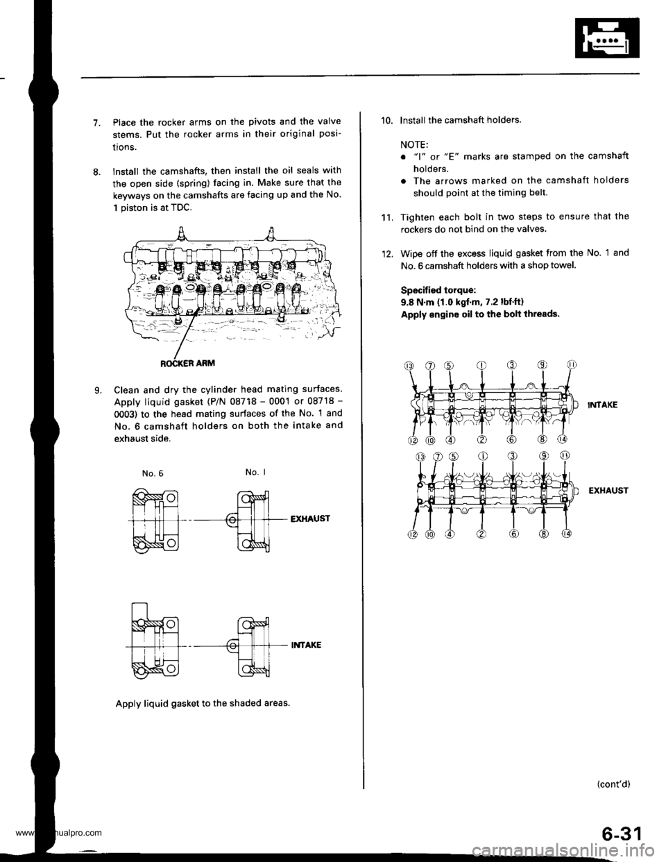
7.Place the rocker arms on the pivots and the valve
stems. Put the rocker arms in their original posi-
lrons.
lnstall the camshafts, then install the oil seals with
the open side (spring) facing in. Make sure that the
keyways on the camshafts are facing up and the No.
1 piston is at TDC.
Clean and dry the cylinder head mating surfaces.
Apply liquid gasket (P/N 08718 - 0001 or 08718 -
0OO3) to the head mating surfaces of the No. 1 and
No. 6 camshaft holders on both the intake and
exhaust side.
L
No. I
EXHAUST
II{TAKE
Apply liquid gasket to th€ shaded areas.
't't,
'10. lnstall the camshaft holders.
NOTE:
o "1" or "E' marks are stamped on the camshaft
holders.
. The arrows marked on the camshaft holders
should point at the timing belt.
Tighten each bolt in two steps to ensure that the
rockers do not bind on the valves.
Wipe off the excess liquid gasket from the No. 1 and
No. 6 camshaft holders with a shop towel,
Specified torque:
9.8 N.m (1.0 kgf.m, 7.2 lbf.ft)
Apply engine oil to the bolt ihreads.
I?,ITAKE
EXHAUST
(cont'd)
6-31
www.emanualpro.com
Page 145 of 1395

Cylinder Head
Installation (cont'dl
'13. Align the marks on the cylinder head plug to thecylinder head upper surface, then install the cylin
der head plug in the end of the cylinder head.
CYLINOER HEADPLUGReplace.
lnstallthe back cover.
To set the camshafts at TDC position for the No. lpiston, align the holes in the camshafts with theholes in the No. l camshaft holders and insert 5.0mm pin punches in the holes. Install the keys into
the camshaft grooves.
37 N m (3.8 *gl.m, 27 lbt.tr)
9.8 N.m (1.0 kgtm,7.2|hrftl
Push the camshaft pulleys onto the camshafts. thentighten the retaining bolts to the torque specified.
6-32
14.
KEYS
I x 1.25 mm
6x1.0mm
Install the timing belt (see page 6-1 1).
Adjust the valve clearance (see page 6-3).
Thoroughly clean the head cover gasket and thegroove.
lnstall the head cover gasket in the groove of thecylinder head cover. Seat the head cover gasket in
the recesses for the camshaft first, then work it into
the groove around the outside edges. Make sure thehead cover gasket is seated securely in the corners
of the recesses with no gap.
17.
'18.
19.
www.emanualpro.com
Page 146 of 1395

21.
22.
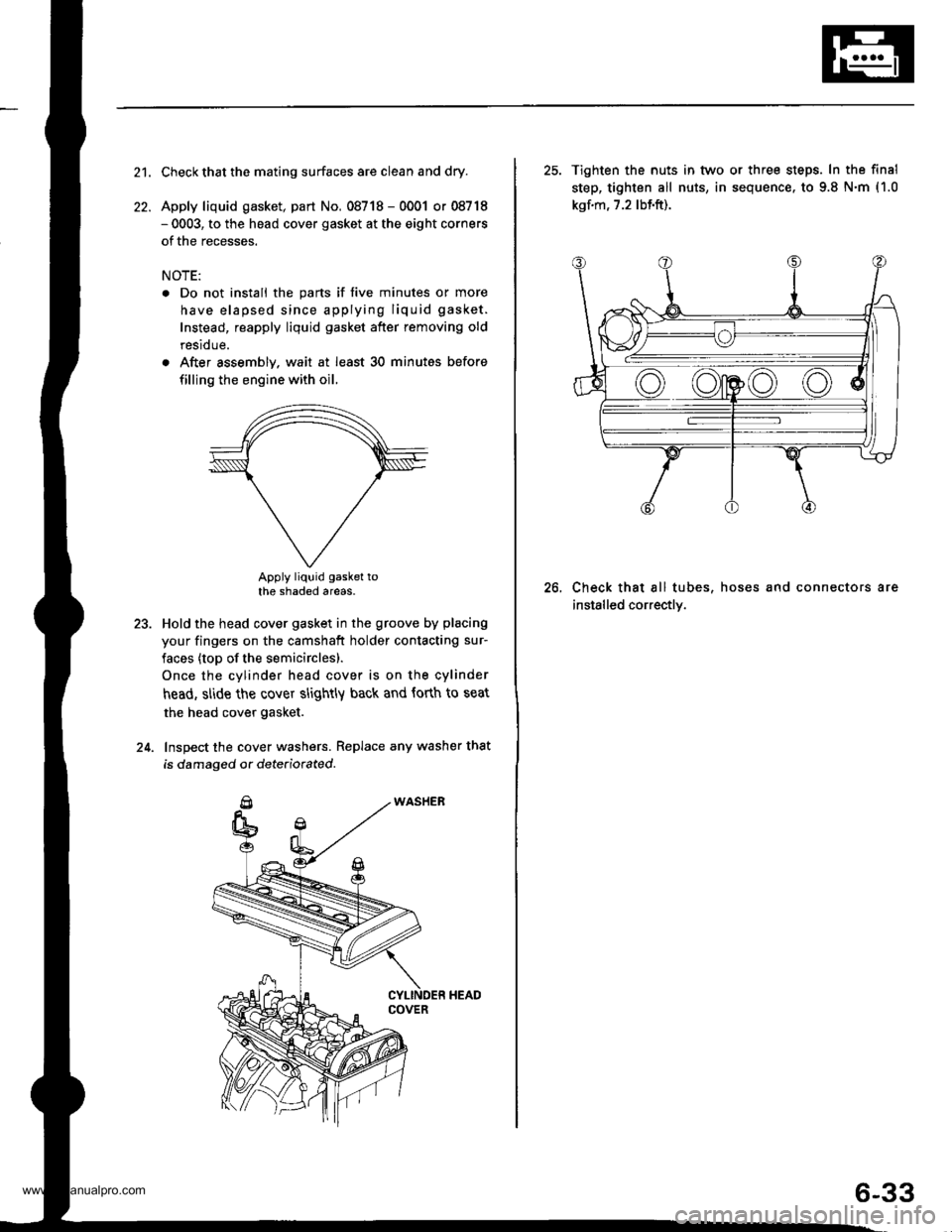
Check that the mating surfaces are clean and dry.
Apply liquid gasket, part No. 08718 - 0001 or 08718- 0003, to the head cover gasket at the eight corners
of the recesses.
NOTE:
. Do not install the parts if five minutes or more
have elapsed since applying liquid gasket.
Instead, reapply liquid gasket after removing old
residue.
. After assembly. wait at least 30 minutes before
filling the engine with oil.
Apply liquid gasket tothe shaded areas.
Hold the head cover gasket in the groove by placing
your fingers on the camshaft holder contacting sur-
faces (top of the semicirclesl.
Once the cylinder head cover is on the cylinder
head, slide the cover slightly back and forth to seat
the head cover gasket.
Inspect the cover washers. Replace any washer that
is damaged or dete(iorated.
23.
24.
25. Tighten the nuts in tvvo or three steps. In the final
step, tighten all nuts, in sequence. to 9.8 N.m (1.0
kgf.m, 7.2 lbf.ft).
Check that all tubes, hoses and connectors are
installed correctly.
26.
6-33
www.emanualpro.com
Page 432 of 1395
Glutch Master Cylinder
Removal/lnstallation
CAUTION:
. Do not spill brake fluid on the vehicle; it may damage
the paint; if brake tluid does contact the paint. wash
it off immediately with water.
. Plug the end ol the clutch line and leservoir hose
with a shop towel to prevent brake tluid trom coming
out.
The brake fluid may be sucked out through the top
of the master cylinder reservoir with a syringe.
Disconnect the clutch line and reservoir hose from
the clutch master cylinder,
't.
9.8 N.m 11.0 kst m,7.2 tbf.ftl
CLUTCH LINE
19 N'm 11 9 kgJ m'
14 lbf.frl
Remove the reservoir from the engine compartment
bulkhead.
13 N.m t1.3 kgt.m,g.il lbtft)
4. Prv out the lock pin, and pull the pedal pin out of
the voke. Remove the nuts.
NUTSI x 1.25 mm
5, Remove the clutch master cylinder.
CLUTCH MASTERCYLINDEF
Install the clutch master cylinder in the reverse
order of removal.
NOTE: Bleed the clutch hydraulic system {see page
12-61.
12-5
www.emanualpro.com
Page 937 of 1395

Master Cylinder/Brake Booster
Removal/lnstallation
1, Disconnect the brake fluid level switch connectors.
2. Remove the reservoir cap from the master cylinder.
3. Remove the brake fluid from the master cvlinder
reservoir with a syringe.
4. Disconnect the brake lines from the master cylinder.
To prevent spills, cover the line joints with rags or
shop towels.
5. Remove the master cylinder mounting nuts and
wasners.
6. Remove the master cylinder from the brake booster.
CAUTION: Be careful not to bend or damage the
brake lines when removing the master cylinder.
Do not spill brake fluid on the vehicle; it may dam.
age the paint; it brake fluid does cont.ct the paint,
wash it oft immediately with water.
7. Disconnect the vacuum hose from the brake booster.
8. Remove the cotter pin and clevis pin from the clevis.
Do not disconnect the clevis by removing it from
the operating rod of the brake booster. lf the clevis
is loosened, adjust the pushrod length before
installing the brake booster (see page 19-15).
To Front Caliper (Without ABS)
\\
15 N.m {1.5 kgtm, vAcuuM HosE
r r rbf.ft) |
/ | BRAKE FLUTD LEvEL
/l /
swrrcHcoNNEcroRs
/ I I I COTTER PIN
I I / neotace
l,/-- ro Rear wheet cylinders / | I
h ./-''' /. I I IYli //*s (.S
I /r:
9. Remove the four booster mounting nuts.'10. Pull the brake booster forward until the clevis is
clear of the bulkhead.
11. Remove the brake booster from the enqine com-
panment.
12. Install the brake booster and master cylinder in the
reverse order of removal, and note these items:
. When connecting the brake lines, make sure that
there is no interference between the brake lines
and other parts.
. Be careful not to bend or damage the brake lines
when installing the master cylinder.
. lf replacing the master cylinder or brake booster,
check and adjust the pushrod clearance before
installing the master cylinder (see page 19-14).
Fill the master cylinder reservoir, and bleed the
brake system (see page 19-7).
After installation, check the brake pedal height and
brake pedal free play (see page 19-5), and adjust if
necessary.
13 N.m 11.3 kg{.m,I rbf.ft)
13.
14.
To Master Cylinder(Without ABS)To Modulator Unit(with ABs)@-\
\
^ To Front Caliper
9i\.
-#qCLEVIS PIN
):-,/
PROPORTIONING CONTROL VALVE
MASTER CYLINDER
15 N.m (1.5 kgf.m, 11 lbl.ftl
BRAXE BOOSTER
www.emanualpro.com
Page:
< prev 1-8 9-16 17-24