1997 HONDA CR-V Ignition system
[x] Cancel search: Ignition systemPage 288 of 1395

PGM-FI System
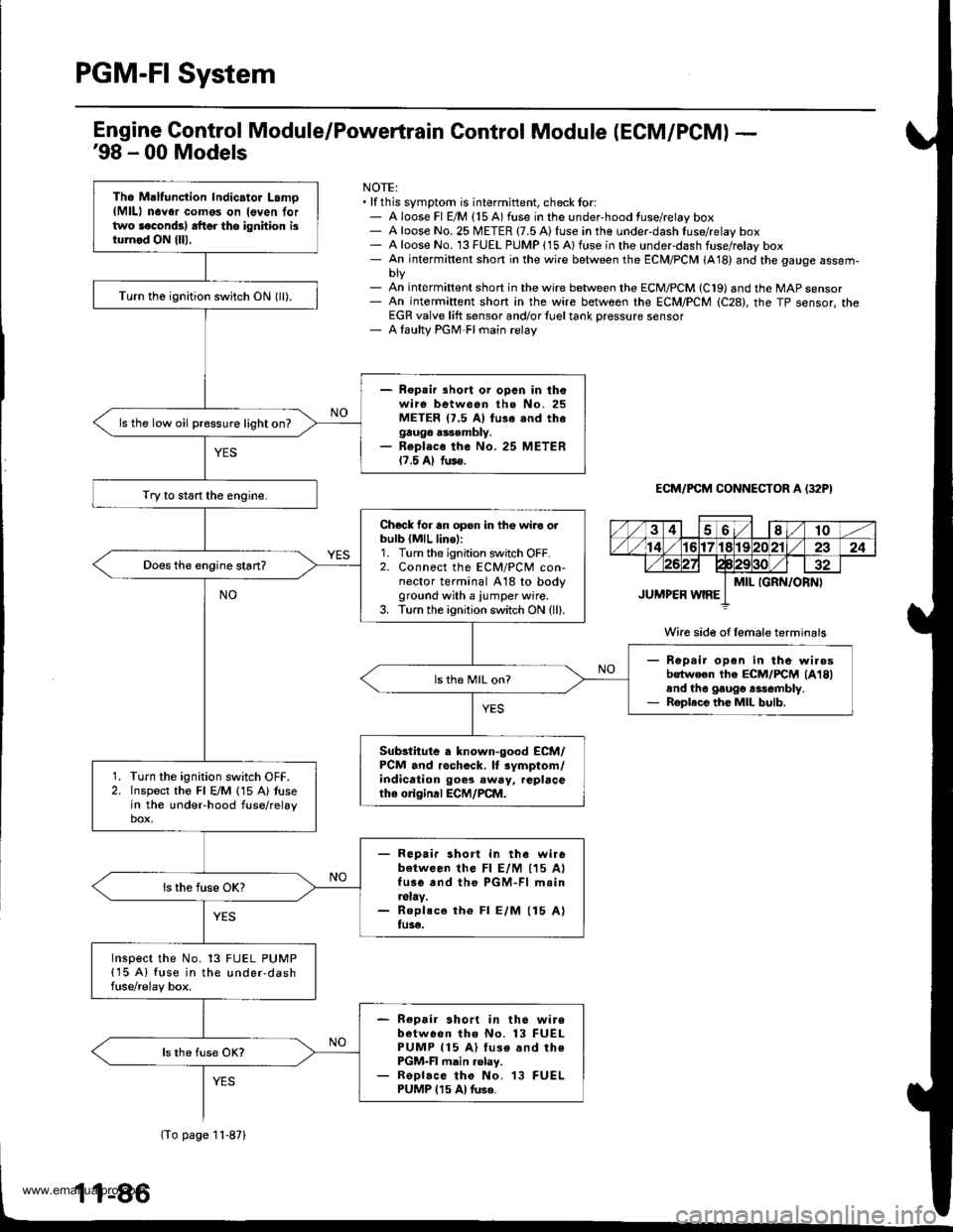
Tho Maltunction Indicator Lamo(MlL) n6Yor como3 on leven lortwo laconds) rft6r tho ignhion isturnod ON {lll.
Turn th6 ignition switch ON (ll).
- Repair lhort or opcn in thowire between the No. 25METER 17.5 Al fu3e snd thegauge assembly.- Repl.co the No. 25 METER17.5 Al fus€.
ls the low oil pressure light on?
Try to start the engine.
Chock for an opsn in th€ wiro orbulb {MlL line,:1. Turn the ignition switch OFF.2. Connect the ECM/PCM con-nector terminal A18 to bodyground with a iumper wire.3. Turn the ignition switch ON (ll).
Rep.ir open in the wi.osbotween the ECM/FCM lA18land the gaugo rasombly.Roplece the MIL bulb.
ls th6 MIL on?
Substitute a known-good ECM/PCM and rochock. lf rymptom/indication goes eway, replacetho o gind ECM/PCM.
Turn the ignition switch OFF.Inspect the Fl E/M 115 A) tusein the undeFhood fuse/relaybox.
- Repair short in the wirebetween lhe Fl E/M (15 AlfusG and the PGM-Fl m.in.slay.- Roplsce th€ Fl E/M (15 Alfu3€.
Inspect the No. 13 FUEL PUMP(15 A) fuse in the under-dashfuse/relay box.
- Repair short in th6 wirebetween tho No. 13 FUELPUMP 115 A) luse and thePGM-FI main .elay.- ReDlace tho No. 13 FUELPUMP 115 Al tuse.
Engine Gontrol Module/Powertrain Control Module (ECM/PCM) -'98 - 00 Models
NOTE:. lf this symptom is intermittent, check tor:- A loose Fl E/M {15 A) fuse in the under-hood fuse/relay box- A loose No. 25 METER {7.5 A) fuse in the under-dash fuse/relay box- A loose No. 13 FUEL PUMP (15 Alfuse in the underdash fuse/rolay box- An intermiftent short in the wire between the ECM/PCM (A18) and the gauge assem-
- An int€rmiftent short in the wire between the ECM/PCM (C19) and the MAP sensor- An intermiftent short in the wire between rhe ECM/PCM (C28), the TP sensor, theEGR valve lift sensor and/or {uel tank Dressure sensor- A laulty PGM-FI main relay
ECM/PCM CONNECTOR A (32P}
Wire side of female terminals
(To page 11-871
www.emanualpro.com
Page 290 of 1395

PGM-FI System
Engine Control Module/Poweftrain Control Module (ECM/PCM) -'98 - 00 Models (cont'dl
NOTE:. When there is no Diagnostic Trouble Code IDTC) stored, the MIL will stay on iI the SCSservice connector is connected and the ignition switch is ON (ll).. lf this symptom is intermittent, check for:- An intermittent short in the wire between the ECM/PCM (A10) and the service checkconnoctor- An intermittent short in the wire between the ECM/PCM (At8l and the gaugeassemDty. See the OgD ll scan tool or Honda PGM Tester user's manuals for specific operatingrnstructions.
ECM/FCM CONNECTOF A {32P)
Wire side of femsle t6rminals
The Malfunction lndicator LamolMlll 3lays on or comes on aftertwo 3econds.
Check the Dirgnostic TroubloCod€ (DTCI:'1. Connect a scan tool or HondaPGM Tester.2. Turn the ignition switch ON (ll).3. Read the DTC with the scantool or Honda PGM Tester.
Go to troublGhooting procadura.(3€c prg€ l lS0l
check tho DTc by MIL indication:1. Turn the ignition switch OFF.2. Connect the SCS service con-nector to the service checkconnector,3. Turn the ignition switch ON (ll).
Ropair op.n ol Bhort in wirob.twe.n thc ECM/FCtrl (A21)
and D.i. Link Connoctor.Go to troublo3hootlng proc€-dur6. lt o pag. 11.6lrl
Does the MIL indicate any DTC?
Try to start the engine.
Sub3titute r known"good ECM/PCM .nd roch.ck. lt .ymptom/indic.tion gooa awsy, repl.cothe origin.l ECM/PCM.
Does the engine stan?
Check tor a 3hort in the wireISCS linel:1. Turn the ignition switch OFFand turn the ignition switchoN { ).2- Measure voltage betweenbody ground and the ECM/PCi, conneclor terminal A10.
Ropria ahort to body ground intho wi.c Mwe.n tho ECM/PCMlA10l and aarvic. check connsc-tor.
lTo page 1l-89)
11-88
www.emanualpro.com
Page 292 of 1395

PGM-FI System
Manifold Absolute Pressure (MAPI Sensor
The scan tool indicates Diagnostic Trouble Code (DTC) POl07: A low input (high vacuum) problem in theManifold Absolute Pressure (MAP) sensor,
The MAP sensor convens manifold absolute pressure into electrical signals and inputs the ECM/pCM.
OUTPUIVOLTAGE
tvl3.s
3.0
2.5
2.O
1.5
1.0
0.5
o .5 ro- 15^ 1olin.H9) GAUGEREADIT{G
lmmHgl
3025
100 200 300 a00 5oo 6fi, 7d)
MAP SENSOR 3P CONNECTOR IC131I
vccl(YEL/RED}
Th6 MIL has b€en reoorted on.DTC P0107 is 3tored.
Problom verification:1. Turn the ignition switch ON lll).2. Check the lvlAP with the scanroot.
lrtormittem tailu.e, lystam b OKat thb timo. Check tor poor con-noctions or loosa wird at C131(MAP rensor) and rt the ECM/PCM.
ls approx. 101 kPa (760 mmHg,30 in.Hg),2.9 V indicated?
Check for an op6n in wi.o IVCC1linel:1. Turn the ignition switch OFF.2. Disconnect the MAP sensorconnector,3. Turn the ignition switch ON {ll}.4. Measure voltage between theMAP sensor connector No. 1termanal and No. 2 terminal.
Roprir op€n in the wir6 bstweentho ECM/PCM (D4, C19*l and theMAP sensor.
ls there approx. 5 V?
(To page 11-91)
11-90
Wiro side ol temale terminals
www.emanualpro.com
Page 294 of 1395
![HONDA CR-V 1997 RD1-RD3 / 1.G Workshop Manual
PGM-FI System
Manifold Absolute Pressure (MAP) Sensor (contd)
[tn,t nn-] The scan tool indicates Diagnostic Trouble Code (DTC) P0108: A high voltage (low vacuum) problem in the|jg Manifold Absolute HONDA CR-V 1997 RD1-RD3 / 1.G Workshop Manual
PGM-FI System
Manifold Absolute Pressure (MAP) Sensor (contd)
[tn,t nn-] The scan tool indicates Diagnostic Trouble Code (DTC) P0108: A high voltage (low vacuum) problem in the|jg Manifold Absolute](/manual-img/13/5778/w960_5778-293.png)
PGM-FI System
Manifold Absolute Pressure (MAP) Sensor (cont'd)
[tn,t nn-] The scan tool indicates Diagnostic Trouble Code (DTC) P0108: A high voltage (low vacuum) problem in the|jg Manifold Absolute Pressure (MAP) sensor.
MAP SENSOR 3P CONNECTOR IC131I
Wire side of female terminals
vcclIYEL/RED}
PCM CONNECTOR D I16PI
JUMPER WIRE
sGlIGRN/WHTI
Wire side of lemale termin6ls
1
(To page 11,93)': '98 - 00 models
1-92
tcRN/wHrll IIRED/GRN|
The MIL has boen reported on.DTC m108 is slored.
Problem veritication:1. Start the engine. Hold theengine at 3,000 rpm with noload (in Park or neutral) untilthe radiator fan comes on, thenlet it idle.2. Check the MAP with the scantool.
Intermittent tailuro, system i3 OKat this time. Check tor ooor con-nections or loose wires at C131IMAP s6nsor) snd the ECM/rcM.
ls 101 kPa {760 mmHg,30 in.Hg),2.9 V or higher indicated?
Check Ior an open in the MAPsensor:1. Turn the ignition switch OFF.2. Disconnect the MAP sensor3P connector.3. lnstall a jumper wire betweenthe MAP sensor 3P connectorterminals No.3 and No.2.4. Turn the ignition switch ON {ll).5. Check the MAP with the scantool.
ls 10'l kPa (760 mmHg,30 in.Hg),2.9 V or higher indicated?
Check for an open in wire (SGlliDel:1. Remove the jumper wire.2. Measure voltage between theMAP sensor 3P connector ter-minals No. 1 and No- 2.
R6p.ir open in the wire betwoenthe ECM/PCM (D12, CTrl and theMAP sensor.
ls there approx. 5 V?
Check for an open in the wire(MAP line):1. Turn the ignition switch OFF.2. lnstall a iumper wire on thePCM connectors between D3and D12.3. Turn the ignition switch ON (ll).4. Check the MAP wirh the scantool.
Ropair opon in the wire betweenthe PCM {D3, .nd the MAP son-3('t.
ls 101 kPa 1760 mmHg, 30 in.Hg),2.9 V or higher indicated?
YES
www.emanualpro.com
Page 296 of 1395

PGM-FI System
Manifold Absolute Pressure (MAP) Sensor (cont'dl
The scan tool indicates Diagnostic Trouble Code (DTC) P1128: Manifold Absolute pressure (MAp) lower thanexoected.
The scan tool indicates Diagnostic Trouble Code (DTC) P'l129: Manifold Absolute Pressure (MAP) higher thanexpected.
l
- The MIL has be6n r€ported on.- DTC Pl128 is stored.
Problom verification:1. Turn the ignition switch ON 1lli.2. Check the MAP with the scantool,
ls 54.1 kPa (406 mmHg, 16.0 in.Hg),1.61 V or higher indicated?I to.mittent failure, 3ydom i! OKal thbtimc,
- The MIL has boen reportod on.- DTC Pl129 is stored.
Problem veritication:1. Start the engine. Hold theengine at 3,000 rpm with noload lin Park or neutral) untilthe radiator fan comes on,then Iet it idle.2. Check the MAP with the scantool,
ls 43.3 kPa (325 mmHg, 12.8 in.Hg),'1.32 V or less indicated?Intarmittani fuilure, systom i3 OKat this time.
11-94
www.emanualpro.com
Page 298 of 1395

PGM-FI System
Intake Air Temperature (lAT) Sensor (cont'dl
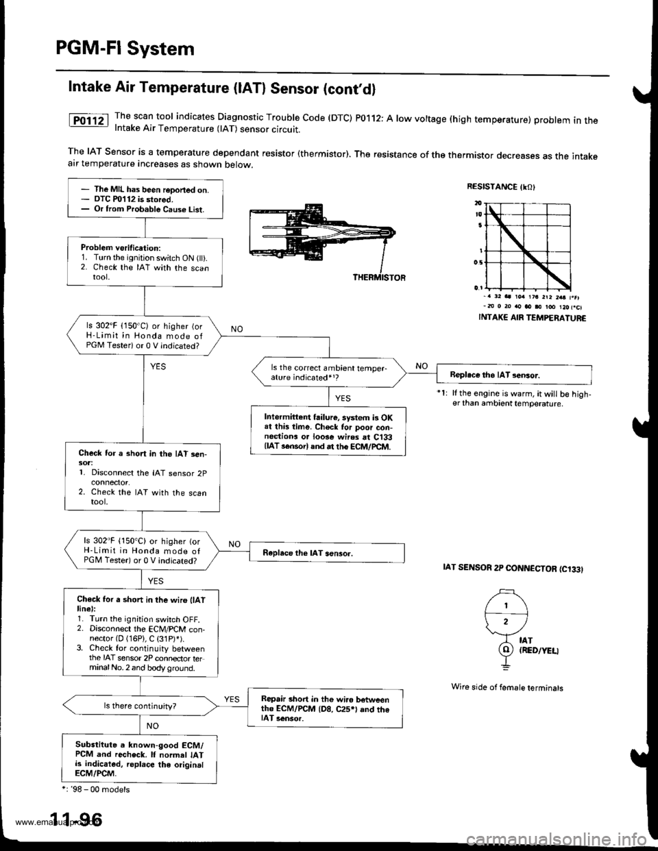
The scan tool indicates Diagnostic Trouble code (DTC) P0112: A low voltage (high temperature) problem in theIntake Air Temperature 0AT) sensor circuit.
The IAT Sensor is a temperature dependant resistor (thermistor). The resistance of tho thermistor decreases as the intakeair temperature increases as shown below.
RESISTANCE IKO)
i')
)2 /
A tAr
9) (RED/YEU
-L
-. 32 aa rorr 1?a 2ra 2aa f.el-m 0 20 rto ao i0 too l2ofcl
INTAKE AIR TEMPERATUR€
It the engine is warm, it will b€ high-er than ambient temperature.
IAT SENSOR 2P CONNCCTOR (C'33I
- The MIL has been reDoned on.- OTC m112 is stored,- Or from Probable Caus€ List.
Problem vsrification:1. Turn the ignition switch ON flt).2. Check the IAT with the scantool.
ls 302'F (150'C) or higher (orH-Limit in Honda mode ofPGM Testeri or 0 V indicated?
ls the correct ambient temper-ature indicated,,?Beploce tho IAT sensor.
Intermittent failure, system i3 OKat this time. Ch6ck for poor con-nectiona o. loose wires rt C133{lAT s€nsorl and rt th6 ECM/pCtr4.Check for a short in the IAT sen-sot:1. Disconnect the IAT sensor 2p
2. Check the IAT with the scantool.
ls 302"F {150"C) or higher {orH-Limit in Honda mode ofPGM Tester) or 0 V indicated?Raplace the lAT aensor.
Ch€ck for a short in the wir6 llAtlinel:1. Turn the ignition switch OFF.2. Disconnect the ECM/PCM con-nector {D (16P}, C (31P)').3. Check for continuity betweenthe IAT sensor 2P connector terminalNo.2 and body ground.
Repair short in the wi.o botweenth6 ECM/rcM {D8, C25*l and th6IAT 3ensor.
Substitute a known-good ECM/PCM and recheck. lf normel IATis indicaled, replace the originalECM/PCM,
*: '98 - 00 models
1 1-96
Wi16 side of femsle terminals
www.emanualpro.com
Page 300 of 1395

PGM-FI System
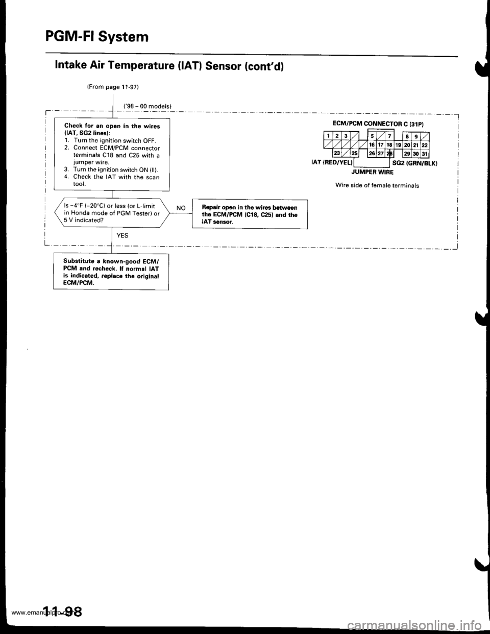
Check for an open in the wires{lAT, SG2lines):1. Turn the ignition switch OFF.2. Connect ECM/PCM connectorterminals C18 and C25 with ajumper wire.3. Turn the ignition switch ON (ll).4. Check the IAT with the scantool.
ls -4'F 1-20"C) or less (or L limitin Honda mode of PGM Testeri or5 V indicated?
Repsir op€n in the wirca batweenthe ECM/PCM 1C18, C25l and theIAT s€nsor.
Substitute a known-good ECM/PCM rnd recheck, lf normal IATis indicated, leplaco the originslECM/PCM.
Intake Air Temperature (lATl Sensor (cont'd)
(From page 11,97)
'l
ECM/PCM CINNECTOR C t3lPl
257II
./ 16171819 202122234 Wp,29c)31
sG2IAT {RED/YELI{GRN/BLK)
JUMPER WIRE
Wire side of fernale terminals
I
1 1-98
www.emanualpro.com
Page 302 of 1395

PGM-FI System
Engine Coolant Temperature (ECTI Sensor {cont'd)
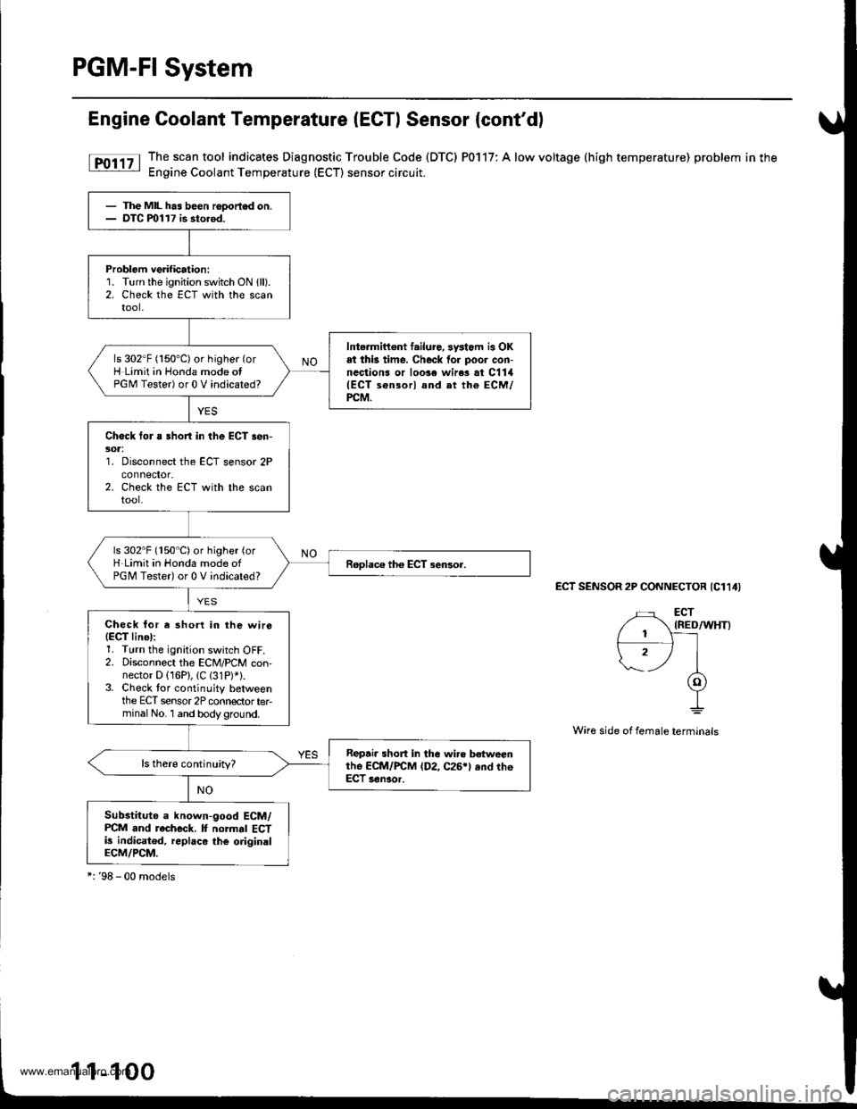
[F011' The.scan tool indicates Diagnostic Trouble Code (DTC) P0117: A low voltage (high temperature) problem in the: Engine Coolant Temperature (ECT) sensor circuit.
ECT SENSOR 2P CONNECTOR {C114I
Wire side of female terminals
- The MIL has been rooortod on.- DTC ml17 is sto.od.
Problem verification:1. Turn the ignition switch ON {ll).2. Check the ECT with the scantool,
Intermittont f.ilure, sysiom is OKat thk time. Check for poor con-nections or loo3e wire3 at C1lil(ECT sensorl and et the ECM/PCM.
ls 302"F (150'C) or higher (or
H Limit in Honda mode otPGM Tester) or 0 V indicated?
Check for a Bhort in the ECT sen-301:'1. Disconnect the ECT sensor 2Pconnefior,2. Check the ECT with the scantool.
ls 302"F (150"C)or higher (or
H-Limit in Honda mode ofPGM Tester) or 0 V indicated?
Check for r shorl in the wirs(EgT linel:1. Turn the ignition switch OFF.2. Disconnect the ECM/PCM con-nector D (16P), (C (31P)*1.3. Check tor continuity betweenthe ECT sensor 2P connectorterminal No. 1 and bodyground.
Repair short in the wir€ betweenthe ECM/FCM (D2, C26rl ,nd th6ECT senaor.
ls there continuity?
Substitute a known-good ECM/PCM and recheck. It normal ECTi! indicatod, replaco the oiiginalECM/PCM.
*:'98 - 00 models
1-1
www.emanualpro.com