1997 HONDA CR-V voltage
[x] Cancel search: voltagePage 1314 of 1395
Description
J)
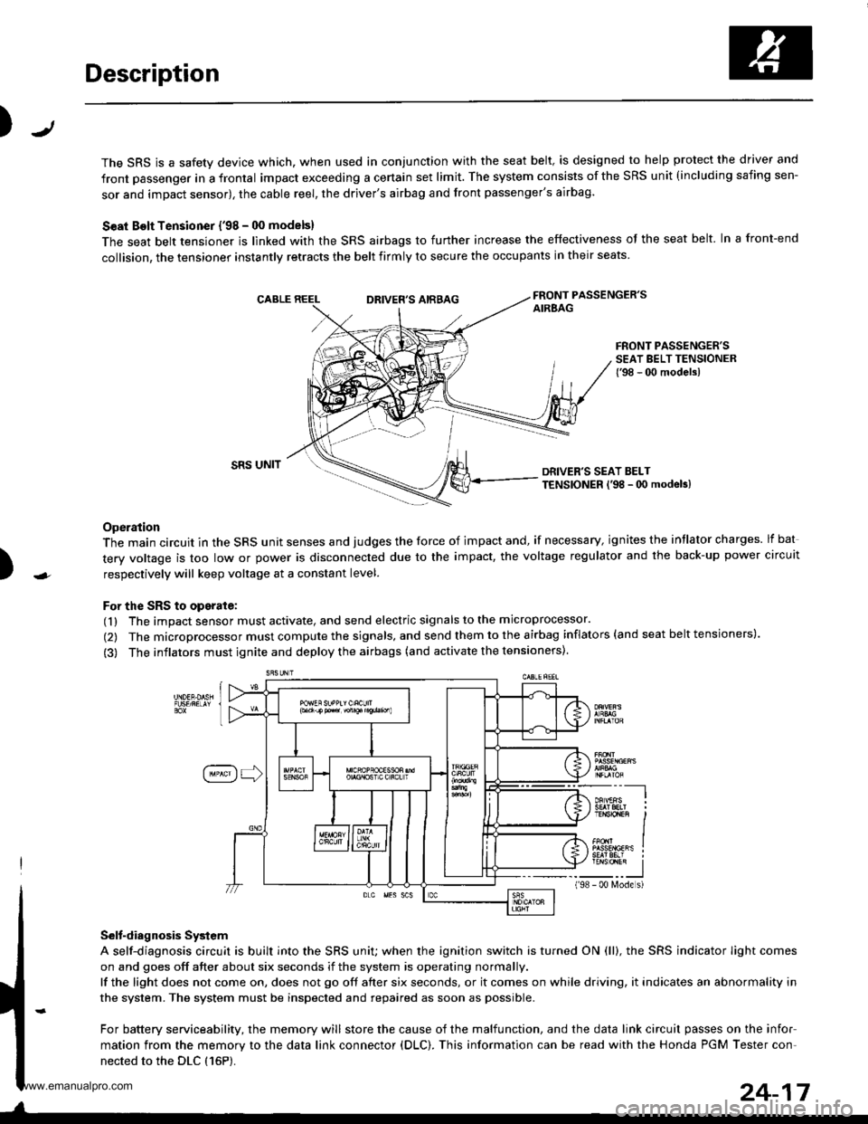
The SRS is a safety device which, when used in conjunction with the seat belt, is designed to help protect the driver and
front passenger in a frontal impact exceeding a certain set limit. The system consists of the SRS unit (including safing sen-
sor and impact sensor), the cable reel, the driver's airbag and front passenger's airbag.
Seat Bolt Tensioner {'98 - 00 models}
The seat belt tensioner is linked with the SRS airbags to further increase the effectiveness of the seat belt. In a front-end
collision, the tensioner instantly retracts the belt firmly to secure the occupants in their seats
FRONT PASSENGER'SAIREAGDRIVER'S AIRBAG
FRONT PASSENGER'SSEAT BELT TENSIONER{'98 - 00 modelsl
)
SRS UNITDRIVER'S SEAT BELTTENSIONER l'98 - 0O modeb)
Operation
The main circuit in the SRS unit senses and judges the force of impact and, if necessary, ignites the intlator charges. lf bat
tery voltage is too low or power is disconnected due to the impact, the voltage regulator and the back-up power circuit
respectively will keep voltage at a constant level.
For the SRS to operate:
(1) The impact sensor must activate, and send electric signals to the microprocessor.
(2) The microprocessor must compute the signals, and send them to the airbag inflators (and seat belt tensioners).
(3) The inflators must ignite and deploy the airbags (and activate the tensioners).
Selt-diagnosis System
A self-diagnosis circuit is built into the SRS uniU when the ignition switch is turned ON (ll), the SRS indicator Iight comes
on and goes off after about six seconds if the system is operating normally.
lf the light does not come on, does not go off after six seconds, or it comes on while driving, it indicates an abnormality in
the system. The system must be inspected and repaired as soon as possible.
For battery serviceability, the memory will store the cause of the malfunction, and the data link circuit passes on the infor
mation from the memory to the data link connector (DLC). This information can be read with the Honda PGM Tester con-
nected to the DLC {16P).
198
---__-l
TENSTO1En II
_-___J- 00 N4ode s)
24-17
www.emanualpro.com
Page 1319 of 1395
Precautions/Procedures
Spring-loaded Lock Connectors
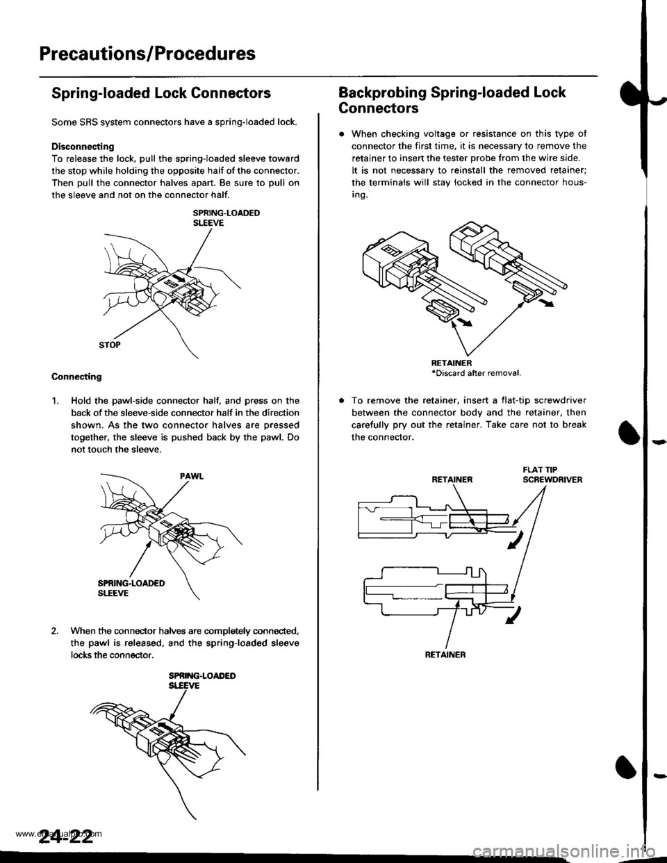
Some SRS system connectors have a spring-loaded lock.
Disconnecting
To release the lock, pull the spring-loaded sleeve toward
the stop while holding the opposite halt of the connector.
Then pull the connector halves apart. Be sure to pull on
the sleeve and not on the connector half.
SPRING-LOADEDSLEEVE
Connecting
1. Hold the pawl-side connector hall and press on the
back of the sleeve-side connector half in the direction
shown. As the two connector halves are Dressed
together, the sleeve is pushed back by the pawl. Do
not touch the sleeve.
When the connec-tor halves are completely connected,
the pawl is released. and the spring-loaded sleeve
locks the connector.
SPRING.LOAI'ED
24-22
Backprobing Spring-loaded Lock
Connectors
. When checking voltage or resistance on this type of
connector the first time, it is necessary to remove the
retainer to insert the tester probe from the wire side.
It is not necessary to reinstall the removed retainer;
the terminals will stay locked in the connector hous-
inq.
To remove the retainer, insert a tlat-tip screwdriver
between the connector body and the retainer. then
carefully pry out the retainer. Take care not to break
the connector.
RETAINER*Discard after removal.
RETAINEN
RETAINER
---
www.emanualpro.com
Page 1327 of 1395
Troubleshooting
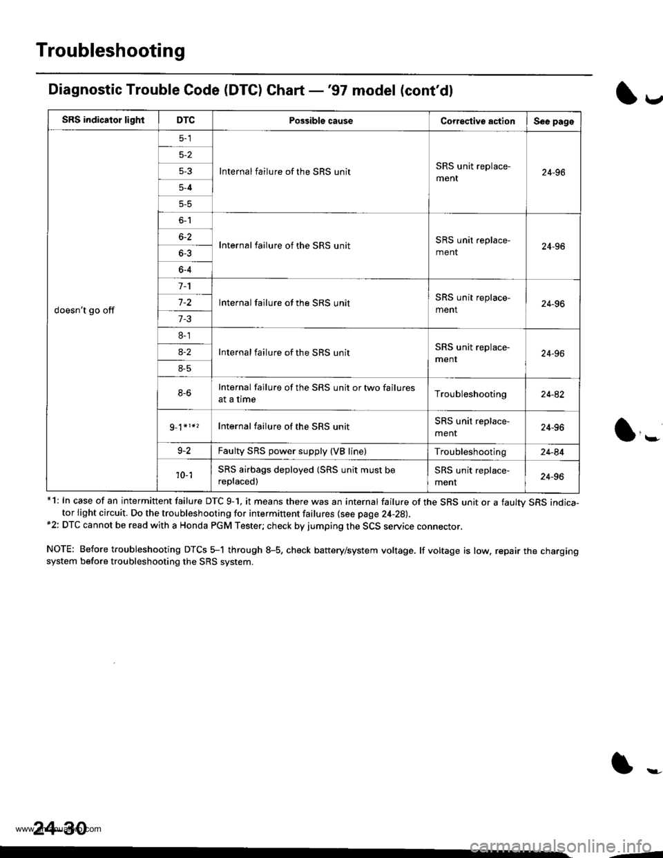
Diagnostic Trouble Code (DTC) Chart -'97 model (cont'dl
*1: In case of an intermittent failure DTC 9-1, it means there was an internal failure of the SRS unit or a faultv SRS indica-tor light circuit. Do the troubleshooting for intermittent failures {see page 24-28),*2: DTC cannot be read with a Honda PGM Tester; check by jumping the SCS service connector.
NOTE: Before troubleshooting DTCS 5-1 through 8-5, check battery/system voltage. lf voltage is low. repair the chargingsystem before troubleshooting the SRS system.
l*
SRS indicator lightDTCPossible causeCorrestive actionSee page
doesn't go off
Internal failure of the SRS unitSRS unit replace-
ment24-965-3
5-4
5-5
o-l
Internal failure of the SRS unitSRS unit replace-
ment24-966-2
6-4
lnternal failure of the SRS unitSRS unit replace-
ment24-967-2
7-3
8-1
Internal failure of the SBS unitSRS unit replace-
menr24-96a-2
8-5
8-6Internal failure of the SRS unit or two failures
at a timeTroubleshooting24-82
Internal failure of the SRS unitSRS unit replace-
menr24-96
9-2Faulty SRS power supply (VB line)Troubleshooting24-84
'10- 1SRS airbags deployed (SRS unit must be
replaced)
SRS unit replace-
ment24-96
24-30
--
www.emanualpro.com
Page 1329 of 1395
Troubleshooting
SRS indicator lightDTCPo$ibla causeCorroctive lctionSec pag€
doesn't go off
5-l
Internal failure of the SRS unitSRS unit replace-
ment24-96
5-4
6-1
lnternal failure of the SRS unitSRS unit replace-
ment24-966-3
6-4
Internal failure of the SRS unitSRS unit replace-
ment24-96
8-1
Internal failure of the SRS unitSRS unit replace-
ment24-96
8-2
8-3
8-4
8-6
Internal failure of the SRS unitSRS unit.eplace-
ment24-969_2*2*3
10- 1SRS unit replacement code (SRS unit must notbe used any longer)SRS unit replace-
ment24-96
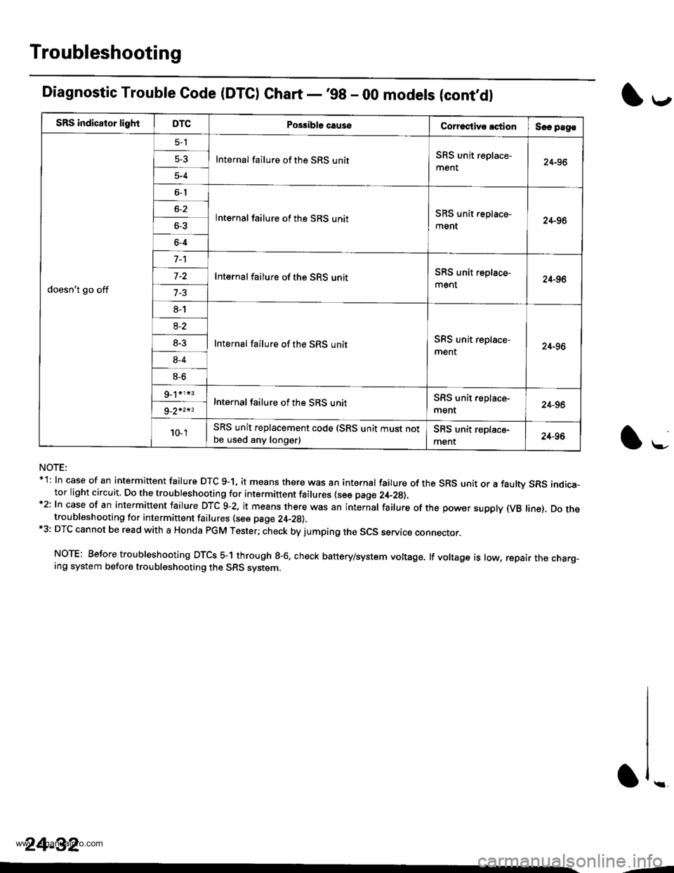
Diagnostic Trouble Code (DTC) Chart -'98 - 00 modets (cont,dl
NOTE:*1: In case of an intermittent failure DTC g-1, it means there was an internal failure of the SRS unit or a faulw SRS indica-tor light circuit. Do the troubleshooting for intermittent failures (see page 2,+_2g),*2: In case of an intermiuent fairure DTc 9-2, it means there was an internar fairure of the power suppry (vB rine). Do thetroubleshooting for intermittent failures (see page 24-29).*3: DTC cannot be read with a Honda PGM Tester; check by jumping the SCS servic€ connector.
NOTE: Before troubleshooting DTCS 5-1 through g-6. check battery/system voltage. lf voltage is low, repair the charg_ing system before troubleshooting the SRS system.
l*-
1,.-
\f ..
24-32
--
www.emanualpro.com
Page 1332 of 1395
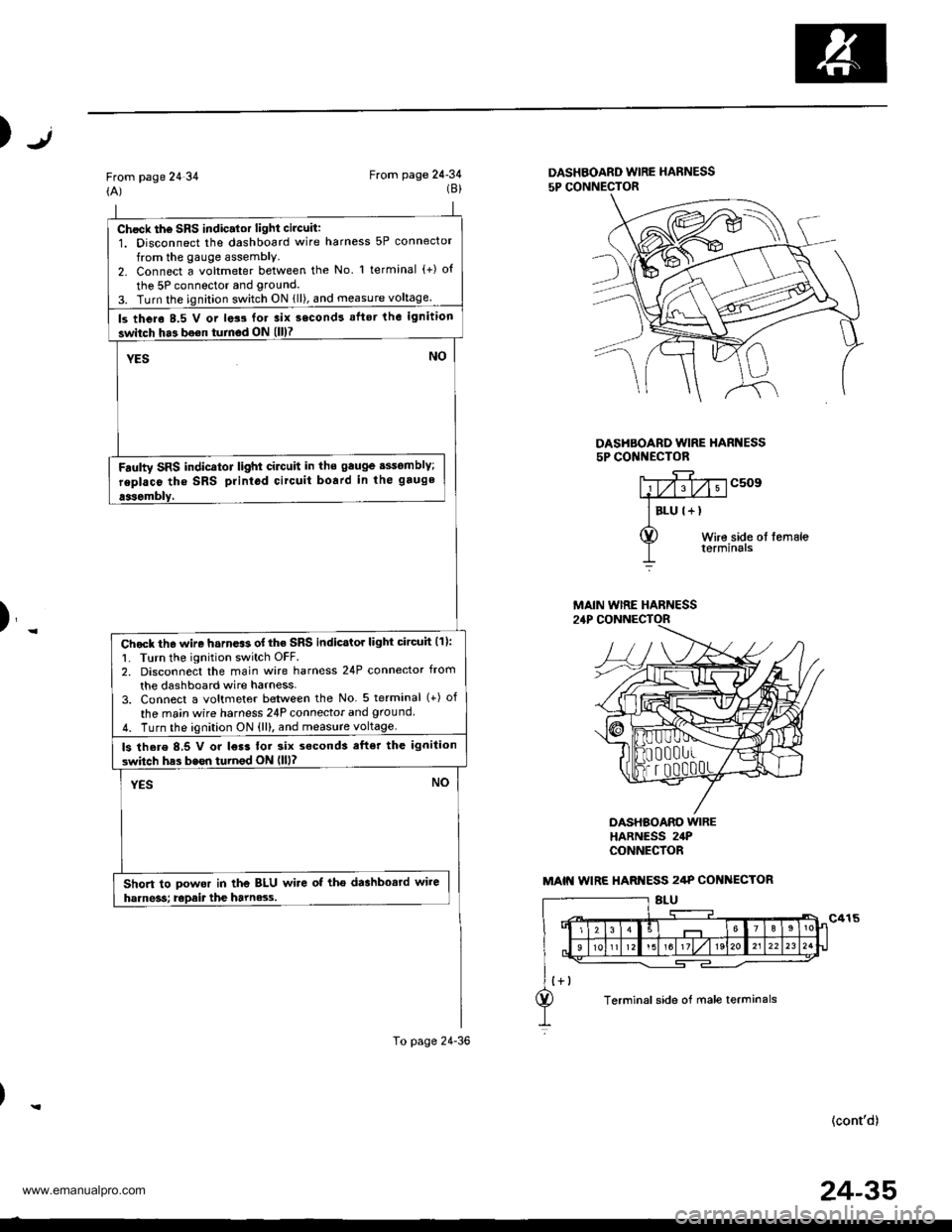
Chock th6 SRS indic.lor light circuit:1. Disconnect the dashboard wire harness 5P connector
from the gauge assembly.2. Connect a voltmeter between the No l terminal (+) o{
the 5P connector and grouncl.
3. Turn the ignition switch ON {ll), and measure voltage
ls thero 8.5 V or lats for 3ix second! aflsr the ignition
switch ha3 bo€n turnod ON (ll)7
YESNO
Fdulty SRS indicator light cilctlit in ths gauge sssomblY;
replaco tho SRS printod circuit board in the gauge
aasombly,
Chock th6 wire harn.$ of the SRS indicstor light circuh (11:
1. Turn the ignition switch OFF.2. Disconnect the main wire harness 24P connector from
the dashboard wire harness-3. Connect a voltmeter between the No 5 terminal (+) of
the ma;n wire harness 24P connecior and ground
4. Turn the ignition ON {ll), and measure voltage.
ls there 8,5 V or l€r3 tor six s€cond3 efter the ignilion
switch has bssn turnod ON llll?
YESNO
Short to powor in the BLU wire of tho dashbosrd wire
harne3s; Epait the harne3.s.
To page 24-36
Jt)
From page 24 34(A)From page 24-34(8)DASHBOARD WIRE HARNESS
5P CONNECTOR
DASHBOARD WIRE HARI{ESS5P CONI{ECTOR
c509
Wire side ol femaleterminals
)_
DASHBOARO WIREHARNESS 24PCONNECfOR
(cont'd)
MAIN WIRE HARNESS
MAIN WIRE HARI{ESS 2/tP COI{ ECTOR
Terminal side of male terminals
24-35
www.emanualpro.com
Page 1333 of 1395
Troubleshooting
From page 24-35
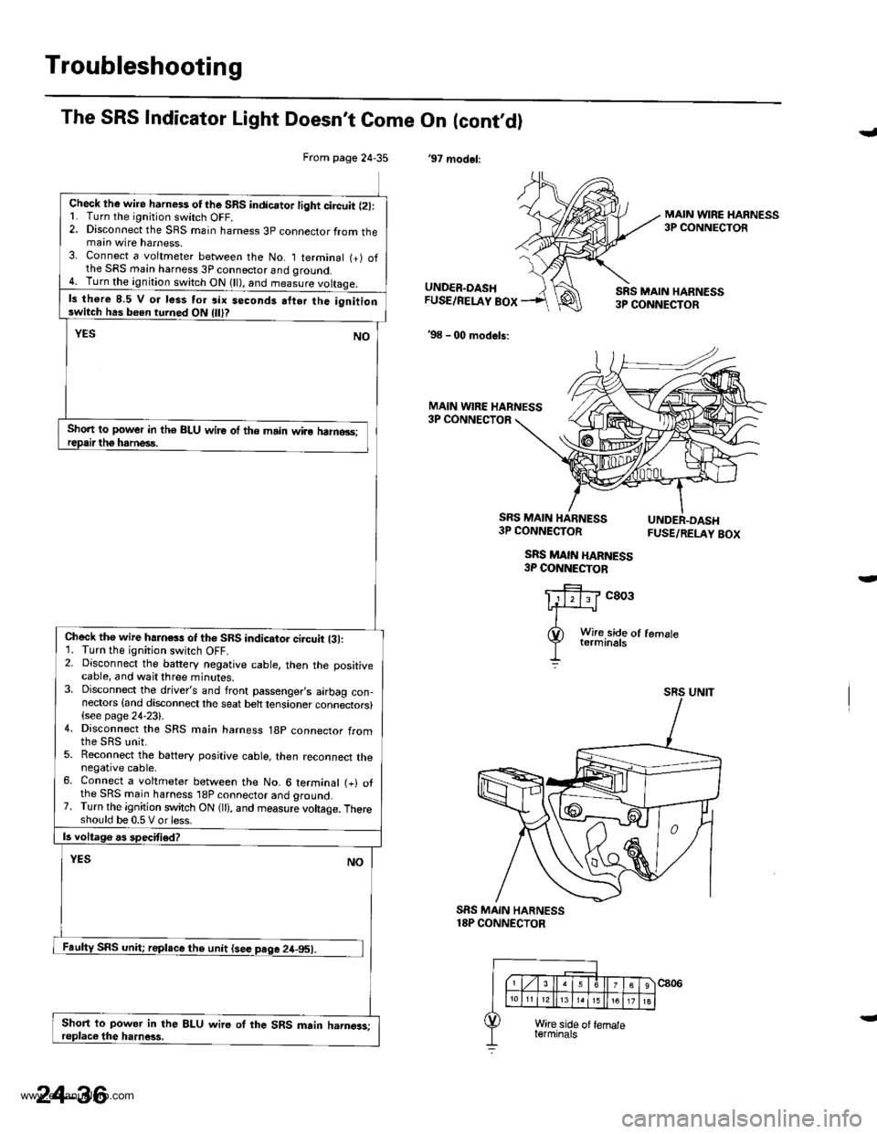
Check lhe wire harness otthe SRS indicator light circuit l2l:L Turn the ignitjon switch OFF.2. Disconnect the SRS main harness 3p connector from themain wire harness.3. Connect a voltmeter between the No. I terminal (+) ofthe SRS main harness 3P connector and qround.4. Turn the ignition switch ON (ll), and measure voltaqe.
ls there 8.5 V o. less tor six seconds atter the ignitionswitch has been turned ON
Short to power in th€ BLU wire of the main wiro halno3s;
Check th€ wire hahess of th6 SRS indicator ci.cuit {31:1. Turn the ignition switch OFF.2. Disconnect the battery negative cable, then the positivecable, and wait three minutes.3. Disconnect the driver's and front passenger,s airbag con-nectors {and disconnect the seat belt tensioner connectors}(see page 24-23).4. Disconnect the SRS main harness 18p connector from
5. Reconnect the battery positive cable, then reconnect thenegative cable.6. Connect a voltmeter between the No. 6 terminal (+) ofthe SRS main harness 'l8P connector and ground.7. Turn the ignition switch ON (ll), and measure voltage. Thereshould be 0.5 V or less.
Short to power in the BLU wire oI the SRS main harngas;
The SRS Indicator Light Doesn't Come On (cont,dl
'97 modol:
J
MAIN WIRE HARNESS3P CONNECTOR
UNDER.DASHFUSE/RELAY BOX
'98 - 00 models:
SRS MAIN HARN€SS3P CONNECTOR
MAIN WIRE HARNESS3P CONNECTOR
SRS MAIN HARNESS3P CONNECTOR
SRS MAIN HARNESS3P COI{NECTOB
FUSE/RELAY BOX
c803
SRS MAIN HARNESS18P CONNECTOR
24-36
www.emanualpro.com
Page 1334 of 1395
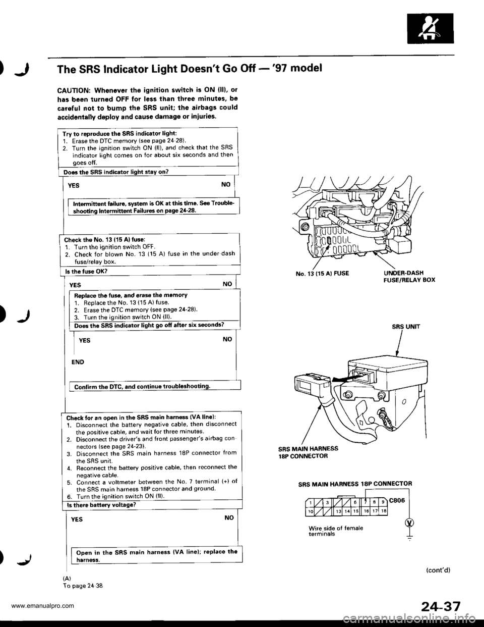
The SRS Indicator Light Doesn't Go Off -'97 model
CAUTION: Whenever th€ ignilion switch i3 ON (lll, ol
has been turn€d OFF for less than three minutes, be
careful not to bump the SRS unit; the airbags could
accidenially deploy and cause damag€ or iniuries.
Try to reproduce the sRs indicator light:
1. Erasethe DTC memory (see page 24 28)
2. Turn the ignition switch ON {ll), and check that the SRS
indicator light comes on for about six seconds and thengoes off.
Doe3 the SRS indicator light slay on?
YESNO
Intermiftent ftilure, system is OK at this time. S€o Troubl€_
shooting Intermittent Failutes on p.ge 24_28.
Check the No. 13 (15 Al fuse:'L Turn the ignition switch OFF.
2. Check for blown No. 13 (15 A) fuse in the under dash
fuse/relay box.
ls lhe tuse OK?
YESNO
Replace the luse, and err3e the memory'1. Replace the No. 13(15A)fuse2. Erase the DTc memory (see page 24-28).
3. Turn the ignition switch ON (ll).
ioes the SRS indicatol light go off after 3ix s6conds?
YESNO
ENO
Confirm tho OTC, and continue ttouble3hooting.
Check for an open in the SRS main hatn€ss {VA lins}:
1. Disconnect the batterY negative cable, then disconnect
the positive cable, and wait for three minutes.
2. Disconnect the driver's and front passenger's airbag con
nectors (see page 24-23).
3. Disconnect the SRS main harness 18P connector from
the sRs unit.4. Reconnect the battery positive cable, then reconnect the
negative cable.5. Connect a voltmeter between the No. 7 terminal (+) ot
the SRS main harness l8P connector and 9rouncl6. Turn the ignilion switch ON {ll).
ls there battory voltage?
YESNO
Ooen in the SRS main harness {VA line); replace the
natnoss.
(A)
No. 13 115 Al FUSEUNOER.DASHFUSE/RELAY BOX
)
SRS MAIN HARNESSr8P CONNECTOR
SRS MAIN HARNESS 18P CONNECTOR
(cont'd)
24-37
SRS UNIT
To page 24 38
www.emanualpro.com
Page 1338 of 1395
)
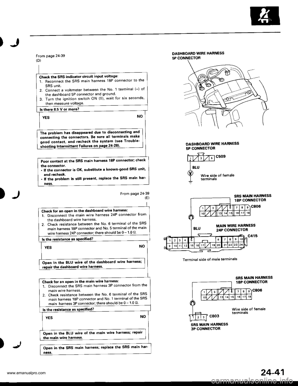
From page 24-39(D)
DASHBOARD wlRE hARNESS
5P CONNECTON
DASHBOARO WIRE HARI{ESS
5P CONI{EC'OR
)From page 24-39iE)
c509
Terminal side of male lerminals
SRS MAIN HABN€SS3P CONNECTOR
)
Check the SRS indicator circuit input voltage:
1. Reconnect the SRS main harness 18P connector to the
SRS unit2. Connect a voltmeter between the No 1 terminal (+) of
the dashboard 5P connector and ground.
3. Turn the ignition switch ON (ll), wait for six seconds,
then measure voltage
fs there 8.5 V or more? -
YESNO
The oroblem hts disappoared due to disconnocting and
connecting the connectors. Be 3ure all terminals make
good contact, and rocheck the system {see Trouble'
shooting Intermittent Failur6 on pagg 2'l-281'
Pool contacl at the SRS main harness 18P connector; check
the connector.. lf the connoctor is OK. aubstituta a known-good SRS unit,
and recheck.. ll the problem is still present, replaco the SRS main h'r-
ness.
Check for an oPen in the dashboard wire hatn8s:
1. Disconnect the main wire harness 24P connector Irom
the dashboard wire harness
2. Check resistance between the No. 6 terminal of the SRS
main hamess 18P connector and No 5 terminal otthe main
wire harness 24P connector; there should be 0- 1 0 O
15 the resistance.s specified?
YESNO
ODen in the BLU wire ot the dashboard wit6 harness;
rep.ir the dashboald wite harness.
Check for an open in the main wirc harness:'1. Disconnect the SRS main harness 3P connector from the
main wire harness,2. Check resistance between the No. 6 terminal of the SRS
main harness 18P connector and No 1 terminal ofthe SRS
main harness 3P connector;there should be 0 - 1 0 u
|3 lhe re3istance as sPecifiod?
YESNO
Oo€n in the BLU wire ol the main wire harness; rcpair
tha main wire harness
Op€n in the SRS main harn4s; replace the SRS msin har'
no3s.
24-41
www.emanualpro.com