1997 HONDA CR-V voltage
[x] Cancel search: voltagePage 1128 of 1395
Troubleshooting
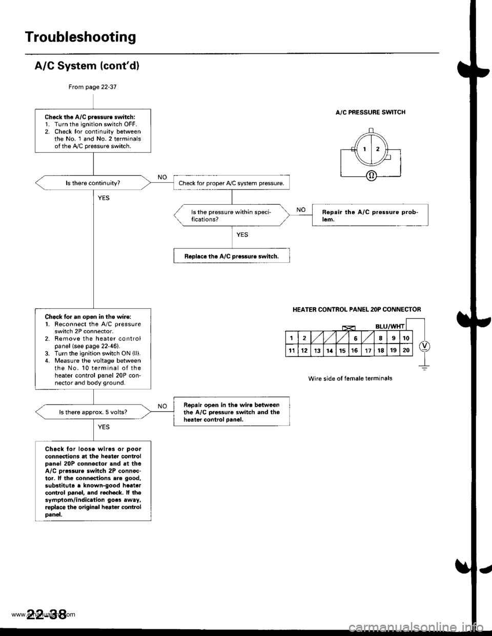
A/G System {cont'd)
From page 22-37
A/C PRESSURE SWITCHCheck th€ A/C pressure switch:1. Turn the ignition switch OFF.2. Check lor continuity bgtweenthe No. 1 and No.2 terminalsofthe A,/C pressure switch.
Check for proper Ay'C system pressure.
Roplece tha A/C pr€ssure switch.
Chock lor an opgn in thg wire:1. Feconnect the A/C pressure
switch 2P connector,2. Remove the heater controlpanel (see page 22-46).3. Turn the ignition switch ON llli.4. Measure the voltage betweenthe No. 10 terminal of theheater control panel 20P con-nector and body ground.
Repair open in the wir. botwcenthe A/C pres3ur€ switch and theheater control oanel.ls there approx. 5 volts?
Check lor loos6 wiras or pool
connections at the heater controlDanel 20P connoctor and at theA/C pr.ssule switch 2P connsc-tor. lf the connections ere good,
substitute a known-good heatarco trol pangl, end recheck. lf thesymptom/indication goes away,replace the original heater conlrolpanel.
HEATER CONTROL PANEL 2OP CONNECTOR
Wire side ol female terminals
22-38'
www.emanualpro.com
Page 1129 of 1395
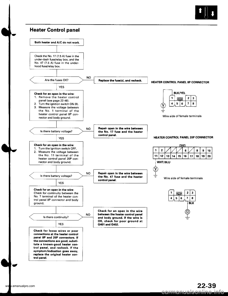
Both heater and A/C do not work.
Check the No. 17 (7.5 A)fuse in theunder-dash fuse/relay box, and theNo. 47 (7.5 A) fuse in the under-hood luse/relay box.
nophcc ih. fur.l.l, .nd r.check.
Check tor rn open in the wiro:1. Remove the heater controlpanellsee page 22 46).2. Turn the ignition switch ON (ll).3. Measure the voltage betweenthe No. 1 terminal of theheater control panel 8P con-nector and body ground.
R.pair opan in lha wlra batw.cnthe No. 1? fuaa and tha h.ltcrcontrol panal.ls thero battery voltage?
Chgck for an opan in th€ wirg:1. Turn the ignition switch OFF.2. Measure the voltage betweenthe No. l l terminal of thoheater control panel 20P con-noctor and body ground.
Repsil opon in tha wi.a batwcanth. No. 47 tur. and tho hoitorcontlol panol.
ls there battery voltags?
Check for an opon in the wire:Ch6ck lor continuity betwoen theNo. 7 terminal of the heater con-trol panel 8P connector and bodyground.
Check for an opon in tho wirab6{woon tho hoatar control p.noland body ground. It the wir. i3OK, chsck for poor ground rtGlOl lnd Glo2.
Check for loose wire3 or oooaconnection3 at the haater controlprnol 8P and 20P connoctors. Itthc conncction3 are good, substi-tuta a known-good h€ater con-trol prnol, and rechecft. lf thesymptom/indic.lion go.3 ewry,repl.cg the original ha.ter con-tlol oancl.
HEATER CONTROL PANEL 8P CONNECTOR
Wire side ot female terminals
HEATER CONTROL PANEL 2OP CONNECTOR
I2A,/1,/58910
1t12131a151517181920
WHT/BLU
Wire side of female terminals
23
{578
BLK
0
www.emanualpro.com
Page 1148 of 1395
A/C System Service
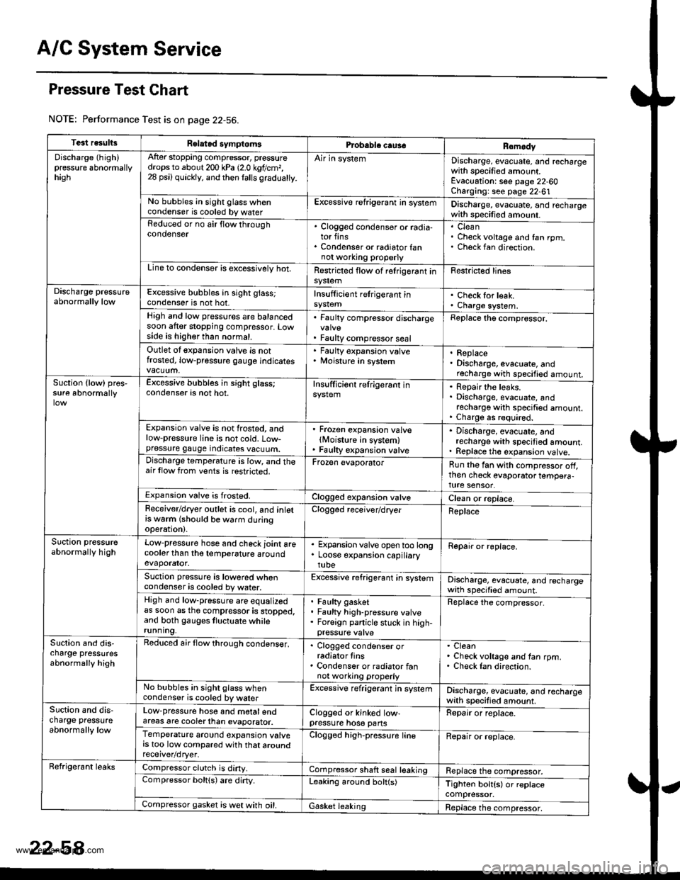
Pressure Test Chart
NOTE: Performance Test is on page 22-56.
Test resultsRelatad symptomsPrcbable caus€Remody
Discharge (high)pressure 6bnormallyhagh
After stopping compressor, pressuredrops to about 200 kPa 12.0 kgtlcm,,28 psi) quickly, and then lalls gradualty.
Air in systemDischarge, evacuate, and rechargewith specified amount.Evacuation: see page 22-60Charging: see page 22-61No bubbles in sight glass whencondenser is cooled by waterExcessive refrigerant in systemDischarge, evacuate, and rechargewith specilied amount.Reduced or no air flow throughcondenser. Clogged condenser or radia-tor fins. Condenser or radiator fannot wo.king properly
CleanCheck voltage and fan rpm.Check fan direction.
Line to condensor is excossivelv hot.Restricted flow of relrigerant insy$emFestricted lines
Discharge pressureabnormally lowExcessive bubbles in sight glass;condenser is not hot.Insufficient retrigerant inCheck for leak.Charge system.High and low pressures are balancedsoon after stopping compressor. Lowside is higher than normal.
. Faulty compressor discharge
. Faulty compressor seal
Replace the comprossor.
Outlet ot expansion valve is notfrosted, low-pressure gauge indicates
' Faulty expansion valve. Moisture in system. Replace. Discharge, evacuate, andrecharge with specified amount.Suction {low) pros,sure abnormallyExcessive bubbles in sight glass;condenser is not hot.Insufficiont relrigerant inRepair the leaks.Discharge, evacuate, andrecharge with specified amount.Charge as r€quired.Expansion valve is not frosted, andlow-pressure line is not cold. Low-pressure gauge indicates vacuum.
' Frozen expansion valvelMoisture in system). Faulty expansion valve
. Discharge, evacuate, andrecharge with specitied amount.. Replace th€ expansion valve.Discharge temperature is low, and theair llow trom vents is restricted.Frozen evaporatorRun the fan with compressor off,then check evaporator tempera,ture sensor.Expansion valve is frosted.Clogged expansion valveClean or replace.Feceiver/dryer outlet is cool, and inlotrs w6rm (should be warm duringoperation).
Clogged receiver/dryerReplace
Suction pressureabnormally highLow-pressure hose and check joint arecooler than tho temperature aroundevaporator.
. Expansion valve open too long. Loose expansion capillarytube
Repair or roplace.
Suction pressure is lowored whencondenser is cooled by water.Excessive refrigerant in systemDischarge, evacuate, and rechargewath specified amount.High and low-pressure are equalizedas soon as tho compressor is stopped,and both gauges tluctuate whilerunning.
Faulty gasketFaulty high-pressure valveForeign panicle stuck in high-
Replace the compressor.
Slction and dis,charge pressutesabnormally high
Reduced air flow through condens€r,. Clogged condenser orradiator tins. Condenser or radiator fannot working properly
CleanCheck voltage and fan rpm.Check Ian direction.
No bubbles in sight glass whencondenser is cooled by walerExcessive refrigerant jn systemDischarge, evacuate, and rechargewith specified amount.Suction and dis-charge pressureabnormally low
Low-pressure hose and motalendareas are cooterlhan evaporator.Clogged or kinked low-pressure hose pansRepair or replace.
Temperature around expansion valvers too low compared with that aroundClogged high-pressure lineRepair or replace.
Refrigerant leaksCompressor clutch is diny.Compressor shaft seal leakingReplace the compressor.Compressor boltls) are dirty.Leaking around bolt(s)Tighton bolt{s) or replacecompressor.Compressor gasket is wet with oil.Gasket leakingReplace the compressor,
www.emanualpro.com
Page 1210 of 1395
Battery
Test
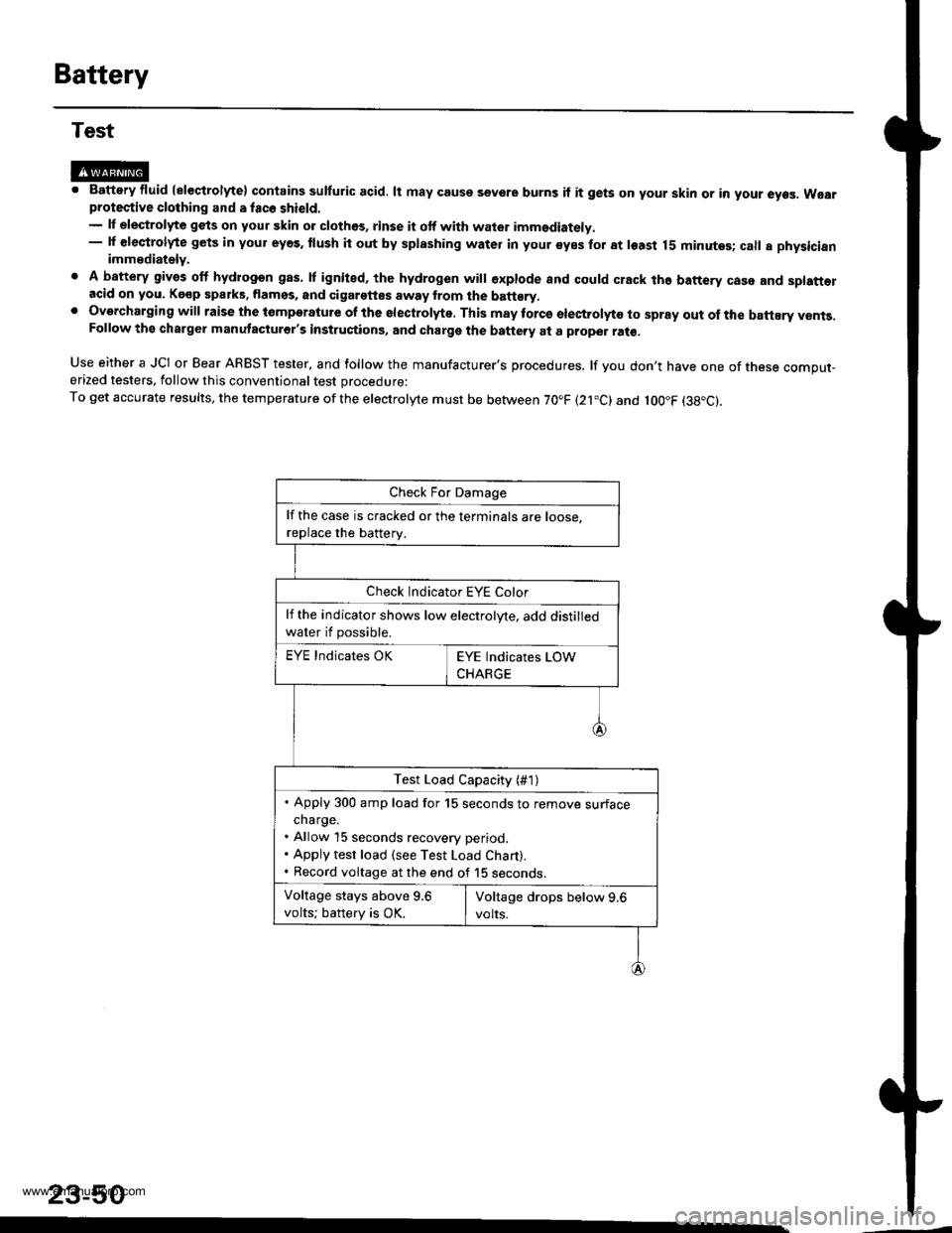
@M. Battery fluid (eleqtrolyte) contains sulturic acid. lt may couse sevore burns if it gets on your skin or in your eyes. Wearprotective clothing and a fac6 shield.- lf elestrolyte gets on your skin o. clothos, rinse it otf with wator imm€diately.- lf €leqtrolyte gets in your eyes. tlush it out by splashing water in your syes for at least 15 minutes; call a physicianimmediately.
. A battery gives off hydrogon gas. lf ignited, the hydrogen will €xplode and could crack the battery case and splatt€racid on you. Kgop sparks. flamss, and cigarettes away from the batt€ry,. Overcharging will raise the tomperatute of the electrolyte. This may torcs electrolyto to spray out of the battEry vents,Follow the charger manutacturer's instructions, and charge the battery at a proper ral€,
Use either a JCI or Bear ARBST tester, and follow the manufacturer's procedures. lf you don't have one of tnese comput-erized testers, follow this conventional test procedure:
To get accurate results, the temperature ofthe electrolyte must be between 70.F (21.c) and loo"F (38"c).
23-50
lf the case is cracked or the terminals are roose.
replace the batterv.
Check Indicator EYE Color
lf the indicator shows low electrolyte, add distilled
water if possible.
EYE Indicates OK
Test Load Capacity (#1)
. Apply 300 amp load for 15 seconds to remove surfacecharge.. Allow 15 seconds recovery period.. Apply test load (see Test Load Chart).. Record voltage at the end of 15 seconos.
Voltage stays above 9.6
volts; battery is OK.
www.emanualpro.com
Page 1211 of 1395
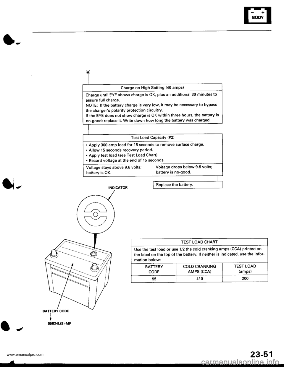
(},
J-
BATTERY CODE
i
5582{LtS)-MF
J
Charge on High Setting (40 amps)
Charge until EYE shows charge is OK, plus an additional 30 minutes to
assure Jull charge.
NOTE: lf the battery charge is very low, it may be necessary to bypass
the charger's polarity protection circuitry.
lf the EYE does not show charge is OK within three hours, the battery is
no-good; replace it. Write down how long the battery was charged.
Test Load Capacity (#2)
. Apply 300 amp load for 15 seconds to remove surface charge.
. Allow 15 Seconds recovery period,
. Apply test load (see Test Load Chart).
. Record voltage at the end ot 15 seconds.
Voltage drops below 9.6 volts;
battery is no-good,Voltage stays above 9.6 volts;
battery is OK.
TEST LOAD CHART
Use the test load or use 1/2 the cold cranking amps (CCA) printed on
the label on the top of the battery. lf neither is indicated. use the infor-
mation below:
BATTERY
CODE
COLD CRANKING
AMPS (CCA)
TEST LOAD
{amps)
55410200
J
23-51
www.emanualpro.com
Page 1222 of 1395
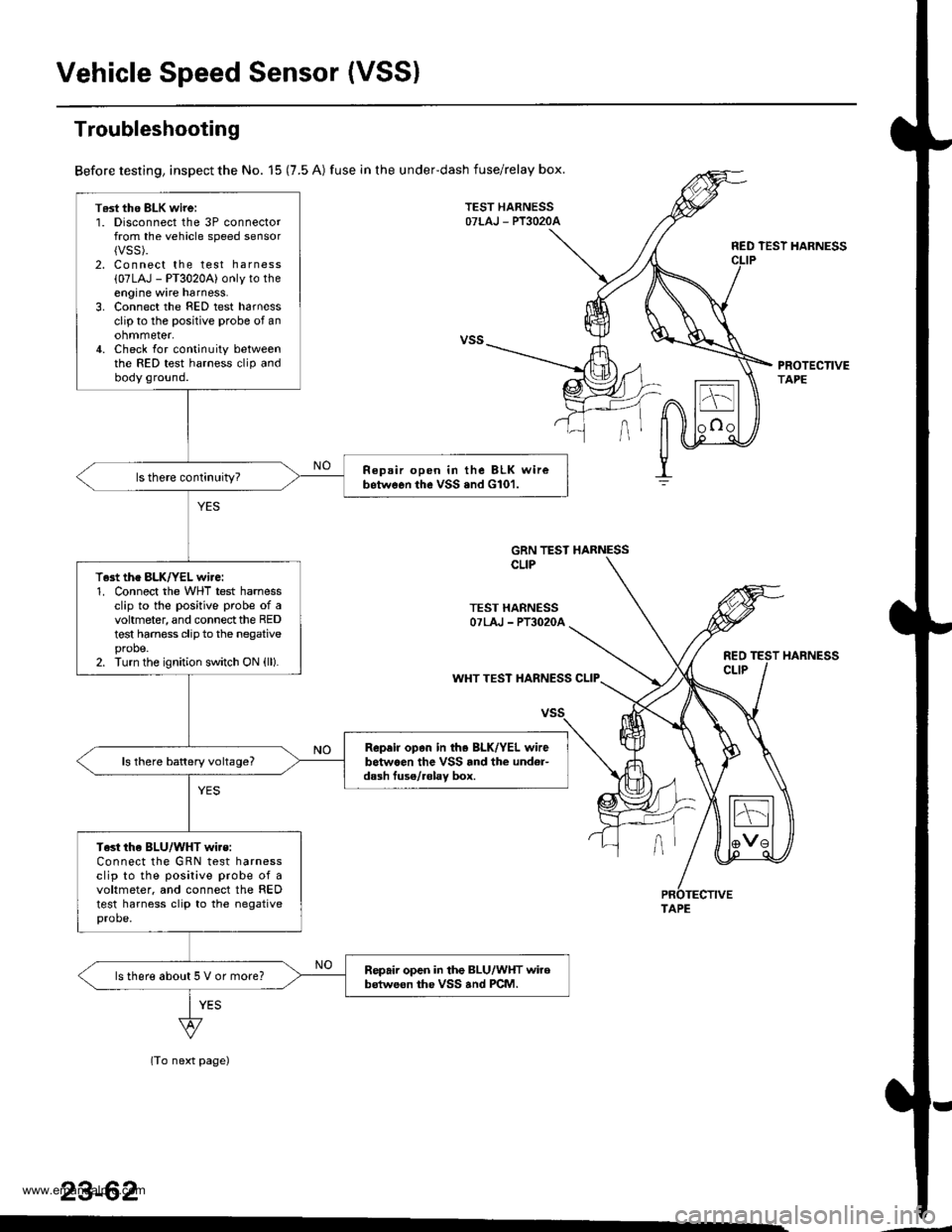
Vehicle Speed Sensor (VSSI
T6st tho BLK wirei1. Disconnect the 3P connectorfrom the vehicle speed sensor{VSS).2. Connect the test harness
{07LAJ - PT3020A) only to theengine wire harness.3. Connect the FED test harnessclip to the positive probe of anohmmeter,4. Check for continuity betweenthe RED test harness clip andbody ground.
Repair open in the BLK wirebetwGon the vSS .nd G101.
T.st the BLK/YEL wire:1. Connect the WHT test harnessclip to the positive probe of avohmeter, and connect the REDtest harness clip to the negativeprobe.2. Turn the ignition switch ON (ll).
Rep.ir op.n in th. BLK/YEL wirebetwaen the VSS rnd the und6r-dash fuse/.6lav box.ls there battery voltage?
Test the BLU/WHT wi.s:Connect the GRN test harnessclip to the posilive probe of avoltmeter. and connect the REDtest harness clip to the negativeprobe.
Repair open in the BLU/WHT wirobstweon the VSS and PCM.ls there about 5 V or more?
Troubleshooting
Before testing, inspect the No. 15 (7.5 A) fuse in the underdash fuse/relay box.
TEST HARNESSOTLAJ - PT3O2OA
RED TEST HARNESS
PROTECTIVETAPE
GRN TEST HARNESSCLIP
TEST HARNESSOTLAJ - PT3O2OA
REOCLIPWHT TEST HARNESS CLIP
(To next page)
23-62
HARNESS
TAPE
www.emanualpro.com
Page 1223 of 1395
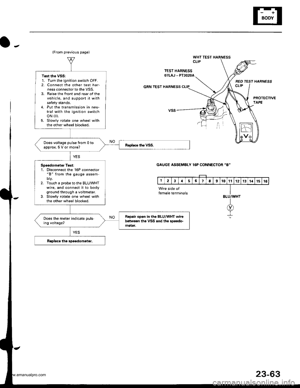
o-.
WHT TEST HARNESSCLIP
TEST HARNESSOTLAJ _ PT3O2OA
GRN TEST HARNESS
BED TEST HARNESSct-tP
PROTECTIVETAPE
(From previous page)
T6st the VSS:1. Turn the ignition switch OFF.2, Connect the other test har-ness connector to the VSS,3. Raise the front and rear of thevehicle, and support jt withsafety stands.4. Put the transmission in neu-tral with the ignition switchoN r).5. Slowly rotate one wheel withthe other wheel blocked.
Does voltage pulse from 0 toapprox, 5 V or more?
Spoodom6tor T6st:1, Disconnect the 16P connector"B" from the gauge assem
2. Touch a probe to the BLUMHTwire. and connect it to bodyground through a voltmeter.3. Slowly rotate one wheel withthe other wheel blocked.
R.p.ir opon in the BLU/WHT wirebetwe€n the VSS and the 3oeedo-mgter.
Does the meter indicate puls-ing voltage?
GAUGE ASSEMBLY 16P CONNECTOR 'B-
Wire side offemale termin6lsBLU/WHT
I(v)
It
23-63
www.emanualpro.com
Page 1229 of 1395
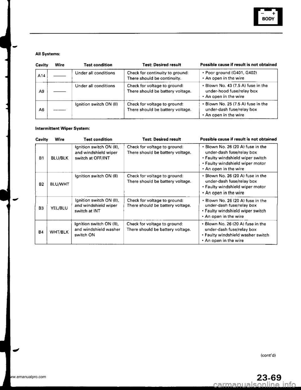
All Systems:
Cavity WireTest condition
Tost condition
Test: Desired r€sult
Test: Desired result
Intermittent Wipol System:
Cavity Wire
Possible cause if result is not obtained
Possible causs if result is not obtained
414Under all conditionsCheck for continuity to ground:
There should be continuity.
. Poor ground (G401, G402). An open in the wire
A9
Under all conditionsCheck for voltage to ground:
There should be battery voltage.
. Blown No. 43 (7.5 A) fuse in the
under-hood fuse/relay box. An open in the wire
A6
lgnition switch ON (ll)Check for voltage to ground:
There should be battery voltage.
. Blown No. 25 (7.5 A)fuse in the
underdash fuse/relay box. An open in the wire
B1BLU/BLK
lgnition switch ON (ll),
and windshield wiper
switch at OFF/lNT
Check for voltage to ground:
There should be battery voltage.
Elown No. 26 (20 A)fuse in the
under-dash fuse/relay box
Faulty windshield wiper switch
Faulty windshield wiper motor
An open in the wire
82BLUrur'HT
lgnition switch ON (ll)Check for voltage to ground:
There should be battery voltage.
Blown No.26 (20 A) fuse in the
under-dash fuse/relay box
Faulty windshield wiper motor
An open in the wire
B3YEVBLU
lgnition switch ON (ll),
and windshield wipe.
switch at INT
Check for voltage to ground:
There should be battery voltage.Blown No. 26 (20 A) tuse in theunder-dash fuselrefay box
Faulty windshield wiper switch
An open in the wire
B4WHT/BLK
lgnition switch ON (ll),
and windshield washer
switch ON
Check for voltage to ground:
There should be battery voltage.
Blown No. 26 (20 A) fuse in the
under-dash fuse/relay box
Faulty windshield washer switch
An open in the wire
(cont'd)
23-69
www.emanualpro.com