Page 608 of 1395
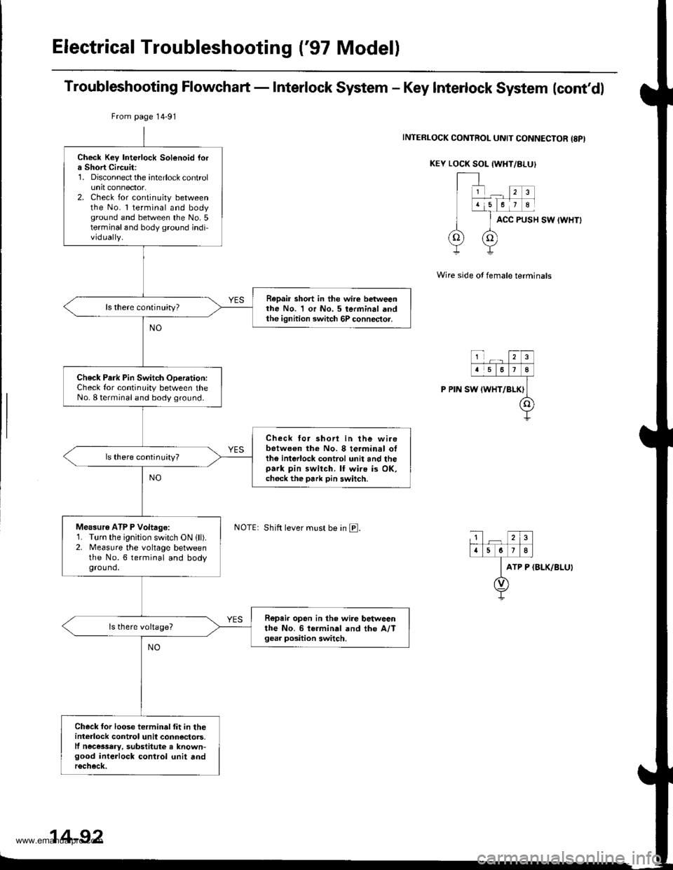
Electrical Troubleshooting {'97 Model)
Troubleshooting Flowchart - Interlock System - Key Interlock System lcont'dl
INTERLOCK CONTROL UNIT CONNECIOR {8PI
KEY LOCK SOL {WHT/8I-UI
ACC PUSH SW IWHTI
Wire side of female terminals
ATP P (BLK/BLU)
Check Key Interlock Solenoid fora Short Circuit:1. Disconnect the interlock controlunit connector.2. Check for continuity betweenthe No. l terminal and bodyground and between the No.5terminaland body ground indi-vidually.
Repair short in the wire betweenthe No. 1 or No. 5 terminal andthe ignition switch 6P connector.
ls there continuity?
Check Park Pin Switch ODeration:Check for continuity between theNo. I terminal and body ground.
Check tor shori in the wirebetwo€n the No. 8 terminal otthe interlock control unit and thepark pin switch. lf wire is OK,ch6ck the park pin switch.
ls there continuity?
Measu16 ATP P Voltage:1. Turn the ignition switch ON lll).2. Measure the vohage betweenthe No.6 terminal and bodyground.
R6pei. open in the wire betweenthe No. 6 i€rminal and the A/Tgea. position switch.
Check for loose terminalfit in theinterlock control unil connectors.lf necessery, substitute a known-good interlock control unit andr6check.
From page 14-91
Shift lever must be in E.
14-92
www.emanualpro.com
Page 609 of 1395
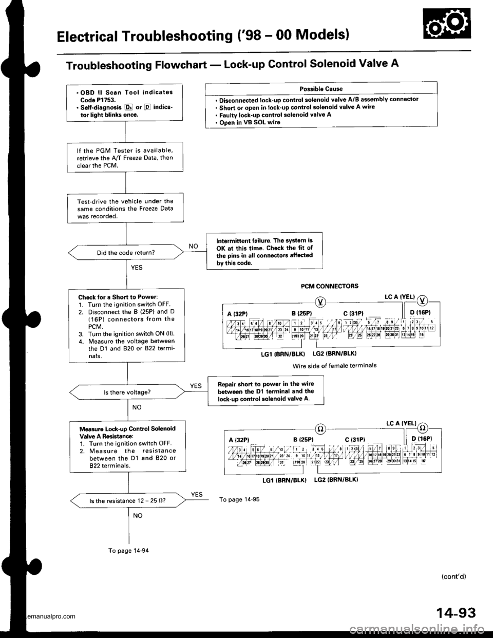
Electrical Troubleshooting ('98 - 00 Models)
Troubleshooting Flowchart - Lock-up Control Solenoid Valve A
Poslible Cause
. Dbconnected lock-up control solenoid valve A/B assemblY connector. Short or open in lock-up control solenoid valve A wire. Faulty lock-up control solenoid valve A' Open in vB SOL wire
LGI|BRN/BLK) LG2IBRN/BLK)
To page 14 95
(cont'd)
14-93
A t32Pli r rriltI l,1 I I ltDrste,0n,,2. t3r B'r!51 r.
LGl IBRN/BLKI LG2 (BRN/BLKI
Wire side of female terminals
A {32P)
.OBD ll Scan Tool indicatesCode Pl753.. Self-di.gnosis E or E indica-
tor light blinks once.
lf the PGM Tester is available,retrieve the M Freeze Data, then
clear the PCM.
Test-drive the vehicle under the
same conditions the Freeze Data
lntermittent failul.. The system is
OK at this time. Check the fit of
the Din3 in all connectors affected
by thb code.
Did the code return?
Check for a Short to Power:'1. Turn the ignition switch OFF.
2. Disconnect the B (25P) and D(16P) connectors trom thePCM,3. Turn the ignition switch ON (ll).
4. Measlre the voltage betweenthe D1 and 820 or 822 termi-nals,
n€pair short lo power in the wire
betw€€n the Dl terminal and the
lock-up control solenoid valve A
Mg.sure Lock-up Control SolenoidValve A Rssistance:1. Turn the ignition switch OFF.2. M easu re the resistancebetween the D1 and 820 or822 terminals.
ls the resistance 12 - 25 o?
To page 14-94
www.emanualpro.com
Page 610 of 1395
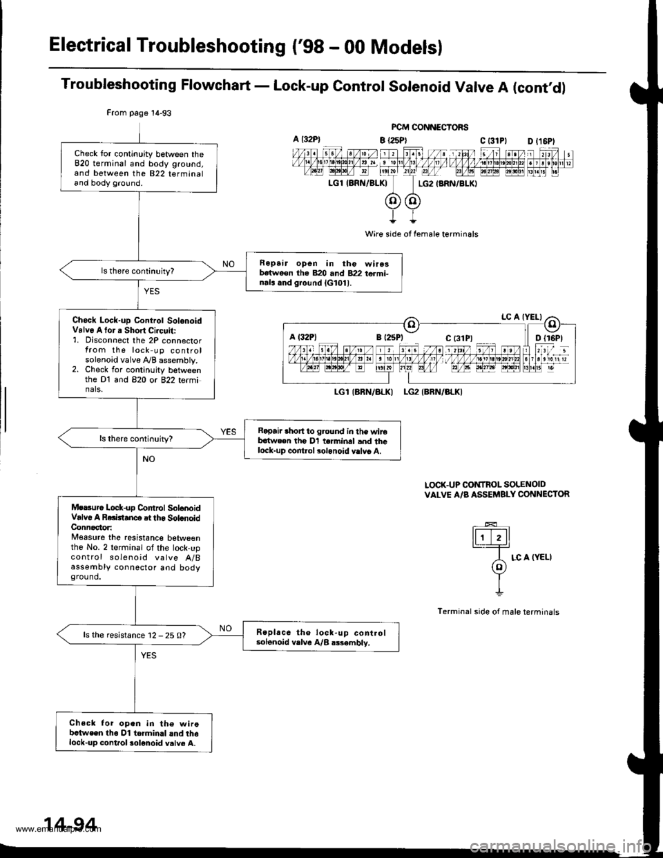
Electrical Troubleshooting ('98 - 00 Models)
Troubleshooting Flowchart - Lock-up Control Solenoid Valve A (cont'dl
FCM CONNECTORS
B {25P} C t31Pl
Wire side ot female terminals
LGlIARN/ALKI LG2IBRN/BLKI
LOCK-UP CONTROL SOLENOIDVALVE A/B ASSEMBLY CONNECTOR
tFttl._T=
A LC A (YELI(o)Y
I
Terminal side of male terminals
From page 14-93
Check tor continuity between theB20 terminal and body ground,and between the 822 terminaland body ground.
Ropair open in the wire3b€tweon tha 820 and 822 termi-nals and ground lG101l.
Ch6ck Lock-up Control SolonoidValv6 A tor a Short Ci.cuit:'1. Disconnect the 2P connectorfrom the lock up controlsolenoid valve A/B assembly.2. Check for continuity betweenthe Dt and B2O or 822 te(minals.
Ropai. lhort to g.ound in the wireb€twe€n the Dl terminal and thelock-up control solonoid vslvg A.
Mersurg Lock-up Co|ttrol SolonoidValvo A Rolktanco at tho SolonoidConnoctor:Measure the resistanco betweenthe No. 2 terminal of the lock,upcontrol soleno;d valve A/Bassembly connector aod bodyground.
Replace the lock-up controlsolonoid vrlve A/B a$ambly,ls the resistance 12 - 25 0?
Chsck for open in th€ wircbctwe€n tho Dl terminal lnd th6lock-up cont.ol solonoid v.lve A.
a t32P)D l16Pl
a l32Plc t3lPl
14-94
www.emanualpro.com
Page 612 of 1395
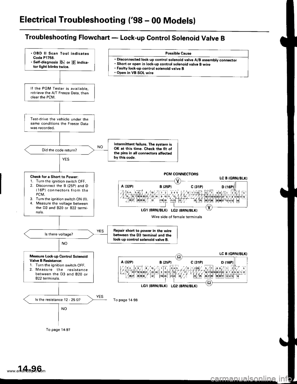
Electrical Troubleshooting ('98 - 00 Models)
Troubleshooting Flowchart - Lock-up Control Sotenoid Valve B
Possibl€ Cause
. Disconnected lock-up control solenoid valve A/8 assembly connector. Short or open in lock-up control solenoid valve B wire. Fauhy lock-up control solenoid valve B. Open in VB SOL wir€
PCM CONNECTORSLC B {GRN/8LKI
LG1{BRN/BLK} I-G2{BRN/BLK)
Wire side of female terminals
A {32P1
To page 14 98
.OBD ll Scan Tool indicatesCode P'l758.. Sell-diagnosis Dl or E indica-tor light blinks twic€.
lf the PGM Tester is available,relrieve the A,/T Freeze Data, thenclear the PCM-
Test-drive the vehicle under thesame conditions the Freeze Data
Interm ittant tailure. The lystem isOK at this time. Check the tii ottho pin3 in all connectors athedby this code.
Did the code return?
Check for a Short to Pow€r:1. Turn the ignition switch OFF.2. Disconnect the B 125P) and D(16P) con nectors lrom thePCM.3. Turn the ignition switch ON 1ll).4. Measure the voltage betlveenthe D3 and 820 or 822 termi-nals.
Repair shon to power in the wirebetween tho D3 terminal and thelook-up control solenoid valve B.
Measure Lock-up Control SolanoidValve B Resistanc€:1. Turn the ignition switch OFF.2. Measure the resistancebetween the D3 and 820 or822 terminals.
ls the resistance 12 - 25 O?
To page 14-97
www.emanualpro.com
Page 613 of 1395
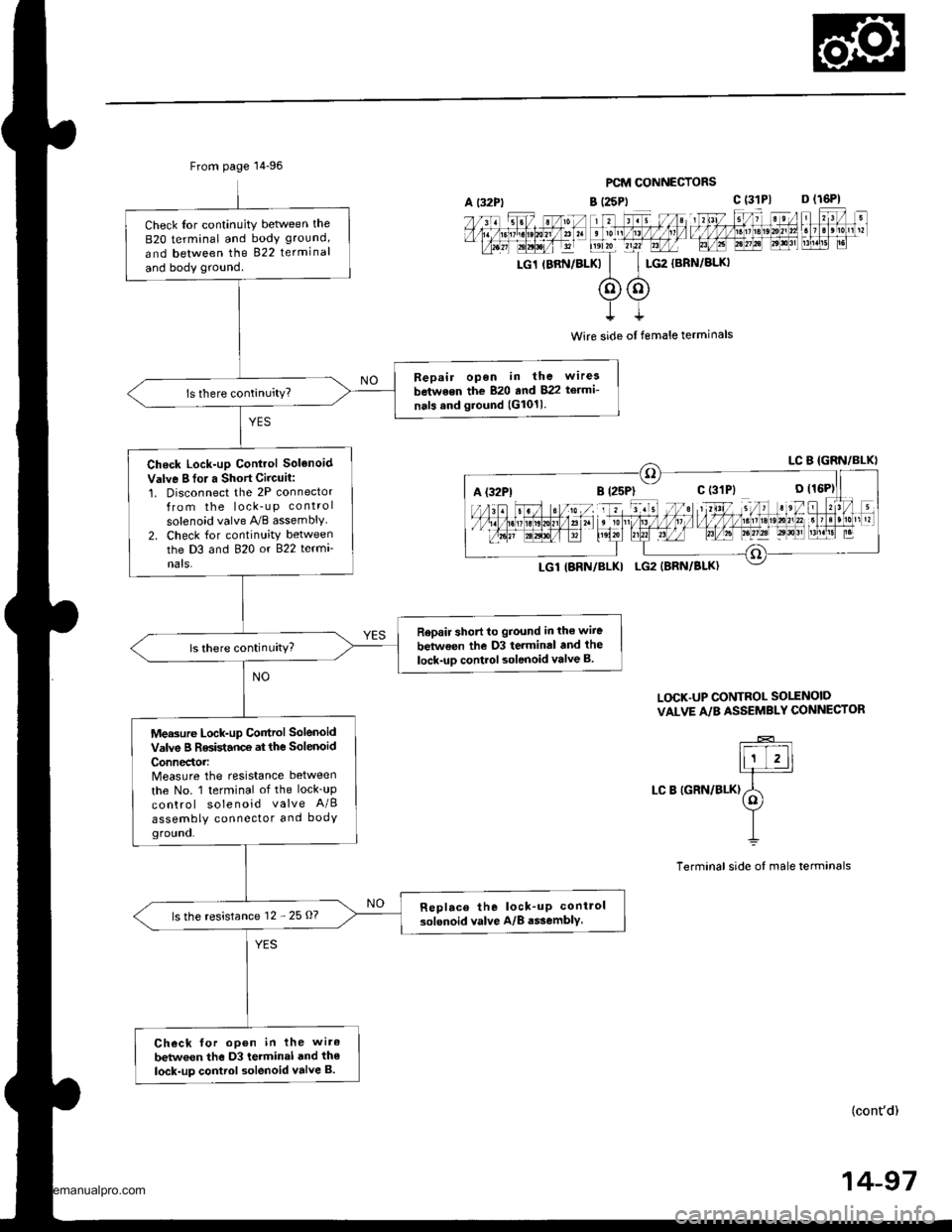
From page 14-96
Check Ior continuity betlveen the
B2O terminal and body ground,
and between the 822 terminal
and body ground.
Bepair open in the wirea
between the 820 and 822 te.mi-
nals and ground (G1011.
Check Lock-up Control Solenoid
Valve I fo. a Short Circuit:1. Disconnect the 2P connectorfrom the lock_u p control
solenoid valve A,/B assembly2. Check for continuity betweenthe D3 and 820 or 822 termi
nats.
Rep.ir short to ground in the wiie
between the D3 terminal and the
lock-uD control solenoid valve B.ls there continuity?
Measure Lock-up Control Solenoid
valve B Resistance at the solenoid
ConnedoMeasure the resistance between
the No. 1 terminal of the lock_up
control solenoid valve A/B
assembly connector and bodYground.
Replace the lock_up conirol
solenoid valve A/8 a$embly.ls the resistance 12 - 25 O?
Check for open in the wiro
betwoen the D3 terminal and the
lock-up control solenoid valve B.
PCM CONNECTORS
B (25Pt c (31P1 D (16P1
rc1 rBRN/BLKk'
c$G2
{BRN/BLKI
t
Wire side ol female terminals
L(rcK.UP CONTROL SO1TNOID
VALVE A/B ASSEMBLY CONNECTOR
LC B IGRN/BLK)
(cont'd)
14-97
A {32P1
www.emanualpro.com
Page 614 of 1395
Electrical Troubleshooting ('98 - 00 Modelsl
Troubleshooting Flowchart - Lock-up Control Solenoid Valve B (cont,d)
From page 14 96
PCM CONNECTORSVB SOL (BLK/YEL}
LG1 (BBN/8LKI LG2 (BRN/BLKI
Wire side of Iomale terminals
Measuro VB SOL Voltago:1. Turn the ignition switch ON llt).2. Measure the voltage betlveenthe D5 and 820 or 822 terminals,
Check tor blown No. t5 (7.5 Alfuse in the underdash fu36/.elaybox. lf th6 fuse is OK, ..pair openin the wire betwooo tho D5 t.rmi-nel and thg underdash two/relayItox.
ls there battery voltage?
Check for loose terminal lit in thePCM connectors. ll n€ces3a.y,substitute a known-good pCM
and .€check.
A l32P)
14-98
www.emanualpro.com
Page 619 of 1395
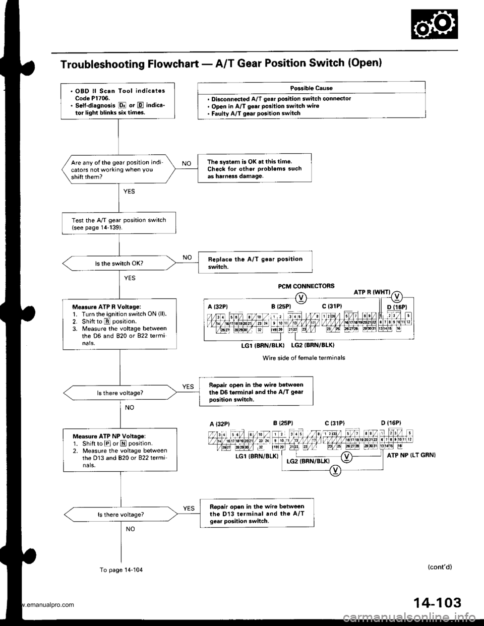
Troubleshooting Flowchart - A/T Gear Position Switch (Open)
Po$iblg Cause
. Dbconnected A/T gear position switch connoctor. Open in A/T gear po3ition switch wiro. Faulty A/T g€ar position switch
Wire side of female terminals
LGl {SRN/BLK)
{cont'd)
P,CM CONNECTORS
LGT(BNN/BLKI LG2IBRN/BLK)
A {32P)c l31P)
ATP NP (LT GRN}
. OBD ll Scan Tool indicatesCodo Pl706.. Self-diagnosis Fl or E indica-to. lighl blinks six times.
The system is OK.tthis time.Check for oth6r probl€ms suchas harne3s damage.
Are any ofthe gear position indicators not working when you
shift them?
Test the A/T gear position switch(see page 14-139).
Measure ATP R Vohago:1. Turn the ignition switch ON (ll).
2. Shitt to E position.
3. Measure ihe voltage betweenthe D6 and 820 ot 822 tetfiinals,
Repair open in tho wiro betwoenthe D6 terminal and the A/T gear
oosition switch.
Measure ATP NP Volt.g€:1. Shift to Elor E position.
2. Measure the voltage betweenthe D13 and 820 or 822 terminals,
Repair open in the wiro betweenth€ Dl3 terminal and th€ A/Tgesr posilion awitch.
To page 14-104
14-103
www.emanualpro.com
Page 620 of 1395
Electrical Troubleshooting ('98 - 00 Model)
Troubleshooting Flowchart - A/T Gear Position Switch (Open) (cont'd)
PCM CONNECTORS
B {25Ptc (31P|
LGl IERN/BLKI
Wire side of female terminals
LGl {BRN/BLKI
LGl {BRN/ELXI
From page 14-103
Me.sure ATP D4 Vohrge:1. Shift to E 1'98) or E ('99 -
00) position.2. Measure the voltage betweenthe Dg and 820 or 822 termi-nats.
Repair opon in th6 wire betweentho m tarminal and the A/T gealposition swhch.
Me..ure ATP 03 Vohage l'98modell:1. Shift to E position.2. Measure the voltage betweenthe DB and 820 or 822 tetmi-nals,
Repair open in the wire botwoonth6 08 terminal .nd the A/T geatposition switch (381.
Measuro ATP 2 Voltage:1. Shilt to E position.2. Measure the voltage betweenthe D14 and 820 or 822 terminats.
Repair opon in the wire betweenthe D14 t€.minal end the A,/Tgear po3ition switch,
To page 14 105
www.emanualpro.com