Page 583 of 1395
Check Lock-up Control SolenoidValve B lor a Short Circuit:1. Disconnect the 2P connectorfrom the lock-up control solenoid valve A/8 assembly.2. Check for continuity betweenthe 84 and A9 or A22 lermi_nals-
Repair short to ground in the wirebetween the 84 lerminal and the
lock-up conlrol solenoid valve B.
Me6aure Lock-up Control Sole_noid Valve B Resistance at the
Solenoid Valve Connector:Measure the resistance betweenthe No. 1 terminal of the connec-
tor and body ground.
Check lor open in the wire
bctween the 84 terminal and thelock-up control solenoid volva B.ls the resistance 12 - 25 0?
Replace the lock-up conttol sole-noid valve A/B ass6mbly.
From page 14 66PCM CONNECTORS
Wire side of female terminals
LOCK-UP CONTROL SOLENOID
VAI-VE A/B ASSEMBLY CONNECTOR
LC B (GRN/BLK)
14-67
www.emanualpro.com
Page 587 of 1395
From page 14-70
Measure ATP D3 Vohag€:1. Shift to E position.
2. Nleasure the voltage betweenthe 88 and Ag or A22 terminals,
Repair open in the wirg bstween
the 88 tolminal and tho A/l gear
oo3ition 3witch.
Msasure ATP2 Volttg6:'1. Shiftto E position.
2. Measure the voltage between
the 817 and A9 or A22 termi'nals.
Repair open in lhe wire between
the 817 terminal and tho A/Tgear position switch.
Moasure ATP1 Voltage:1. Shift to A position.
2. Measure the voltage betweenthe 818 and Ag or A22 termi-nats,
R€pair opon in the wiro betweenthe 818 terminll and the A/Tgoar poshion switch.
Check tor looso terminal fit in thePCM connectors. lf necossarY,substitute a known-good PCM
and rechock.
FCM CONNECTORS
Wire side of female terminals
www.emanualpro.com
Page 588 of 1395

Electrical Troubleshooting ('97 Model)
Troubleshooting Flowchart - Shift Control Solenoid Valve A
. Disconnected shift control solenoidvalve A/8 a$embly connector. Short or open in shift control sole-noid valve A wire
Possible Causo
shift control solenoid valve A
lf the Honda PGMTester is available:
I
PCM CONNECTORS
Wire side of female termin6ls
. OBD ll Scan Tool indicates CodeP0753.. Self-diagnosk E indicator lightblinks seven tim€s.
Check and record the freeze datain case it is needed later for problem verification.
Perform the shift control solenoidvalve A test using the HondaPGM Tester.
The sol€noid is OK at this time.Verify that all connectors in thecircuit are making good contact.
Did the solenoid pass the test?
Check tor a Short to Power:1. Turn the ignition switch OFF.2. Disconnect the A (32P) and B(2 5P) connectors from thePCM.3. Turn the ignition switch ON lll).4. Measure the voltage betweenthe 83 and Ag or A22 terminals.
Repair short to power in the wirebetween the 83 terminal and theshift control solenoid valve A.
Measure Shift Control SolenoidValve A Resistanco:1. Turn the ignition switch OFF.2, Measure the resistancebetween the 83 and A9 or A22termrnals,
Check tor loose terminal tit in thePCM connectors, lf necessaay,subslituie e known-good sole-noid valve assemblv or PCM andrech€ck.
ls the resistance 12 25 {)?
To page l4-73
14-72
www.emanualpro.com
Page 591 of 1395
From page 14-74
Check Shift Control SolenoidValvo B tor a Short Circuil:1. Disconnect the 2P connectorfrom the shift control solenoidvalve y'y'8 assembly.2. Check for continuity betweenthe 811 and Ag or A22 termi-nals,
Ropair short to ground in the wireb64w€€n tho 811 torminal and lhgshift control solenoid valvo B.
Meesure Shift Control SolenoidValve B Rosistance at lh€ Sole-noid Vrlve Connector:Measure the resistance betweenthe No. 2 terminal ol the connector and body ground.
Check tor open in the wirebdtweon the 811 torminal and theshift control sol€noid valv6 B.ls the resistance 12 - 25 O?
Reolace the shift control solenoidvalve A/B asJembly,
PCM CONNECTORS
Wire side of female terminals
SHIFT CONTROL SOLENOIDVALVE A/B ASSEi'BLY CONNECTOR
ti;Tll
I sH B |GRN/W{T|
o
YII
Terminal side of male terminals
14-75
www.emanualpro.com
Page 593 of 1395
Ch€ck CounteGh!ft Spocd Sonsoifor a Short Cirruit:1. Disconnect the B 125P) con'nector lrom the PCM.2. Check for continuity botweenthe body ground and the B23terminal and 822 term ina Iindividually.
Repair short in tho wirgs b€twoentho 823 ,nd 822 te.minals andthc countaBhaft sp€€d senso..
Mersuro Countorrhrtt Spoed Son-sor qrcuit tor an Open:'1. Connect the countershaftspeed sensor 2P connector,2, Measure the resistancebetween the 823 and 822 termrnals.
Rapair loor€ t.rminll or opon intho wircs betwoon tho 823 .nd822 terminrl! .nd th. countaFshaft specd san3or.
ls the resistance 400 - 600 0?
Check for loo3e terminsl fit in thePCM connecto13. It necess!ry,sub3titulg s known-good PCMand rochock.
PCM CONNECTOR B I25PI
Wire side of lemale terminals
14-77
www.emanualpro.com
Page 594 of 1395

Electrical Troubleshooting {'97 Model)
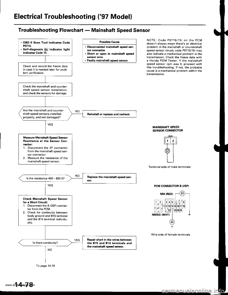
Troubleshooting Flowchart - Mainshaft Speed Sensor
Po$ible Cau3o
. Disconnocted mainshaft speod sen-sot connectot. Short or open in mainsh.ft sp6ed
' Faulty meinshaft spoed sensor
NOTE: Code P0715115) on the PCMdoesn't always mean there's an electricalproblem in the mainshaft or counlersharlspeed sensor circuit; code P0715(15) mayalso indicate a mechanical problem in thetransmission. Check the freeze data witha Honda PGM Tester. lf the mainshaftspeed sensor rpm was 0, proceed withthis troubleshooting. lf not, the probablecause is a mechanical problom within thetransmission,
MAINSHAFT SPEEOSENSOR CONNECTOR
_E_
ItiT,ll-F=r
9t
LJ
Terminal side of male terminals
PCM CONNECTOR B {25P'
Wire side of female terminals
. OBD ll Scan Tool indic.t6 Codem715.. Self-diagnosis E indic.tor lightindicatag Code 15.
Check and record the freeze datain case it is needed later {or prob,lem verification.
Check the mainshaft and counter-shaft speed sensor installation,and checkthe sensors for damage.
Are the mainshaft and counter-shaft speed sensors installedproperly, and not damaged?Reingtall or reolace and recheck.
Meaaure MaiNhatt Spoed Sen3orR6sist!nce at the Sensor Con-necaor:1. Disconnect the 2P connectorfrom the mainshaft speed sen-sor connector.2. lreasure the resistance of themainshaft speed sensor.
ls the resistance 400 - 600 O?
Check Mainahaft Speed Sensortor a Short Circuit:1. Disconnect the B (25P) connec-tor lrom the PCM.2. Check for continuity betlveenbody ground and 815 terminaland the 814 terminal individu-
ReDair short in the wir€6 b€t reenthe 815 and 814 torminals andthe mainsh!ft sp€ed sensor.
To page l4-79
14-78
www.emanualpro.com
Page 595 of 1395

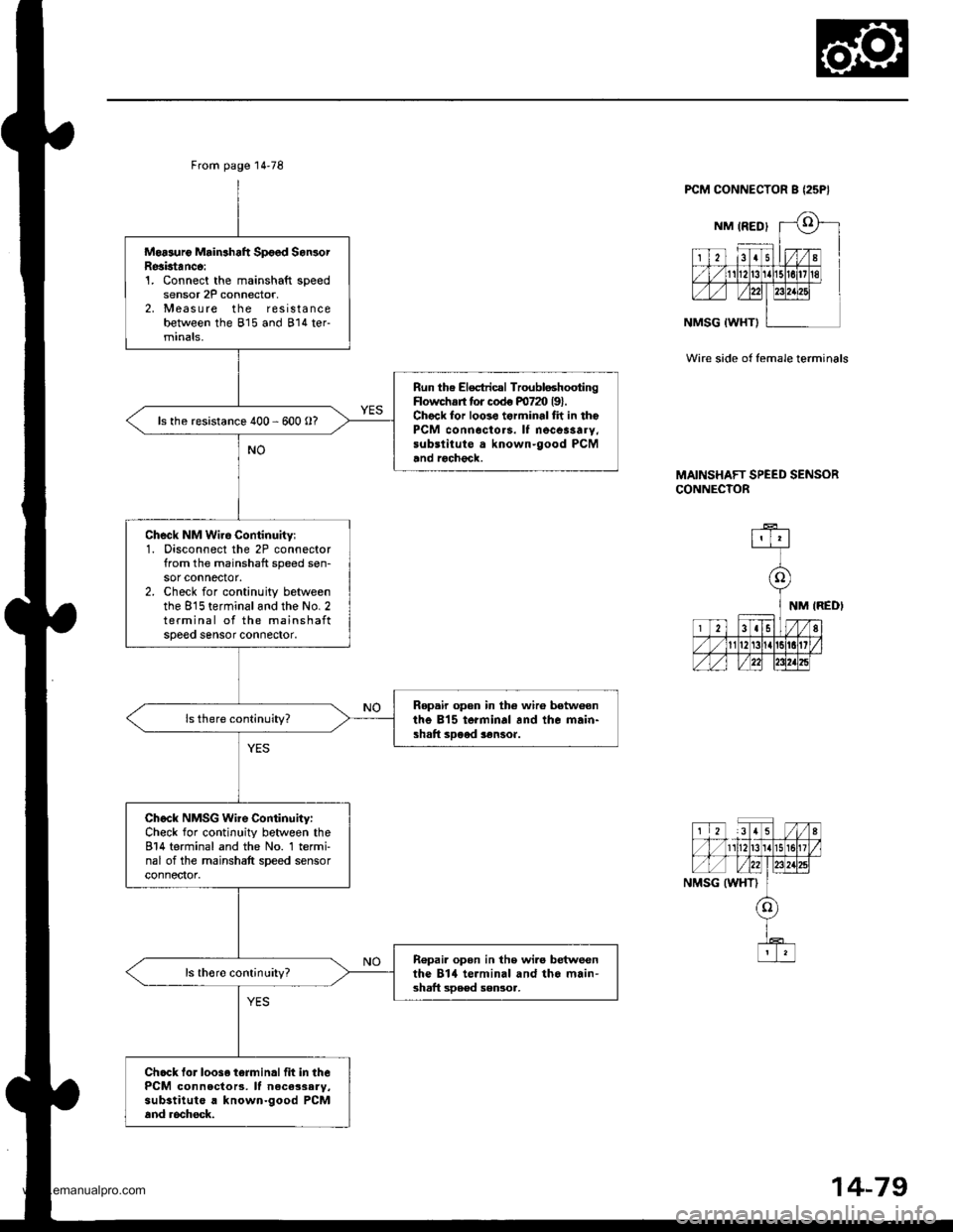
From page 14'78
Moasuro Mrin3haft Spoed SanlorResktanco:1. Connect the mainshaft speedsensor 2P connector,2, Measure the resistancebetween the 815 and 814 ter-minals,
Run the Electricrl TroubloshootingFlowchs tor codo m72O l9l.Chock for loo3e torminal fh in thePCM conn6cto.s. It necessarY,substitute a known-good PCMand rochgck.
ls the resistance 400 - 600 O?
Check NM Wiro Continuity:1. Disconnect the 2P connectorfrom the mainshaft speed sen-sor connector.2. Check for continuity betweenthe 815 terminaland the No.2terminal of the mainshaftspeeo sensor conneoor.
Ropair open in the wir6 betw€onthe 815 terminal and the main-shaft sDood $nsoa.
Check NMSG Wire Continuity:Check for continuity between the814 terminal and the No. 1 termi-nal of the mainshaft speed sensorconnector.
R€pai. opon in the wi.o betweenthe Bltl terminal and tho main'3haft sDe€d sensoa,
Ch.ck lor loos. t6rminallit in thePCM connecto13, lf neca3sary,substitute a known-good PCMand rochock.
PCM CONNECTOR B {25P}
Wir€ side of female terminals
MAINSHAFT SPEED SENSORCONNECTOR
14-79
www.emanualpro.com
Page 596 of 1395

Electrical Troubleshooting ('97 Modell
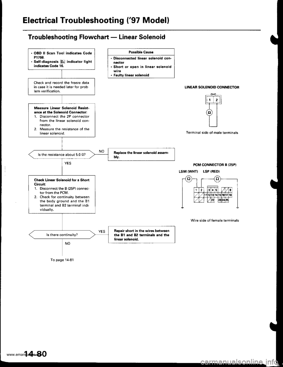
Troubleshooting Flowchart - Linear Solenoid
Possible Caus€
. Disconnocted linear solenoid con-
. Short or oDen in linear solenoid
. Fsultv linear solenoid
SOLENOID CONNECTOR
t-TTI�t]]lt
tl I ? rl-T�r
atll
L_l
PCM CONNECTOR B I25PI
LSM {WHTI LSP {RED)
LINEAR
Terminal side ot male terminals
Wire side of lemale terminals
. OBD ll Scan Tool indicates CodeP1768.. S.lt-diagnosis E indicator lightindicat* Code 16.
Check and record the freeze datain case it is needed later for prob
lem verification.
M€ssurc Linear Solanoid Re3ist-ance ei th€ Solonoid Connoctor:1. Disconnect the 2P connectorfrom the linear solenoid con-nector,2, Measure the resistance ol thelinear solenoid.
ls the resistance about 5.0 O?
Check Linear Solenoid {or a ShortCileuit:1. Disconnect the B (25P) connector from the PCM.2. Check for continuity betweenthe body ground and the B1terminal and 82 terminal individually.
Rooair short in the wires betweenthe Bl end 82 terminek .nd thelinear solenoid.
To page 14-81
www.emanualpro.com