Page 982 of 1395
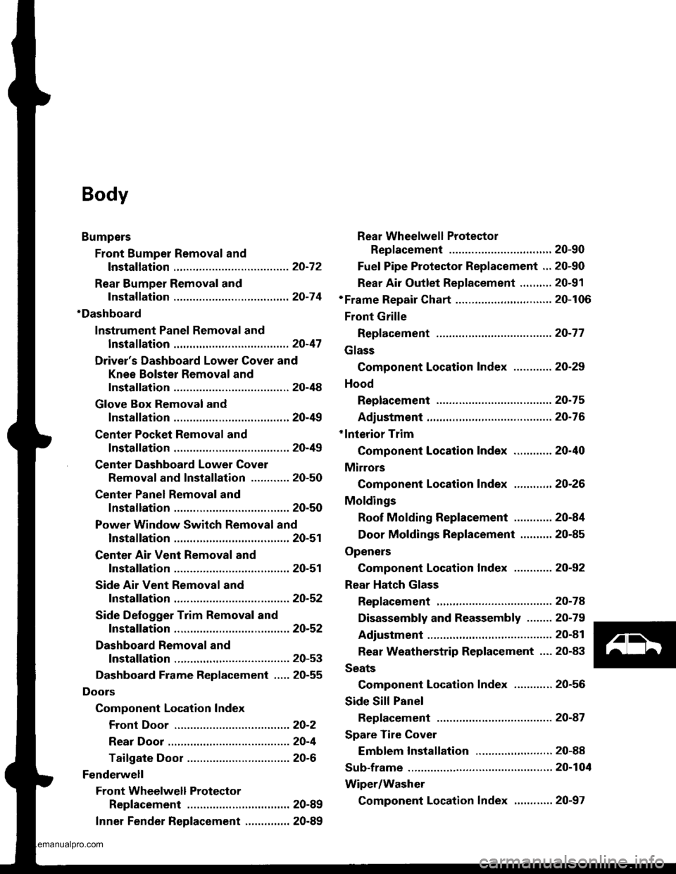
Body
Bumpers
Front Bumper Removal and
fnstaflation .........20-72
Rear Bumper Removal and
fnstaflation .........20-74
'Dashboard
lnstrument Panel Removal and
lnstallation .........20-47
Driver's Dashboard Lower Cover and
Knee Bolster Removal and
Installation .........20-48
Glove Box Removal and
lnstallation .........20-49
Center Pocket Removal and
lnstallation .........20-49
Center Dashboard Lower Cover
Removal and lnstallation ............ 20-50
Center Panel Removal and
lnstallation .........20-50
Power Window Switch Removal and
lnstallation .........20-51
Center Air Vent Removal and
lnstallation .........20-51
Side Air Vent Removal and
fnstallation .........20-52
Side Defogger Trim Removal and
fnstallation .........20-52
Dashboard Removal and
lnstallation .........20-53
Dashboard Frame Replacement ..... 20-55
Doors
Component Location Index
Front Door ,,...,,,,20-2
Rear Door ...........20-4
Tailgate Door ................................ 20-6
Fenderwell
Front Wheelwell Protector
Replacement .....20-89
Inner Fender Replacement .,.....,.,.... 20-89
Rear Wheelwell Protectol
Replacement .....20-90
Fuel Pipe Protector Replacement ... 20-90
Rear Air Outlet Replacement .......... 20-91
*Frame Repair Chart .............................. 20-106
Front Grille
Repf acement .........20-77
Glass
Component Location Index ............ 20-29
Hood
Replacement ......,,,20-75
Adjustment ............20-76
*lnterior Trim
Component Location Index ............ 20-40
Mirrors
Component Location Index .........,,, 20-26
Moldings
Roof Molding Replacement ............ 20-84
Door Moldings Replacement .......... 20-85
Openers
Component Location Index ............ 20-92
Rear Hatch Glass
Replacement .........20-74
Disassembly and Reassembly ........ 20-79
Adiustment ............20-81
Rear Weatherstrip Replacement .... 20-83
Seats
Component Location Index ............ 20-56
Side Sill Panel
Repfacement .........20-87
Spare Tire Cover
Emblem Installation ........................ 20-88
Sub-frame ..................20-104
Wiper/Washer
Component Location lndex ,,,,,....... 20-97
www.emanualpro.com
Page 1033 of 1395
Dashboard
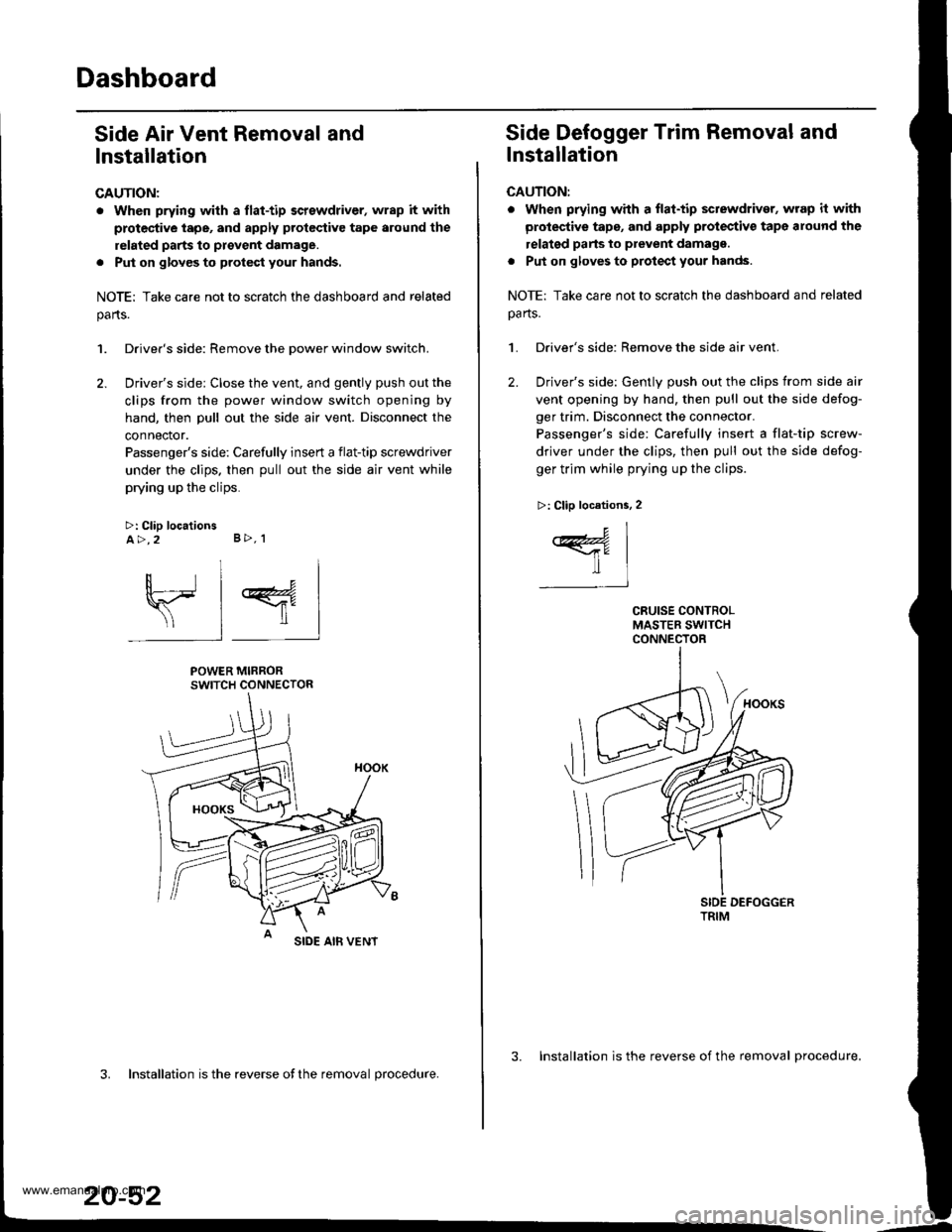
Side Air Vent Removal and
lnstallation
CAUTION:
. When prying with a flat-tip screwdriver, wrap it with
protec'tive tape, and apply protcctive tape around the
related parts to provent damage.
. Put on glov€s to protect your hands.
NOTE: Take care not to scratch the dashboard and related
parts.
1. Driver's side: Remove the Dower window switch.
2. Driver's side: Close the vent, and gently push out the
clips from the power window switch opening by
hand, then pull out the side air vent. Disconnect the
connector.
Passenger's side: Carefully insert a flat-tip screwdriver
under the clips. then pull out the side air vent while
prying up the clips.
>: Clip locationsA>,2 B>, 1
sl 4
POWER MIRRORSWITCH CONNECTOR
SIDE AIB VENT
3. Installation is the reverse ofthe removal procedure.
20-52
3. Installation is the reverse of the removal procedure.
Side Defogger Trim Removal and
lnstallation
CAUTION:
. when prying whh a flat-tip sctewdriver, wrap it with
protective tape, and apply protectiv€ tape around the
relatgd parts to prevent damagg.
. Put on gloves to protect your hands.
NOTE: Take care not to scratch the dashboard and related
oa rts.
1. Driver's side: Remove the side air vent.
2. Driver's side: Gently push out the clips from side air
vent opening by hand, then pull out the side defog-
ger trim. Disconnect the connector.
Passenger's side: Carefully insert a flat-tip screw-
driver under the clips, then pull out the side defog-
ger trim while prying up the clips.
>: Clip locations, 2
c1
ffil-t
TRIM
www.emanualpro.com
Page 1034 of 1395
Dashboard Removal and Installation
SRS components are located in this area. Review the SRS
component locations, precautions, and procedures in the
SRS section {24) before preforming repairs or service.
CAUTION:
. When prying with a flat-tip screwdriver, wrap h withprotective tap€, and apply protective tape around the
related parts to prevgnt damage.
. Put on gloves to prot€ct your hands.
NOTE:
. An assistant is helpful when removing and installing
the dashboard.
. Take care not to scratch the dashboard, bodv and
other related parts.
1.Make sure you have the anti-theft code for the
radio, then write down the frequencies for the
radio's preset buttons.
Disconnect the negative battery cable. and wait at
least three minutes before beginning work.
Removei
a Driver's dashboard lower cover and knee bolster(see page 20-48)
. Glove box (see page 20-49)
. Lower console cover and center pocket (A/T
model, see page 20-49)
. Center console and center upper pocket (M/T
model, see page 20-47)
. Center dashboard lower cover (see page 20-50)
. Power window switch (see page 20-51)
. Driver's side air vent (see page 20-52)
. Driver's side defogger trim (see page 20-52)
Disconnect the driver's airbag connector, and lower
the steering column (see section 17)
NOTE: To prevent damage to the steering column,
wrap it with a shop towel.
2.
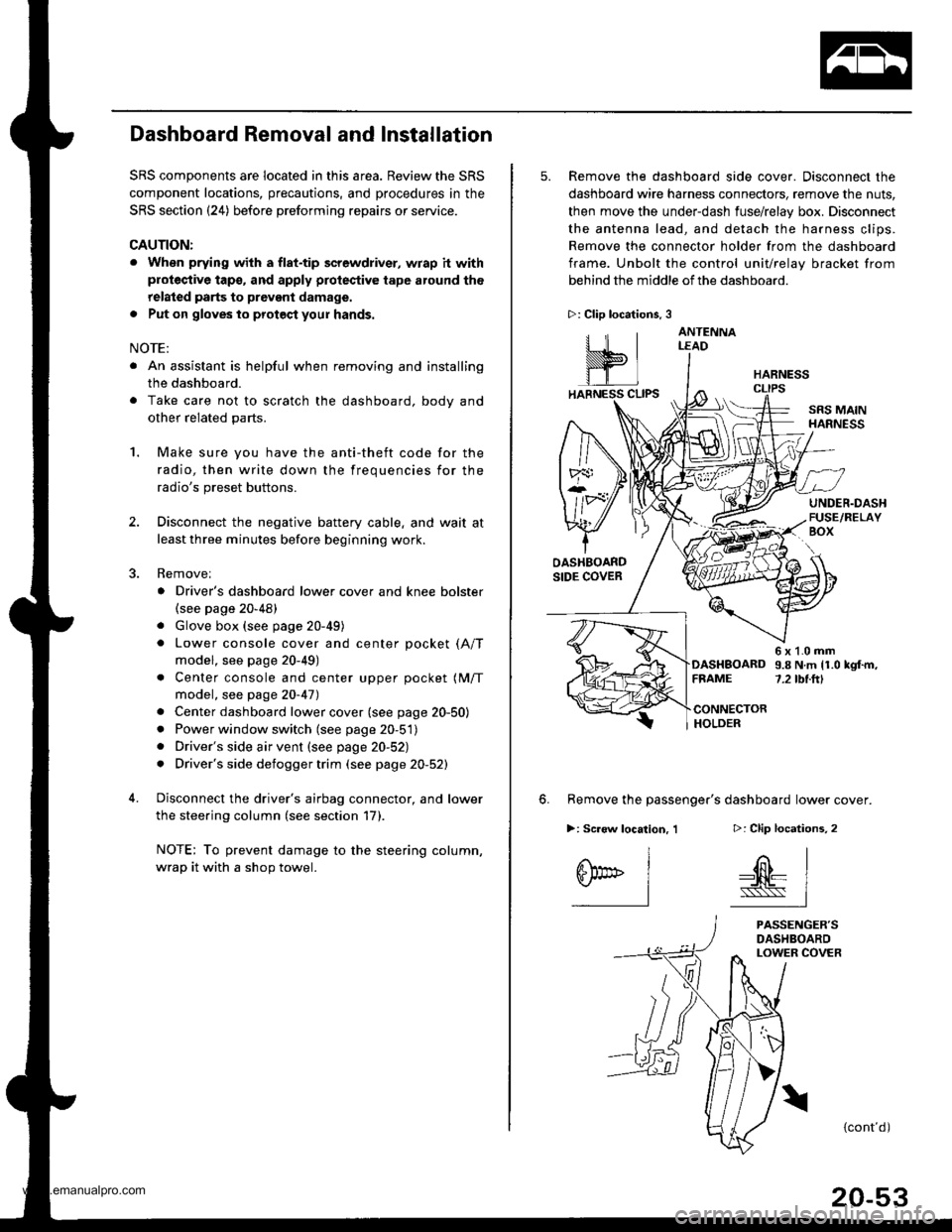
5. Remove the dashboard side cover. Disconnect the
dashboard wire harness connectors, remove the nuts,
then move the under-dash fuse/relay box. Disconnect
the antenna lead, and detach the harness clips.
Remove the connector holder from the dashboard
frame. Unbolt the control unit/relay bracket from
behind the middle of the dashboard.
HARNESS
6. Remove the passenger's dashboard lower cover.
D: Clip locations,
nl
-$t- Issj
I
ANTENNALEAD
>: Clip locations.
rttl
slllll
>: Scr€w location, 1
I
SF:oo I-l
SRS MAINHARNESS
UNDER.DASHFUSE/RELAYBOX
OASHBOARDSIDE COVER
6x1.0mm9.8Nm11.0kgf.m,7.2tbt.ftlDASHBOARDFFAME
CONNECTORHOLDER
PASSENGER'SDASHBOARDLOWER COVER
{cont'd)
www.emanualpro.com
Page 1084 of 1395
Wiper Arms and Washer Nozzles Adiustmenl
Wind3hield Wipor/Washer:
1, Adiust the wiper arms so that their park positions
match the illustration.
Viow from flont io roar
GLASS
2. Insert a tack into the washer nozzles. and
them so that they aim at positions A, A', B,
shown in the illustration.
adjust
and B'
Distance
^,J;-ll\
from center
line
from black
ceramic edge
A and A'3,$ mm (13.5 in.)287 mm (11.3 in.)
B and B'122 mm (4.80 in.)352 mm (13.9 in.)
Rear Window wipor/Washer:
Vi6w trom roar to lront
REARsPo[.-ER
C.nlar linoL
Align to the rear windowdefogger grid line.
Distance
ru"rrr. "i.
'_\from center
ltne
from black
ceramic edge
27 mm (1.1 in.)88 mm (3.5 in.)
20-103
www.emanualpro.com
Page 1094 of 1395
Component Location
lndex (cont'dl
SRS components are located in this area. Review the SRS component locations, precautions, and procedures in the SRS
section (24) before performing repairs or service.
BLOWER UNITReplacement, page 22-46Ovethaul, page 22 47
/alowen ruoronl
\Test, page 22-16 /
EVAPORATORFeplacement, page 22-48Overhaul, page 22,49
RECIRCULATIONCONTROL MOTORReplacement, page 22 42
HEATER UNITReplacement, page 22 50Overhaul, page 22 52
lest, pag.e 22 42
A/C FILIERReplacement. page 22-50VALVE CABLEAdjustment, page 22-53
RECIRCULATIONCONTROL SWITCH
a/c swtTcH
MODEMOTOR
REAR WINDOWDEFOGGERSwlTCHSee section 23Replacement, page 22-41Test, page 22-41MODE CONTROLDIAL
HEATER CONTROLPANELReplacement, page 22 46
swtTcH
22-4
CONTROL
www.emanualpro.com
Page 1130 of 1395
Troubleshooting
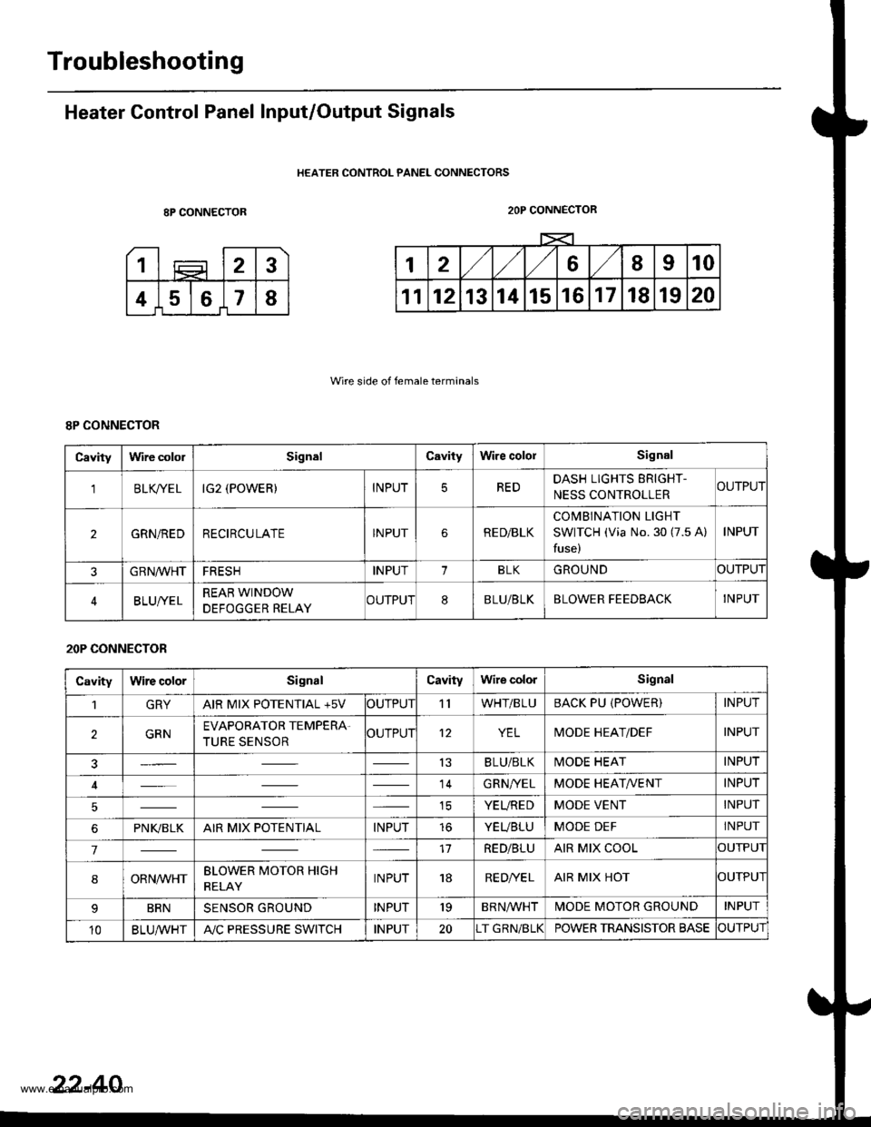
Heater Control Panel Input/Output Signals
HEATER CONTROL PANEL CONNECTORS
8P CONNECTOR
Wire side of female terminals
2OP CONNECTOR
8P CONNECTOR
Cavitylrvire cololSignalCavityWire cololSignal
'lBLK/TE LIG2 (POWER)INPUTREDDASH LIGHTS ERIGHT-
NESS CONTROLLERCUTPUT
2GRN/REDRECIRCULATEINPUTRE D/BLK
COMBINATION LIGHT
SWITCH (Via No. 30 (7.5 A)
fuse)
INPUT
GRN/VVHTFRESHINPUT1BLKGROUNDOUTPUT
BLUI/ELREAR WINDOW
DEFOGGER RELAYCUTPUT8BLU/BLKBLOWER FEEDBACKINPUT
20P CONNECTOR
CavityWire colorSignalCavityWire colorSignal
1GRYAIR MIX POTENTIAL +5VOUTPUT'llWHT/BLUBACK PU (POWER)INPUT
2GRNEVAPORATOR TEMPERA.
TURE SENSOROUTPUT12YELMODE HEAT/DEFINPUT
13BLU/BLKMODE HEATINPUT
14GRN/YELMODE HEAT/VENTINPUT
ICYEUREDMODE VENTINPUT
6PNI(BLKAIR MIX POTENTIALINPUTtoYEUBLUMODE DEFINPUT
717RED/BLUAIR MIX COOLOUTPUI
8ORNrur'HTBLOWER MOTOR HIGH
RELAYINPUT18RE D/VE LAIR MIX HOTOUTPUI
BRNSENSOR GROUNDINPUT'19BRNA/VHTIVIODE MOTOR GROUNDINPUT
10BLU,ryVHTA"/C PRESSURE SWITCHINPUT20T GRN/BLKPOWER TRANSISTOR BASECUTPUT
22-40
www.emanualpro.com
Page 1168 of 1395
Relay and Gontrol Unit Locations
Dashboard (cont'd)
HEATER CONTROL PANEL
REAR WINDOW DEFOGGER RELAY
WINDOW RELAY
-rj,r1 /-\,r1Iu lJ-JlJ r*t
23-8
INTEGRATEO CONTROL UNITTURN SIGNAL/HAZARD RELAY
www.emanualpro.com
Page 1176 of 1395
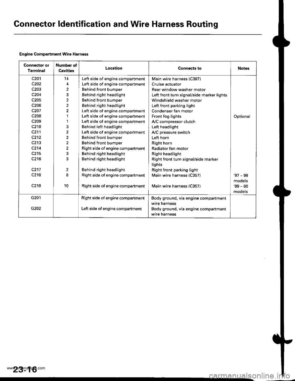
Gonnector ldentification and Wire Harness Routing
Engine Compartment Wire Harness
Connector ol
Terminal
Number of
CavitiesLocationConnects toNotes
c20'l
c202
c203
c204
c205
c206
c207
c208
c209
c210
c212
c213
c2't4
c215
c216
c217
c21A
c218
14
2
2
1'l
2
10
Left side of engine compartment
Left side of engine compartment
Behind front bumper
Behind right headlight
Behind front bumper
Behind right headlight
Left side of engine compartment
Left side of engine compartment
Left side of engine compartment
Behind left headlight
Left side of engine compartment
Behind front bumper
Behind front bumper
Right side of engine compartment
Behind right headlight
Behind right headlight
Behind right headlight
Right side of engine compartment
Right side of engine compadment
Main wire harness (C307)
Cruise actuator
Rear window washer motor
Left front turn signal/side marker lights
Windshield washer motor
Left front parking light
Condenser fan motor
Front fog lights
IVC compressor clutch
Left headlight
IVC pressure switch
Left horn
Right horn
Radiator fan motor
Right headlight
Right front turn signal/side marker
lights
Right front parking light
Main wire harness 1C357)
Main wire harness (C357)
Optional
'97 - 98
models'99 - 00
mooets
G201
G202
Right side of engine companment
Left side of engine compartment
Body ground, via engine compartment
wire harness
Body ground, via engine compartment
wire harness
23-16
www.emanualpro.com