Page 123 of 1395

Timing Belt
Removal
Replace the timing belt at 105,000 miles (168,000 km)
according to the maintenance schedule {normal condi-
tions/severe conditions). lf the vehicle is regularly driven
in either of the following conditions, replace the timing
belt at 60,000 miles (U.S.A.l 100.000 km (Canada).
- ln very high temperatures (over 110'F, 43"C).- In very low temperatures (under -20"F. -29"C).
Turn the crankshaft pu\ley so the No. 1 piston is at
top dead center (TDC).
Remove the guard bar and splash shield (see page
5-7 ).
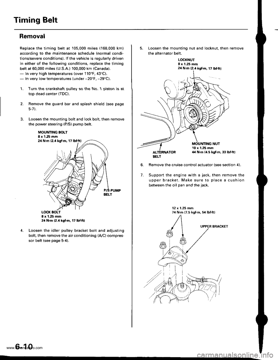
Loosen the mounting bolt and lock bolt. then remove
the power steering (P/S) pump belt.
MOUNNNG BOLT8 x 1.25 rnm
1.
2.
,l
4. Loosen the idler pulley bracket bolt and adjusting
bolt, then remove the air conditioning (lVC) compres
sor belt (see page 5-4).
6-10
24 N.m {2.4 kgt.m, 17 lbf.ftl
24 N.m 12.4 kgf.m, lt lbf.ftl
5. Loosen the mounting nut and locknut, then remove
the altefnator belt.
LOCKNUTI x 1.25 mm2a N.m 12.4 kgt m, 17 lblftl
6.
10 x 1,25 mm4,1 N.m (,1.5 kgt m, 33 lbtftl
Remove the cruise control actuator (see section 4).
Support the engine with a jack, then remove the
upper bracket. Make sure to place a cushion
between the oil Dan and the iack.
12 x 1.25 mm74 N.m (7.5 kgf m, 54 lbtftl
7.
BRACKET
AELT
www.emanualpro.com
Page 255 of 1395
c108
ffi
FfBLK//EL---ll -IREor/Ar -l
c107
ffi
|iTYEU€LX' I-rfnri-r --
c105{Canadal
r'fifl
fi'Iw|r/nE D. -'-l
T'TBt(ryEL -_-l
t lnrtsrr t]l
c105(usA)
F Irt
lslrl
filBLKry.L Ifu-,wHrcn[ ll]
ftl-wNr/sr't l]l
TaTtNanEc! ---l
c133
A
v
riaF.
jrr. IttInEoYEr, - l]l
c104
l1 2l
f -T;iE;;n ----
I ' WNT]FEDI L
c103
Ir zl
lrlBR,r tll
c134
c303
fil FEp/Bru ----l
NOTE: . Different wires with the same color have been given a number suffix to distinguish them (for example.
YEUBLK' and YEUBLK'� are not the same).
. O: Related to Fuel and Emissions Svstem.
. - Connector with male terminals (double outline): View from terminal side
- Connector with female terminals {single outline): View from wire side
c137
10
ffi
c109
ffi
l-!. IYEUBLK. ---l
1"1""' -
1 1-53
www.emanualpro.com
Page 362 of 1395
![HONDA CR-V 1997 RD1-RD3 / 1.G Workshop Manual
ldle Gontrol System
Alternator (ALT) FR Signal (contdl
98 - 00 modols:
ALT CONNECTOR (C1I}5I
4P
rH] Arr FllltwHr/REo)l3laF1
I JUMPER WIRE JUMPER+ WIRE
ECM/PCM CONNECTORS
Wire side of female termi HONDA CR-V 1997 RD1-RD3 / 1.G Workshop Manual
ldle Gontrol System
Alternator (ALT) FR Signal (contdl
98 - 00 modols:
ALT CONNECTOR (C1I}5I
4P
rH] Arr FllltwHr/REo)l3laF1
I JUMPER WIRE JUMPER+ WIRE
ECM/PCM CONNECTORS
Wire side of female termi](/manual-img/13/5778/w960_5778-361.png)
ldle Gontrol System
Alternator (ALT) FR Signal (cont'dl
'98 - 00 modols:
ALT CONNECTOR (C1I}5I
4P
rH] Arr Fl'l'ltwHr/REo)l3laF1
I JUMPER WIRE JUMPER+ WIRE
ECM/PCM CONNECTORS
Wire side of female terminals
ECM/PCM CONNECTOR C {31PI
Wire side of female terminals
Wire side of female terminals
ECM/PCM CONNECTOR C {31P}
": Canada
1 1-160
B (25P)
Insp€ction of ALT FR Signsl.
Check fo. a shon in th. wire {ALTF linel:1. Disconn6ct the 4P (3P)* con-nector from the ALT.2. Turn the ignition switch ON {ll).3. Measure voltage between ECM/PCM connector terminals C5and 820.Ch€ck for a sho.t in iho wirc lAlTF lino):1. Turn the ignition switch OFF.2. Disconnecl the negative bat,tery cable from the battery.3. Disconnect ECM,PCM connec-torC (31P).
4. Check for continuity betwoenbody ground and ECM/PCMconnector terminal c5.
ls there approx. 5 V7
Check the opcration of the ALT:1. Turn the ignitioo switch OFF.2. Reconnect rhe ALT 4P (3P)*connector to the ALT.3. Start the engine. Hold theengine at 3,000 rpm with noload (in Park or neutral) untilthe radiator lan comes on,then let it idle.4. Measure voltage between ECM/PCM connector terminals C5and 820.
Roprir lhort in tho wirc bstweentho ECM/PCM {Csl and the ALT.
Substitut. r known-good ECM/PCM and roch.ck. It Droscrib.dvoltage b now lvrilabls, .eplaccth. o.igin!l ECM/PCM.
Does the voltage decrease whenheadlights and rear defogger areturned on?ALT FR 3ignol is OK,
Chock lor an opon in tha wire (ALTF linel:1. Turn the ignition switch OFF.2. Disconnect the negative bat-tery cable from the battery.3. Disconnect ECM/PCM con-nector C (31P).4. Disconnect the 4P 13P)* con,nector from the ALT.5. Connect the ALT 4P {3P)* con-nector terminal No. 4 1No. 1)*to body ground with a jumper
6. Check for continuity betwe€nbody ground and ECM/PCMconnector terminal C5.
Rsprir opan wiro batw.en thoECM/PCM lcsl .nd th. ALT.ls there continuity?
AI.T F IWHT/REDI
ALT F {WHT/REDI
Wire side ot Iemale terminals
www.emanualpro.com
Page 371 of 1395

ldle Speed Setting
Inspoction/Adiustmont
37 modsl:
NOTE:
. Before setting the idle speed, check the following
items:- The MIL has not been reportsd on.- lgnition timing- Spark plugs
- Air cleaner- PCV system
. lcanada) Pull the parking brake lever up. Stan the
engine, then check that the headlights are off.
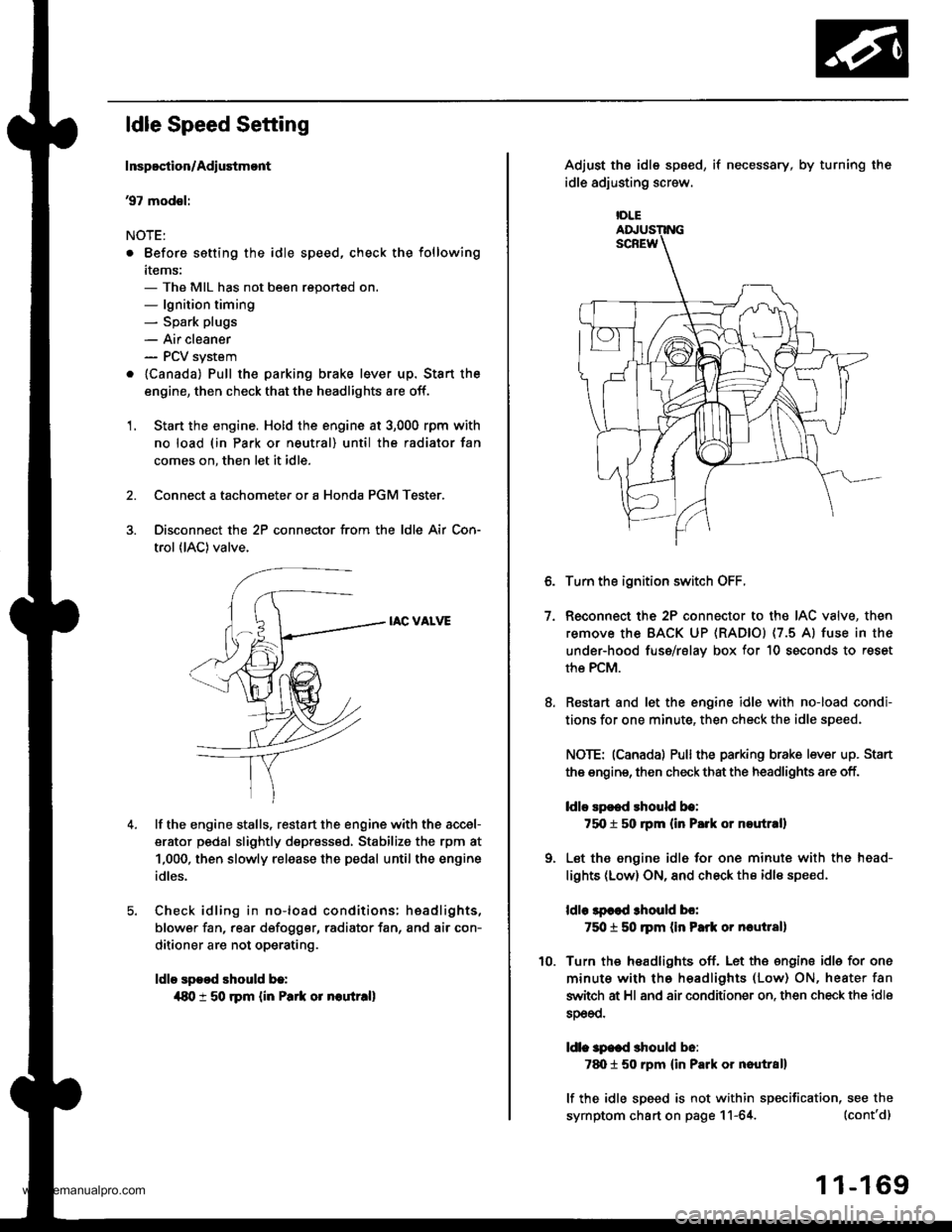
1. Start the engine. Hold the engine at 3,000 rpm with
no load (in Park or neutral) until the radiator fan
comes on, then let it idle.
Connect a tachometer or a Honda PGM Tester.
Disconnect the 2P connector from the ldle Air Con-
trol (lAC) valve.
IAC VALVE
lf the engine stalls, restart the engine with the accel-
erator pedal slightly depr6ss6d, Stabilize the rpm at
1,000, then slowly release the pedal until the engine
idles.
Check idling in no-load conditions: hsadlights,
blower fan, rear d€fogger, radiator fan, and air con-
ditioner are not operating.
ldle spood should b.:
{80 t 50 rpm {in Park or noutr.ll
IDLE
7.
Adjust the idle sp6ed,
idle adjusting screw.
if necessary, by turning the
Turn the ignition switch OFF.
Reconnect the 2P connector to the IAC valve, then
remove the BACK UP (RAD|Ol (7.5 Al fuse in the
under-hood fuse/rslav box for 10 seconds to reset
the PCM.
Restart and let the engine idle with no-load condi-
tions for one minute, then check the idle speed.
NOTE: (Canadal Pullthe parking brake lever up. Stan
the engine, then check that the headlights are off.
ldlo Ep€ed rhould be:
75O t 50 rpm (in P.rk or noutr.ll
Let the engine idl6 for one minute with the head-
lights (Low) ON, and check th€ idl€ speed.
ldle lpcod 3hould bo:
750 t 50 ]pm (in Park or nautlal)
Turn the headlights off. Let th€ engine idle for one
minute with the headlights (Low) ON, heater fan
switch at Hl and air conditioner on. then check the idle
sDeeo.
ldl. specd should b6:
7d) 1 50 rpm {in Park or nautral}
lf the idle speed is not within specification, see the
symptom chart on page 11-64. (cont'd)
1 1-169
www.emanualpro.com
Page 401 of 1395

Emission Control System
System Description
The emission control system includes, a Three Way
Catalytic Converter {TWC), Positive Crankcase Ventilation
(PCV) svstem and Evaporative Emission (€VAP) Control
system. The emission control system is designed to meet
federal and state emission standards.
Tailpipe Emission
Inspsction
!@ Do not smoke during this procsdura. Keep
any open tlame away from your work area.
1. Start the engine. Hold the engine at 3,000 rpm with
no load (in Park or neutral) until the radiator fan
comes on, then let it idle,
Connect a tachometer.
Check and, if necessary, adjust the idle speed, (see
page 11-169, 170).
Warm up and calibrate the CO meter according to the
meter manufacturer's instructions.
Check idle CO with the headlights, heater blower, rear
window defogger, cooling fan, and air conditioner off.
(Canada) Pull the parking brake lever up. Start the
engine, then check that the headlights are off.
CO meter should indicate 0.1% maximum.
4.
Three Way Catalytic Converter (TWCI
DsscriDtion
Three Way Catalytic Convertsr lTwcl:
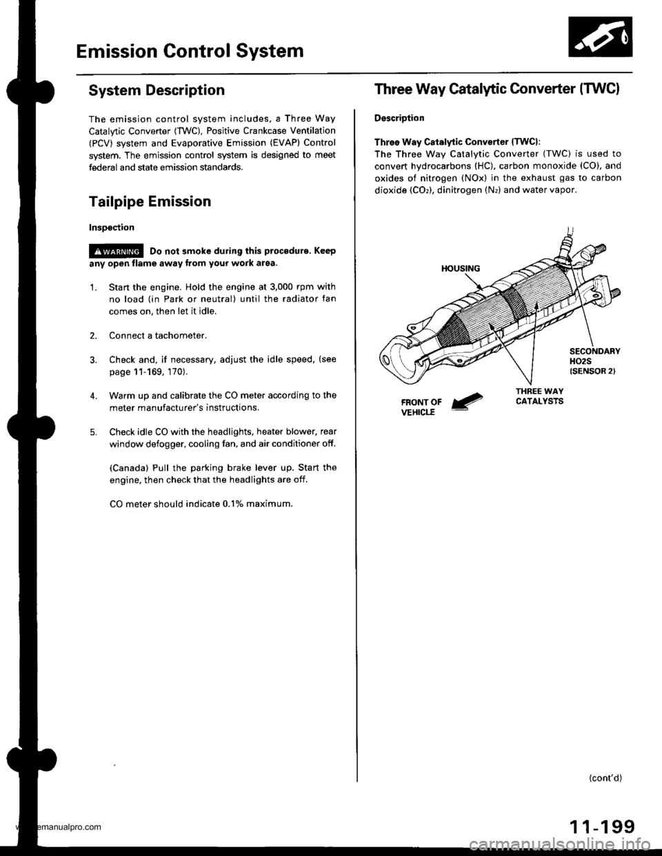
The Three wav Catalvtic Converter (TWC) is used to
convert hydrocarbons (HC), carbon monoxide (CO), and
oxides of nitrogen (NOx) in the exhaust gas to carbon
dioxide (COr), dinitrogen (Nr) and water vapor,
{cont'd)
1 1-199
www.emanualpro.com
Page 823 of 1395
![HONDA CR-V 1997 RD1-RD3 / 1.G Workshop Manual
Front Driveshafts
parts with solvent.
o *4@] :Thoroughly pack the inboard and outboard joints and both joint boots with the joint grease included in the
new driveshaft set.. The98 Canada model andal HONDA CR-V 1997 RD1-RD3 / 1.G Workshop Manual
Front Driveshafts
parts with solvent.
o *4@] :Thoroughly pack the inboard and outboard joints and both joint boots with the joint grease included in the
new driveshaft set.. The98 Canada model andal](/manual-img/13/5778/w960_5778-822.png)
Front Driveshafts
parts with solvent.
o *4@] :Thoroughly pack the inboard and outboard joints and both joint boots with the joint grease included in the
new driveshaft set.. The'98 Canada model andall '99 - 00 models use a TPE (Thermoplastic Polyester E lastomer) outboard joint boot.
Use the ear clamp type boot band in the outboard boot set.
Grease quantity:
Inboard Joint: All models 120 - 130 g (i1.2 - 4.6 oz)
Left inboard joint splines (Al: 0.5 - 1.0 g (0.018 - 0.035 oz)
Outboard Joint: '97 model and'98 USA model 130 - 140 g (4.6 -,1.9 oz)'98 Canada model and all '99 - 0O models 140 - 150 g 14.9 - 5.3 oz)
Reassembly
Note these items during reassembly
. Clean the disassembled parts with solvent, anddry them thoroughly with compressed air. Do not wash the rubber
INBOARO JOINT
SPIOERINBOARD BOOT
SET RINGReplace.
LEFT INBOAROJOINT
SPLINES: (Al-6rPack cavity with grease.
wtn grease.
BANDS
DYNAMIC DAMPER
STOP RINGReplace.
OUTBOARD BOOT
EAR CLAMPReplace.
ITPE)*I
-611
-/ Pack cavity with grease.
DOUELEReplace.BAND+'BAND*1
__G1Pack cavitywrtn grease.
OUTBOARD BOOT*'(RUBBERI
-GrjPack cavity*l: '98 Canada models, all '99-00models
*2: '97 - 98 models (except'98 Canada model)
16-8
wtrn grease.
www.emanualpro.com
Page 829 of 1395
Front Driveshafts
8. Fit the boot ends onto the driveshaft and outboard
lornt.
OUTBOARD BOOT fiPE)
OUTBOARD BOOT
OUTBOARD BOOT
Reassembly (cont'd)
Install the boot bands,
. For all '97 models and'98
step 13.
. For'98 Canada models andgo to step 10.
OUTBOARD JOINT
USA models, go to
all '99 - 00 models,
10. Set the ear clamp band by threading the tab into theholes of the band.
16-14
11. Close the ear portion of the band with a commercially
available boot band pincers KENT-MOORE J-35910 or
equivalent.
BOOT BAND PINCERSKENT.MOORE J-35910or equivalent
12.Check the clearance between the closed ear Dortionof the band, lf the clearance is not within the stan-dard, close the ear portion of the band further.
6.0 mm 10.24 in) MAX
3.0 mm {0.12 in} MAX
EAR PORTION
www.emanualpro.com
Page 932 of 1395
![HONDA CR-V 1997 RD1-RD3 / 1.G Workshop Manual
Inspection and Adjustment
Brake System Indicator
Circuit Diagram lNuLR.HorJDGNrT 0llSt!ITCHUNDEB.DASHFUSE]NEtAY BOIrllA Nl] 42 4!A
PAF�K NC BRA(E S\IICH
GBNiBEO
Io\lt j I ERAKE tuU 0 rEVEr 9!1 I(N
| HONDA CR-V 1997 RD1-RD3 / 1.G Workshop Manual
Inspection and Adjustment
Brake System Indicator
Circuit Diagram lNuLR.HorJDGNrT 0llSt!ITCHUNDEB.DASHFUSE]NEtAY BOIrllA Nl] 42 4!A
PAF�K NC BRA(E S\IICH
GBNiBEO
Io\lt j I ERAKE tuU 0 rEVEr 9!1 I(N
|](/manual-img/13/5778/w960_5778-931.png)
Inspection and Adjustment
Brake System Indicator
Circuit Diagram lNuLR.HorJDGNrT 0llSt!ITCHUNDEB.DASHFUSE]NEtAY BOIrllA Nl] 42 4!A
PAF�K NC BRA(E S\I'ICH
GBNiBEO
Io\lt j I ERAKE tuU 0 rEVEr 9!1 I(N
| oPt^r'f,'1 .r
BIKI-o-:G401
Parking Brake Switch Test
1. Remove the parking brake cover,
2. Disconnect the connector from the parking brakeswitch.
3. Check for continuity between the terminal and bodyground in each position according to the table.
Terminal
Lever Position \
Positive
TerminalBody Ground
Lever Up--o
Lever Down
NOTE (Canada): lf the parking brake switch is OK, butthe brake system indicator does not function, perform
the input test for the daytime running lights control unit(see section 23).
Brake Fluid Level Switch Test
1. Remove the reservoir cap. Check that the float
moves up and down freely; if it doesn't, replace the
reservoir cap assembly.
2. Check for continuity between the terminals in each
switch position according to the table.
- r9''r
Position12
FLOAT UP
FLOAT DOWNo
RESERVOIR CAP
GROUND
Switch contacts open atproper fluid level.
19-8
www.emanualpro.com