1997 HONDA CR-V Toe in
[x] Cancel search: Toe inPage 695 of 1395
oa;\,6
G)!o,
a@,6
@o(a
@(}
@a@@@@@@@6@@)@@@@@@@@@@@@@
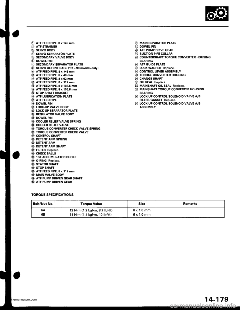
ATF FEED PIPE,8 x 145 mmATF STRAINERSERVO BODYSERVO SEPARATOR PLATESECONDARY VALVE EODYDOWEL PINSECONDARY SEPARATOR PLATESERVO DETENT BASE ('97 - 98 model3 onlylATF FEED PIP€, 8 x 145 mmATF FEED PIPE,8 x 40 mmATF FEED PIPE. 8 x 62 mmATF FEED PIPE.8 x 112 mmATF FEED PIPE, 8 x 192.5 mmATF FEEO PIPE. I x 105.8 mmSTOP SHAFT BRACKETATF LUBRICATION PLATEATF FEEO PIPEDOWEL PINLOCK-UP VALVE EODYLOCK-UP SEPARATOR PLATEREGULATOR VALVE BODYDOWEL PINCOOLER RELIEF VALVE SPRINGCOOLER RELIEF VALVETOROUE CONVERTER CHECK VALVE SPRINGTOROUE CONVERTER CHECK VALVECONTROL SHAFTOETENT ARM SPRINGOETENT ARMDETENT ARM SHAFTFILTER Replace.CHECK BALLSlST ACCUMULATOR CHOKEO"RING Replace.STATOR SHAFTSTOP SHAFTATF FEED PIPE, I x 112 mmMAIN VALVE BOOYATF PUMP DRIVEN GEAR SHAFTATF PUMP DRIVEN GEAR
TOROUE SPECIFICATIONS
MAIN SEPARATOR PLATEDOWEL PINATF PUMP DRIVE GEARSUCTION PIPE COLLARCOUNTERSHAFT TOROUE CONVERTER HOUSINGBEARINGATF GUIDE PLATELOCK WASHER Replace.CONTROL LEVER ASSEMBLYTOROUE CONVERTER HOUSINGCHANGE SHAFTOIL SEAL Reolace.MAINSHAFT OIL SEAL Reolace.MAINSHAFT TOROUE CONVERT€R HOUSINGBEARINGLOCK.UP CONTROL SOLENOID VALVE A/BFILTER/GASKET Replace.LOCK.UP CONTROL SOLENOID VALVE A/BASSEMBLY
@@@@@
@@@@@@@@
@
@
Bolt/Nut No.Torque ValugSizeRomarks
64
6B
12 N'm (1.2 kgf.m,8.7 lbf.ft)
14 N.m (1.4 kgf.m, 10 lbf.ft)
6x1.0mm
6x1.0mm
14-179
www.emanualpro.com
Page 760 of 1395
Transfer Assembly
18.
Reassembly (cont'dl
16. Apply Prussian Blue to both sides of the transfergear teeth lightly and evenly.
17.Rotate the companion flange in both directions until
the transfer gear rotates one full turn in both direc-
tions.
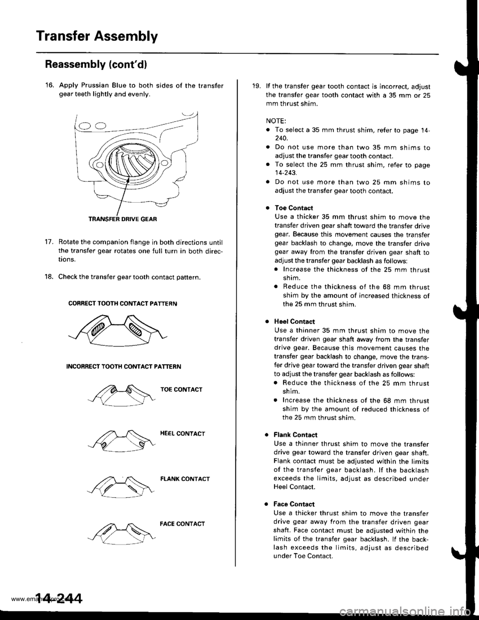
Check the transfer gear tooth contact pattern.
CORRECT TOOTH CONTACT PATTERN
NCONRECT TOOTH CONTACT PATTERN
TOE CONTACT
HEEL CONTACT
FLANK CONTACT
14-244
FACE CONTACT
19. lf the transfer gear tooth contact is incorrect, adjust
the transfer gear tooth contact with a 35 mm or 25
mm th rust shim.
NOTE:
. To select a 35 mm thrust shim, refer to page 14,240.
. Do not use more than two 35 mm shims to
adjust the transfer gear tooth contact.. To select the 25 mm thrust shim, refer to page
14-243.
. Do not use more than two 25 mm shims to
adjust the transfer gear tooth contact.
Toe Contact
Use a thicker 35 mm thrust shim to move the
transfer driven gear shaft toward the transfer drivegear. Because this movement causes the transfergear backlash to change, move the transfer drivegear away from the transfer driven gear shaft to
adjust the transfer gear backlash as follows:. Increase the thickness of the 25 mm thrust
shrm.
. Reduce the thickness of the 68 mm thrust
shim by the amount of increased thickness of
the 25 mm thrust shim.
Heel Contact
Use a thinner 35 mm thrust shim to move the
transfer driven gear shaft away from the transfer
drive gear. Because thjs movement causes the
transfer gear backlash to change, move the trans-
fer drive gear toward the transfer driven gear shaft
to adjust the transfer gear backlash as follows:. Reduce the thickness of the 25 mm thrust
shim.
. Increase the thickness of the 68 mm thrust
shim by the amount of reduced thickness ofthe 25 mm thrust shim.
Flank Contaqt
Use a thinner thrust shim to move the transfer
drive gear toward the transfer driven gear shaft.Flank contact must be adjusted within the limits
of the transfer gear backlash. lf the backlash
exceeds the limits, adjust as described underHeel Contact.
Face Contaqt
Use a thicker thrust shim to move the transfer
drive gear away from the transfer driven gear
shaft. Face contact must be adjusted within the
limits of the transfer gear backlash. lf the back-
lash exceeds the limits, adjust as described
under Toe Contact.
www.emanualpro.com
Page 798 of 1395
Description
Hydraulic Flow (cont'dl
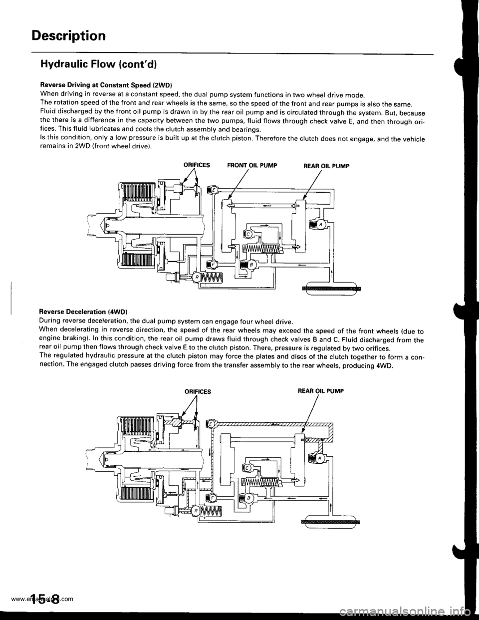
Reverse Driving at Constant Speed l2WD)when driving in reverse at a constant speed, the dual pump system functions in two wheel drive mode.The rotation speed of the front and rear wheels is the same, so the speed of the front and rear pumps is also the same,Fluid discharged by the front oil pump is drawn in by the rear oil pump and is circulated through the system. But, becausethe there is a difference in the capacity between the two pumps, fluid flows through check valve E, and then through ori-Iices. This fluid lubricates and cools the clutch assembly and bearings.ls this condition, only a low pressure is built up at the clutch piston. Therefore the clutch does not engage, and the vehicleremains in 2WD (front wheel drive).
Reverse Deceleration l/tWDl
During reverse deceleration, the dual pump system can engage four wheel drive.When decelerating in reverse direction, the speed of the rear wheels may exceed the speed of the front wheels (due toengine braking). In this condition, the rear oil pump draws fluid through check valves B and C. Fluid discharged from therear oil pump then flows through check valve E to the clutch piston. There, pressure is regulated by two orifices.The regulated hydraulic pressure at the clutch piston may force the plates and discs of the clutch together to form a con,nection. The engaged clutch passes driving force from the transfer assembly to the rear wheels, producing 4WD.
oRtFtcEsREAR OIL PUMP
www.emanualpro.com
Page 898 of 1395
't 4.
15.
Center the steering rack within its stroke.
Install the steering joint, and reconnect the steering
shaft and pinion shaft.
NOTE: Make sure the steering joint is connected as
follows.
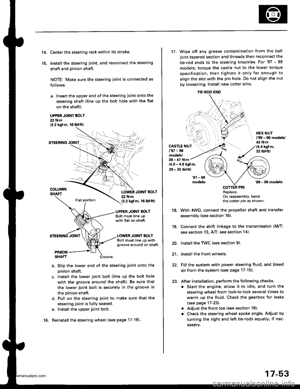
a. Insen the upper end of the steering joint onto the
steering shaft (line up the bolt hole with the flat
on the shaft).
UPPER JOINT BOLT22 N.m12.2 kgf.m, 16lbl.ft,
STEERING JOINT
COLUMNSHAFTLOWER JOINT BOLT22 N.m12.2 kgf.m, 16lbtftl
UPPER JOINT BOLTBolt must line upwith tlat on shatt.
LOWER JOINT BOLTBolt must line up withgroove around on shaft.
PINIONSHAFT
b, Slip the lower end of the steering ioint onto the
pinion shaft.
c. Install the lower joint bolt (line up the bolt hole
with ths groove around the shaft). Be sure that
the lower joint bolt is securely in the groove in
the pinion shaft.
d. Pull on the steering joint to make sure that the
steering joint is fully seated.
e, Install the upper joint bolt,
Reinstall the steering wheel {see page'17-19).16.
17-53
17. Wipe off any grease contamination trom the ball
joint tapered section and threads then reconnect the
tie-rod ends to the steering knuckles. For'97 - 98
models; torque the castle nut to the lower torque
specification, then tighten it only far enough to
align the slot with the pin hole. Do not align the nut
by loosening. Install new cotter pins.
CAST1T NUT(9t - 98modol!)
HEX NUTl'g!t - 00 modeb)il:l N.m14.4 ksl.m,32 tbf.f0
39 - iU N'm
lil.o - 4.8 kgl.m,
29 - 35 tbf.ftl
18.
19.
20.
21.
22.
23.
'99 - lD modeb:
COTTER PINRePlace.on reassembly, bendthe cotter Pin as shown.
With 4WD, connect the propeller shaft and transfer
assembly (see section 16).
Connect the shift linkage to the transmission (M/T:
see section 13, A,/T; see section 14).
Installthe Twc (see section 91.
lnstall the front wheels,
Fill the system with power steering fluid, and bleed
air from the system (see page 17-15).
After installation. perform the following checks.
. Start the engine, allow it to idle, and turn the
steering wheel from lock-to-lock several times to
warm up the fluid. Check the gearbox for leaks
(see page 17-23).
. Adjust the front toe (s€e section 18).
. Check the steering wheel spoke angl€. Adjust by
turning the right and left tie-rods equally, if nec-
essary.
TIE.ROO END
www.emanualpro.com
Page 899 of 1395
Suspension
Special Tools ............. 18-2
Component Locations
lndex ................ ...... 18-3
Wheel Alignment
Service lnformation ......................,.. 18-4
Camber .................. 18-4
Caster ............... ...... 18-5
Front Toe Inspection/
Adiustment ........ 18-5
Rear Toe Inspection/
Adiustment ........ 18-6
Turning Angle Inspection/
Adiustment ........ 18-6
Wheel/Hub Inspection
Bearing End Play .......................,...... 18-7
Wheel Runout ....... 18-7
Front Suspension
Suspension Arms Replacement ..... 18-8
Knuckle/Hub Replacement ............. 18-9
Lower Ball Joint Replacement ....... 18-15
Ball Joint Boot Replacement .......... 18-16
Front Damper
Removal ................. 18-16
Disassembly/lnspection .................. 18-1 7
Reassembly ........... 18-18
lnstallation ............. 18-18
Rear Suspension
Suspension Arms Replacement ..... 18-19
Hub Bearing Unit Replacement ...... 18-20
Upper Arm Bushing
Replacement ..... 18-23
Rear Damper
Removal ................. 18-23
Disassembly/1nspection .................. 18-24
Reassembly ........... 18-25
lnstallation ............. 18-25
www.emanualpro.com
Page 902 of 1395
Wheel Alignment
Caster
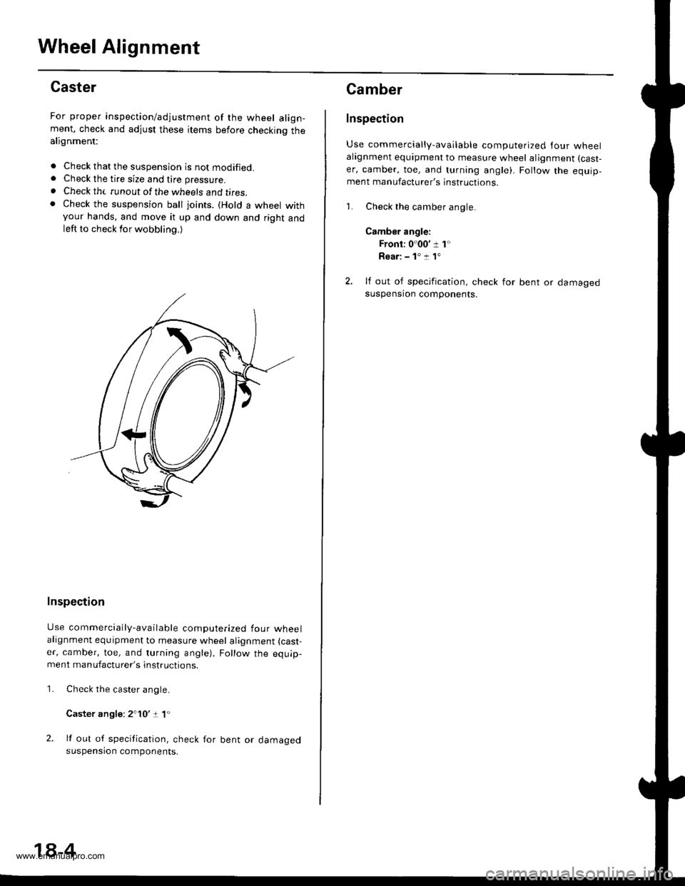
For proper inspection/adjustment of the wheel align-ment, check and adjust these items before checkinq thealignment:
. Check that the suspension is not modified.. Check the tire size and tire pressure.
. Check th( runout of the wheels and t;res,. Check the suspension ball joints. (Hold a wheel withyour hands, and move it up and down and right andleft to check for wobbling.)
Inspection
Use commercially-available computerized four wheelalignment equipment to measure wheel alignment (cast-
er, camber, toe, and turning angle). Follow the equip-ment manufacturer's instructions.
Check the caster angle.
Caster angle: 2'10':t 1"
lf out of specification, check for bent or damagedsuspension components.
1.
18-4
Camber
Inspection
Use commercially-available computerized lour wheelalagnment equipment to measure wheel alignment (cast,
er, camber, toe, and turning angle). Follow the equip,ment manufacturer's instructions.
1. Check the camber angle.
Camber angle:
Front: 0'00' 1 1"
Rear: - 1' :! 1"
2. lf out of specification, check for bent or damagedsuspensron components.
www.emanualpro.com
Page 903 of 1395
Front Toe Inspection/Adjustment
Use commercially-available computerized four wheel
alignment equipment to measure wheel alignment (caster,
camber, toe, and turning angle). Follow the equipment
manufacturer's instructions,
3.
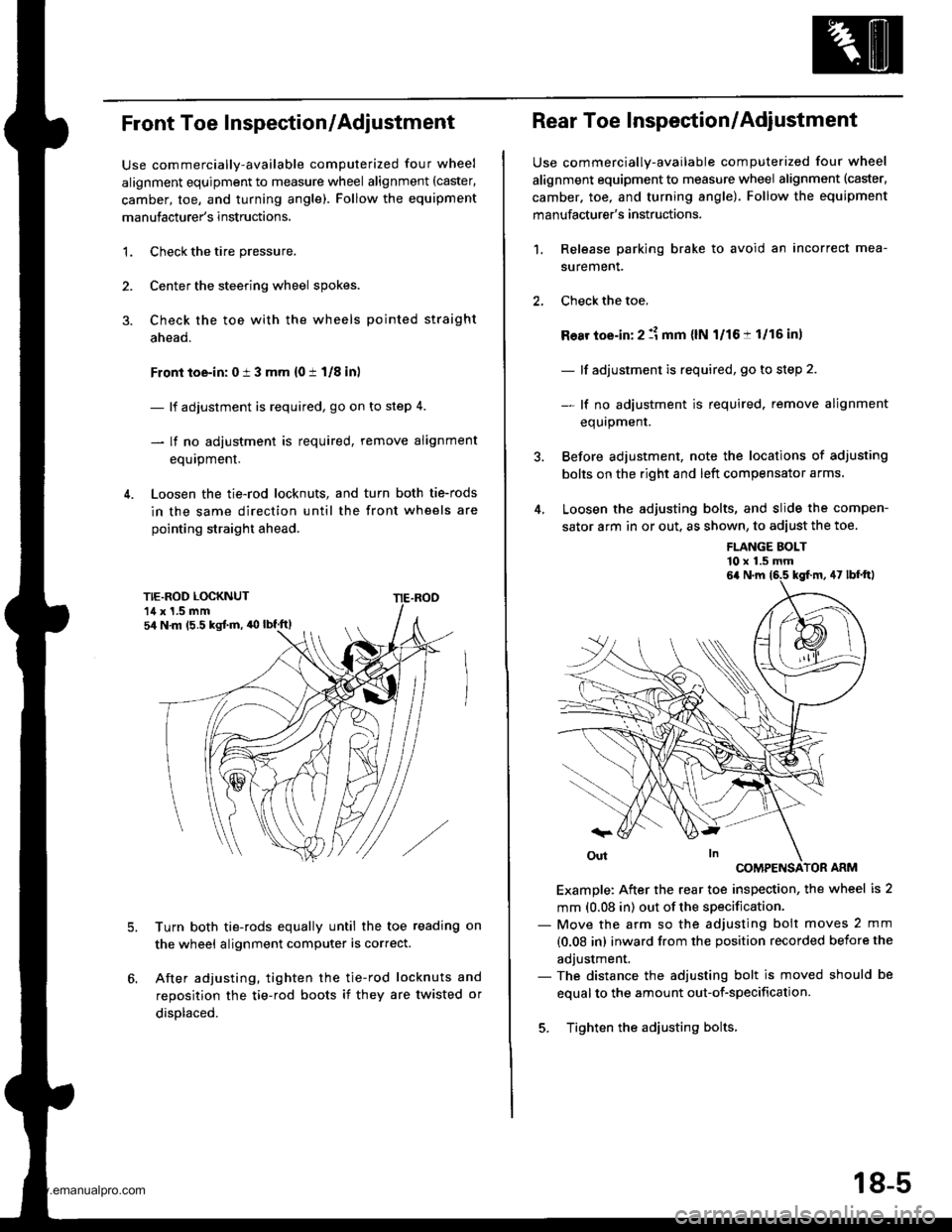
1.Check the tire pressure.
Center the steering wheel spokes.
Check the toe with the wheels pointed straight
ahead.
Front toe-in: 0 i 3 mm {0 t 1/8 inl
- lf adjustment is required, go on to step 4.
- lf no adjustment is required, remove alignment
equipment.
Loosen the tie-rod locknuts, and turn both tie-rods
in the same direction until the front wheels are
pointing straight ahead.
5.Turn both tie-rods equally until the toe reading on
the wheel alignment computer is correct.
After adjusting, tighten the tie-rod locknuts and
reposition the tie-rod boots if they are twisted or
displaced.
sir N m (5.5 kgJ.m, 'O lbf.ft)
Rear Toe Inspection/Adjustment
Use commercially-available computerized four wheel
alignment equipment to measure wheel alignment (caster,
camber. toe, and turning angle). Follow the equipment
manufacturer's instructions.
Release parking brake to avoid an incorrect mea-
surement.
Check the toe.
Ro8r toe-in: 2 :1 mm {lN l/16:t 1/16 in,
- lf adjustment is required, go to step 2.
- lf no adiustment is required. remove alignment
equrpmenr.
Before adjustment, note the locations of adjusting
bolts on the right and left compensator arms.
Loosen the adjusting bolts, and slide the compen-
sator arm in or out. as shown, to adiust the toe.
1.
FLANGE BOLT'10 x 1.5 mm
COMPENSATOR ARM
Example: After the rear toe inspection, the wheel is 2
mm (0.08 in) out of the specification.- Move the arm so the adjusting bolt moves 2 mm
{0.08 in) inward from the position recorded before the
adjustment.- The distance the adjusting bolt is moved should be
equal to the amount out-of-specification.
5. Tighten the adjusting bolts.
6a N.m 16.5 kgf.m, 47 lbf'ftl
18-5
www.emanualpro.com
Page 904 of 1395
Wheel Alignment
Turning Angle Inspection
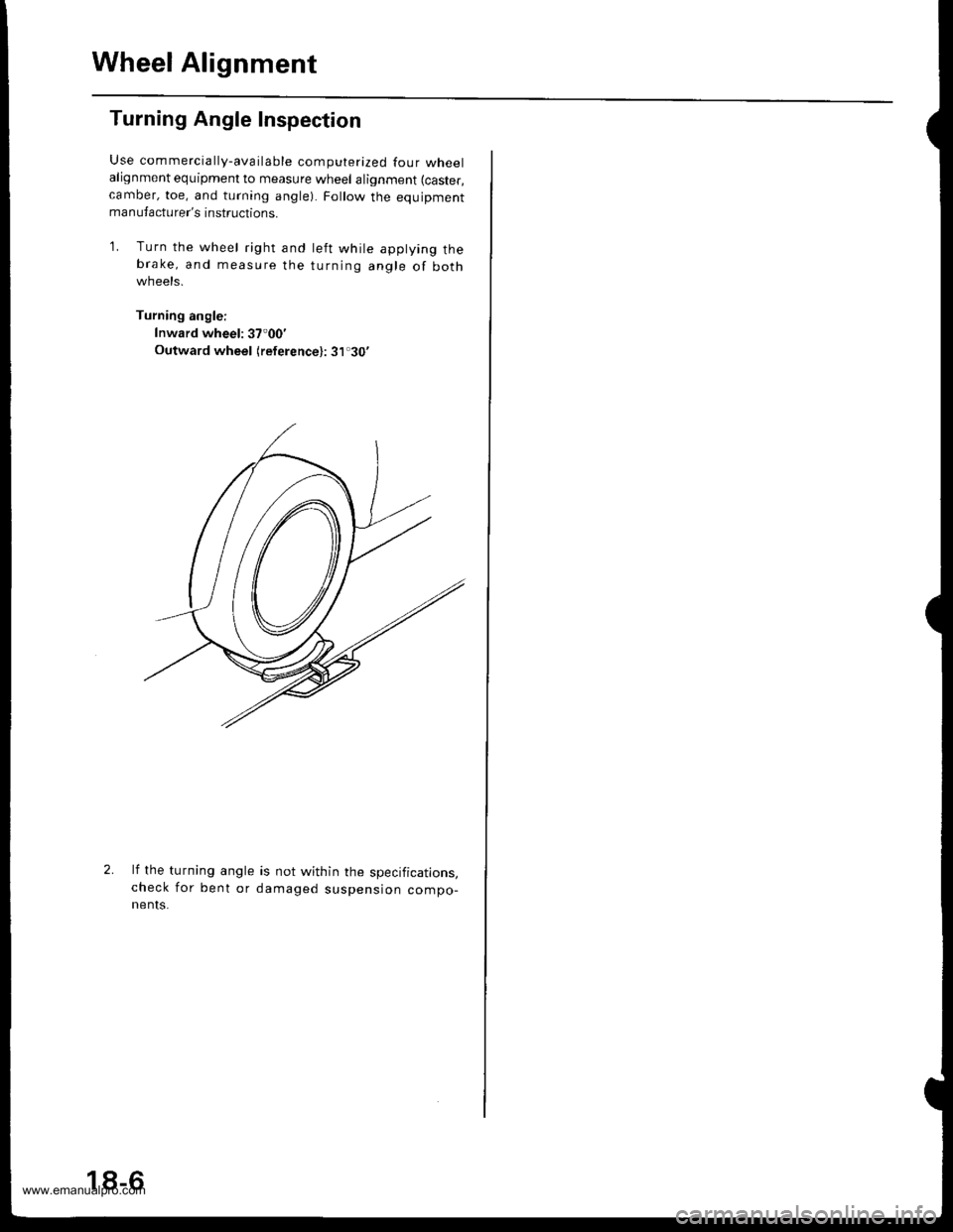
Use commercially-available computerized four wheelalignment equipment to measure wheel alignment (caster,
camber, toe, and turning angle). Follow the equipmentmanufacturer's instructions.
1. Turn the wheel right and left while applying thebrake, and measure the turning angle of bothwneets.
Turning angle:
Inward wheel: 37.00'
Outward wheel lreference): 31.30'
2.lf the turning angle
check for be nt or
nenIs.
is not within the specifications,
damaged suspension compo-
18-6
www.emanualpro.com