Page 156 of 1395
Pistons and Crankshaft
Removal (cont'dl
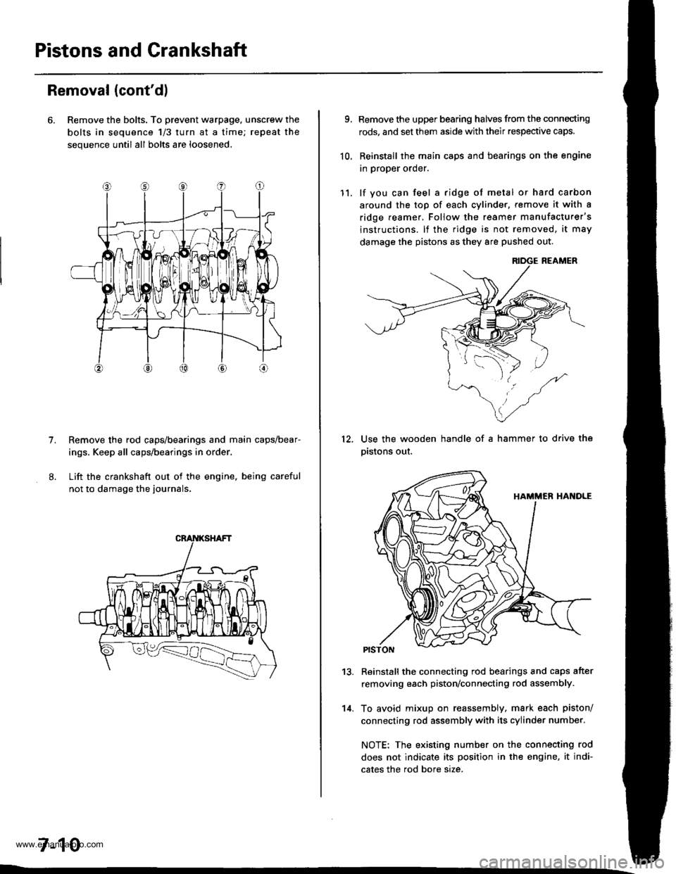
6. Remove the bolts. To prevent warpage, unscrew the
bolts in sequence 1/3 turn at a time; repeat the
sequence until all bolts are loosened.
Remove the rod caps/bearings and main caps/bear-
ings, Keep all caps/bearings in order
Lift the crankshaft out of the engine. being careful
not to damage the journals.
7.
7-10
9.
10.
Remove the upper bearing halves from the connecting
rods, and set them aside with their respective caps.
Reinstall the main caps and bearings on the engine
in proper order.
lf you can feel a ridge of metal or hard carbon
around the top of each cvlinder, remove it with a
ridge reamer. Follow the reamer manufacturer's
instructions. lf the ridge is not removed, it may
damage the pistons as they 8re pushed out.
12.
11.
14.
Use the wooden handle of a hammer to drive the
pistons out.
13.Reinstall the connecting rod bearings and caps after
removing each piston/connecting rod assembly.
To avoid mixup on reassembly, mark each piston/
connecting rod assembly with its cylinder number.
NOTE: The existing number on the connecting rod
does not indicate its position in the engine, it indi-
cates the rod bore size.
www.emanualpro.com
Page 166 of 1395
PistonsCrankshaft
Installation
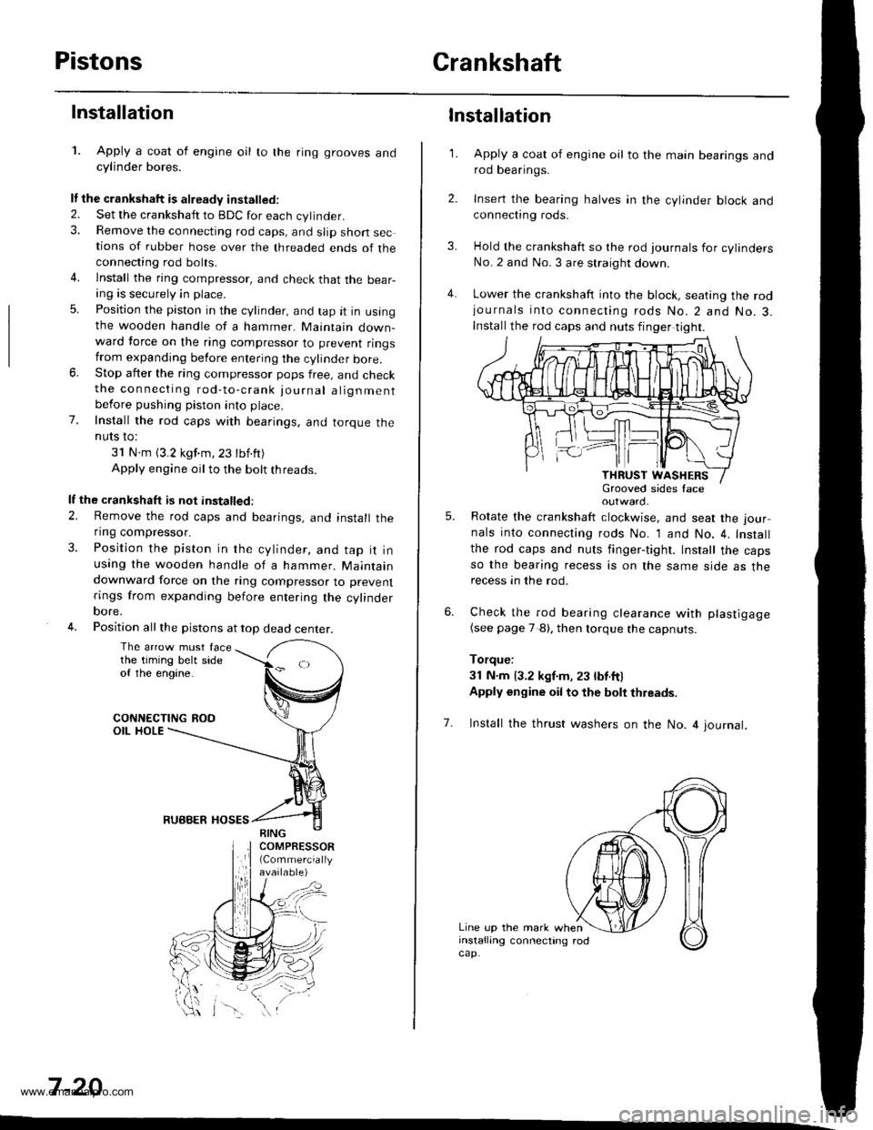
1. Apply a coat of engine oil to the ring grooves andcylinder bores.
It the crankshaft is already installed.
2. Set the crankshatt to BDC for each cylinder.3. Remove the connecting rod caps, and slip short sections of rubber hose over the threaded ends of theconnecting rod bolts.
4. lnstall the ring compressor, and check that the bear-ang is securely in place.
5. Position the piston in the cylinder, and tap it in usingthe wooden handle of a hammer. Maintain down-ward force on the ring compressor to prevent ringstrom expanding before entering the cylinder bore.6. Stop after the ring compressor pops free, and checkthe connecting rod-to-crank journal alignmentbefore pushing piston into place.
7. Install the rod caps with bearings, and torque theNUIS IO:
31 N.m (3.2 kgf.m,23 tbf.ft)
Apply engine oil to the bolt threads.
lf the crankshaft is not installed:
2. Remove the rod caps and bearings, and install theflng compressor.
3. Position the piston in the cylinder, and tap it inusing the wooden handle of a hammer. Maintaindownward force on the ring compressor to prevent
rings from expanding before entering the cylinderoore,
4. Position all the pistons at top dead center.
The arrow must facethe timing belt sideof the engine.
CONNECTING ROOOIL HOLE
RUBBER HOSES
7 -20
\-\
3.
4.
1.
6.
Installation
Apply a coat of engine oil to the main bearings androd bearings.
Insert the bearing halves in the cylinder block andconnect|ng rods.
Hold the crankshaft so the rod journals for cylindersNo.2 and No. 3 are straight down.
Lower the crankshaft into the block, seating the rodjournals into connecting rods No.2 and No.3.Install the rod caps and nuts finger tight.
outward.
Rotate the crankshaft clockwise, and seat the jour
nals into connecting rods No. 1 and No. 4, Install
the rod caps and nuts finger-tight. Install the capsso the bearing recess is on the same side as therecess an the rod.
Check the rod bearing clearance with plastigage(see page 7 8). then lorque the capnuts.
Torque:
3l N.m 13.2 kgf.m, 23 lbt.ftl
Apply engine oil to the bolt thleads.
5.
7. Install the thrust washers on the No. 4 journal.
Line up the mark wheninstalling connecting rodcap.
www.emanualpro.com
Page 167 of 1395
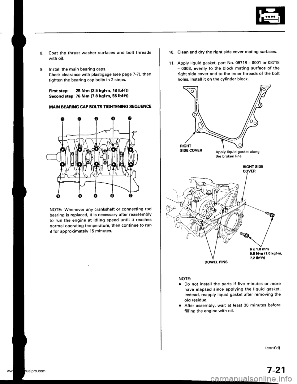
Coat the thrust washer surtaces and bolt threads
with oil.
Installthe main bearing caps.
Check clearance with plastigage (see page 7-7), then
tighten the bearing cap bolts in 2 steps.
First slsp: 25 N.m {2.5 kgf'm, 18 lbf'ft}
Sscond step: 76 N'm (7.8 kgf'm. 56 lbf'ft)
MAIN BEARING CAP BOLTS TIGHTENING SEOUENCE
NOTE: Whenever any crankshaft or connecting rod
bearing is replaced, it is necessary after reassembly
to run the engine at idling speed until it reaches
normal operating temperature, then continue to run
it for approximatelY 15 minutes.
10.Clean and dry the right side cover mating surfaces.
Apply liquid gasket, part No. 08718 - 0001 or 08718
- 0003, evenly to the block mating surface of the
right side cover and to the inner threads of the bolt
holes. Install it on the cylind€r block
11,
6x1.0mm9.E N.m {1.0 kgt m,7.2 tbf.ft)
NOTE:
. Do not install the parts if five minutes or more
have elapsed since applying the liquid gasket.
Instead, reapply liquid gasket after removing the
old residue.
. After assembly, wait at least 30 minutes before
filling the engine with oil.
(cont'dl
7-21
RIGHT SIDE
OOWEL PINS
www.emanualpro.com
Page 439 of 1395
Release Bearing
lnstallation
NOTE: Use only Super High Temp Urea Grease (P/N
08798 - 9002).
1. With the release fork slid bet\iveen the release bear-
ing pawls. install the release bearing on the main-
shaft while inserting the release tork through the
hole in the clutch housing.
lPlN 08798 - 9002)0.,1- 1.0 I (0.01 - 0 04 ozl
(P/N 087989002)
(P/N 08798 9002)
1.0 - 1.6 g
{0.0,1 - 0,06 ozl
-6.l(P/N 08798 -
r iz]))
| (,4\1t1t
/\[wRELEASEFORKBOOT
Align the detent of the release fork with the release
fork bolt, then press the release fork over the
release fork bolt sequarelv.
12-12
3. Move the release lork right and left to make sure
that it tits properly against the release bear'rng. and
that the release bearing slides smoothlY.
Install the release tork boot; make sure the boot
seals around the release fork and clutch housing.
4.
www.emanualpro.com
Page 440 of 1395
Manual Transmission
Diff€rential
lndex ...................... ......... 13-38
Backlash Inspestion ..,....,.,.....................,......, 13-38
Final Driven Gear Replacement .................... 13-39
Tapered Roller BearingReplacement ............. 13-39
Bearing Outer Race Replacement ......,.,........ 13-i10
Tapered Roller Bearing PreloadAdiustment ............... 13-il1
Oil Seal Reolacement .................................... 13-/l:}
Transfer Assembly
lllustrated Index ............. 13-il4
Inspection ..,....,.,......,...... 13-46
Disassembly ................... 13-47
Transfer Drive Gear BearingReplacement ...,..................,....................... 13-ilg
Transfer Driven Gear Shaft BearingReplacement .............................................. 13-ilg
Transfer Shaft Disassembly/Reassembly .............. 13-50
Transler Cover A Bearing Outer RaceRep1acement.........,.,.,..........,....,...,.........,., 13-50
Transter Housing Bearing Outer RaceReD1acement.............................................. 13-51
Reassembly ..-............,... 13-52
Mainshaft Bearing/Oil Seal
Beplacement .................. 13-62
Countershaft Bearing
Replacement .,,.,.,., ..,...... 13-63
Mainshaft Thrust Clearance
Adiustment .................... 13-6,1
Transmission Assembly
Reassembly .,.,.,.,..,.,....,., 13-67
fnstaffation .,.,.............,... 13-72
Gearshift Mechanism
Overhaul ................ .........13-17
www.emanualpro.com
Page 441 of 1395
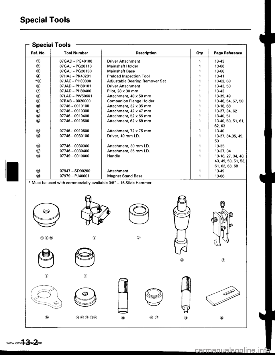
Special Tools
ll
Ref. No. I Tool NumberDsscriptionOty I Page Roterence
o
o,6)
@-o
\9'
a
@6r
@
o
@
@
@
@
@
@
@
@
@
07GAD - PG40100
07GAJ - PG20110
07GAJ - PG20130
07HAJ - PK40201
07JAC - PH80000
07JAD - PH80101
07JAD - PH80400
07LAD - PW50601
07RAB - 0020000
07746 - 0010100
07746 - 0010300
07746 - 0010400
07746 - 0010500
07746 - 0010600
07746 - 0030100
07746 - 0030300
07746 - 0030400
07749 - 0010000
07947 - SD90200
07979 - PJ40001
Driver Attachment
Mainshaft Holder
Mainshaft Base
Preload Inspection Tool
Adjustable Bearing Remover Set
Driver Attachment
Pilot, 28 x 30 mm
Attachment, 40 x 50 mm
Companion Flange Holder
Attachment,32 x 35 mm
Attachment, 42 x 47 mm
Attachment, 52 x 55 mm
Attachment, 62 x 68 mm
Attachment, 72 x 75 mm
Driver, 40 mm l.D.
Attachment. 30 mm l.D.
Attachment, 35 mm l.D.
Handle
Attachment
Magnet Stand Base
1
1
1'l
1
1
1
1
1
1'I
1
1
1
1
13-43
13-66
13-66
13-41
13-62. 63
13-43, 53
13-43
13-39, 49
13-48,54,57,58
13-18, 68
13-27,34, 62
13-40. 51't3-40, 50. 51, 61,
oz, oJ
13-40
13-27 ,34,35, 49,
tJ-5C
13-27,34
13-14,27.34, 40,
43, 49, 50, 51, 53,
61,62,63,68'13-49
13-66
* Must be used with commercially available 3/8" - 16 Slide Hammer.
o@(9ta\
oG)
,d,(oo@(9(}@o@
.A IAa 5-z
Special Tools
www.emanualpro.com
Page 450 of 1395
25. Remove the transmission mounting bolts and the
rear engine mounting bolts.
REAR ENGINE MOUNTING BOLTSReplace.
TRANSMISSION
Pull the transmission away from the engine until it
clears the mainshaft, then lower it on the transmis-
sion jack.
NOTE: Take care not to bend the clutch line.
Remove the starter motor and hose clamp from the
transmission housing.
STARTERMOTOR
28. Remove the release tork boot. release bearing, and
release fork from the clutch housing
RELEASEBEANING
13-1 1
www.emanualpro.com
Page 451 of 1395
Transmission Assembly
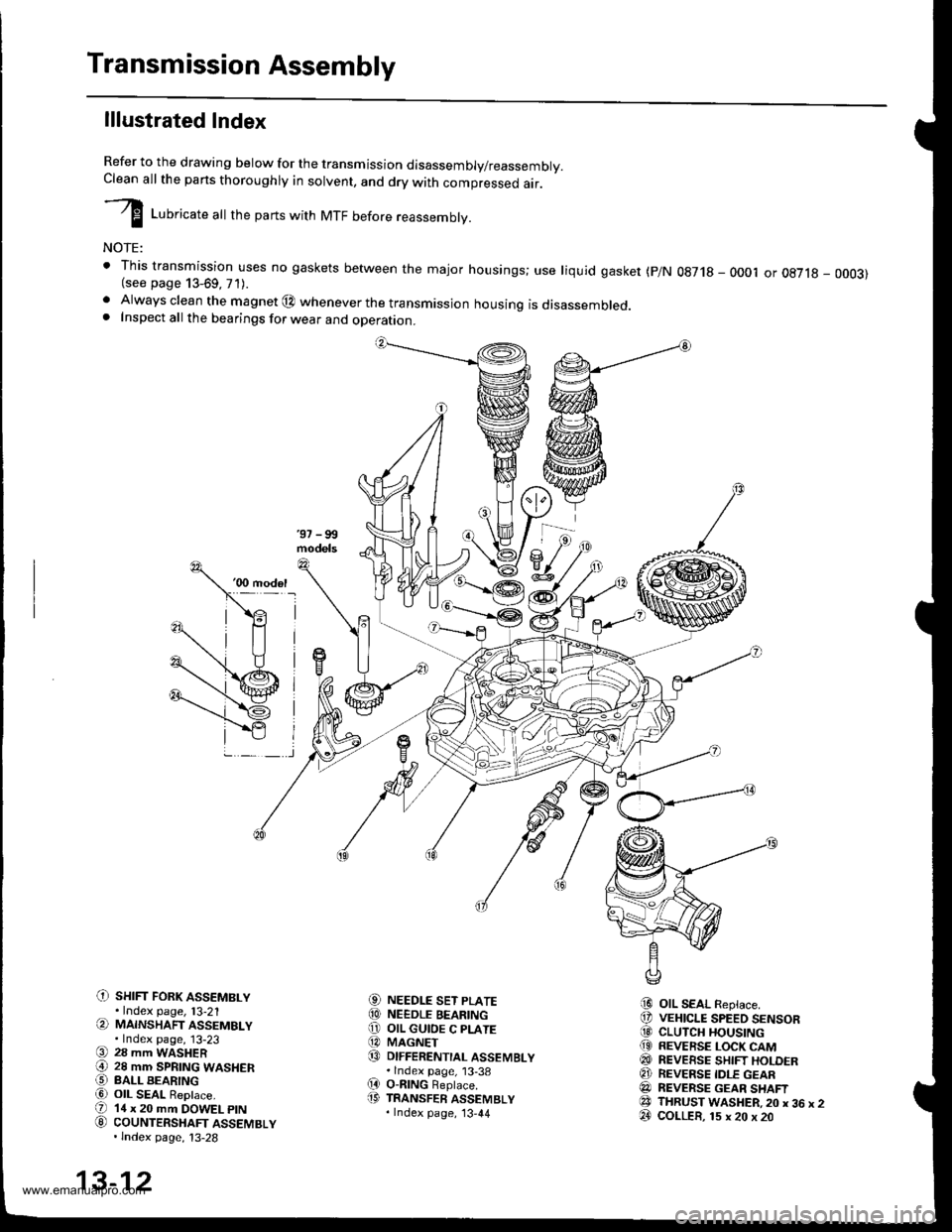
lllustrated Index
Refer to the drawing below for the transmission disassembly/reassembly.Clean all the pans thoroughly in solvent, and drv with comoressed air.
I LuUri""r" utt the parts with MTF before reassembly.
NOTE:
t This transmission uses no gaskets between the major housings; use liquid gasket (p/N 0g718 - 0001 or oE7l8 - 0003)(see page 13-69, 71).. Always clean the magnet @ whenever the transmissjon housing is disassembled.. Inspect all the bearings for wear and operation.
C) sHrFr FoRK ASSEMBLY.Index page, l3-21(a MAINSHAFT ASSEMBLY.Index page, 13-23(9 28 mm WASHER€) 28 mm SPRTNG WASHERO BALL BEARINGa6) OIL SEAL ReDlace.(D 14 x 20 mm DOWEL ptN
G) couNTERSHAFT ASSEMBLY.lndex page, 13-28
NEEDLE SET PLATENEEDLE BEARINGOIL GUIOE C PLATEMAGNETDIFFERENTIAL ASSEMBLY.lndex page, 13-38O-nlNG Beplace.TRANSFER ASSEMBLY.Index page, '13,44
OIL SEAL Replace.VEHICLE SPEED SENSORCLUTCH HOUSINGREVERSE LOCK CAMREVEESE SHIFT HOLDERREVERSE IDLE GEARREVERSE GEAR SHAFTTHRUST WASHER,20 x 36 x 2COLLER, 15 x 20 x 20
aol
@o@@
(D
i9
@@@(9
@@@e3@
13-12
www.emanualpro.com