Page 558 of 1395

Description
Lock-up System (cont'dl
a
a
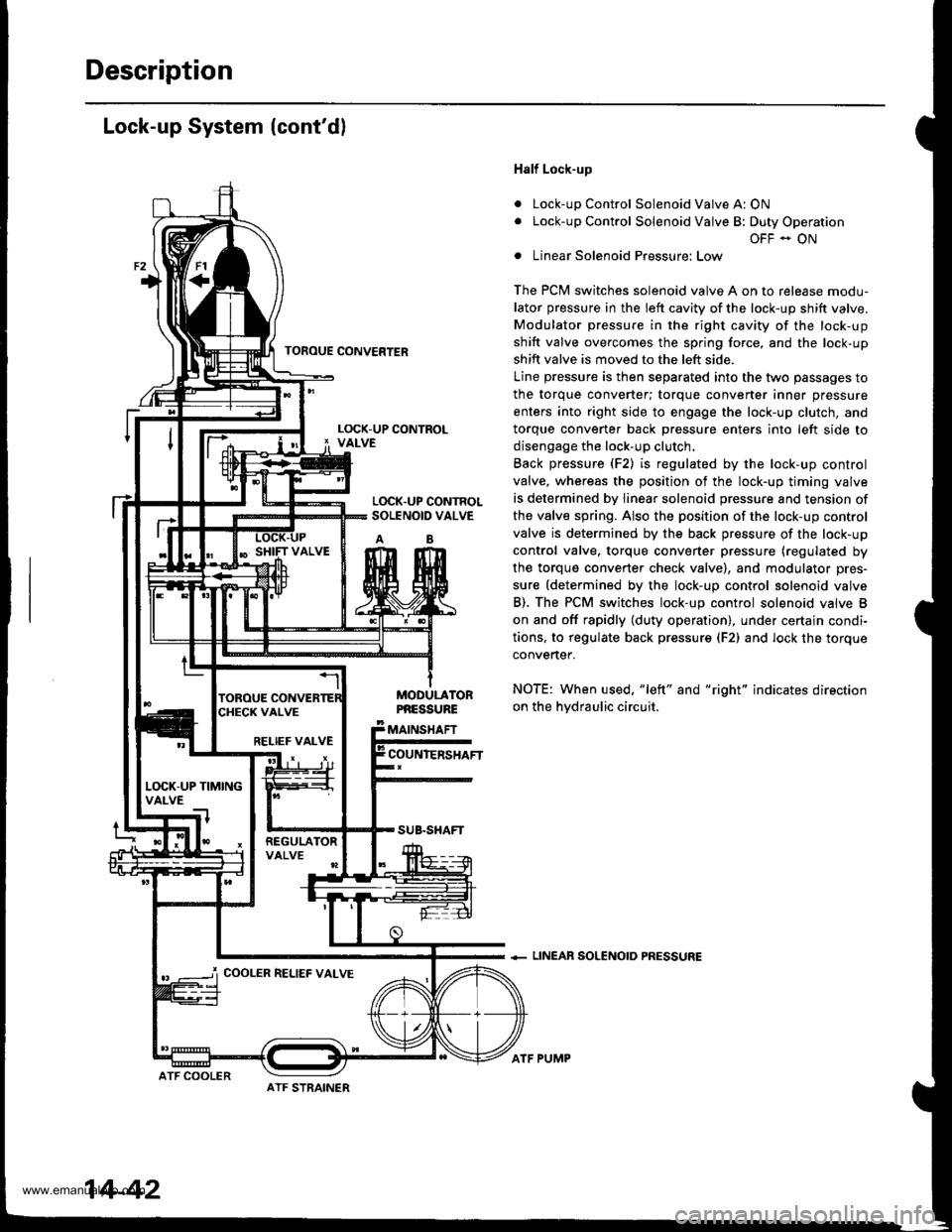
Half Lock-up
Lock-up Control Solenoid Valve A: ON
Lock-up Control Solenoid Valve B: Duty Operation
OFF - ON
Linear Solenoid Pressure: Low
The PCM switches solenoid valve A on to release modu-
lator pressure in the left cavity of the lock-up shift valve.
Modulator pressure in the right cavity of the lock-up
shift valve overcomes the spring force, and the lock-up
shift valve is moved to the left side.
Line pressure is then separated into the two passages to
the torque converter; torque converter inner pressure
enters into right side to engage the lock-up clutch, and
torque convener back Dressure enters into left side to
disengage the lock-up clutch.
Back pressure (F2) is regulated by the lock-up control
valve, whereas the position of the lock-up timing valve
is determined by linear solenoid pressure and tension of
the valve spring. Also the position of the lock-up control
valve is determined by the back pressure of the lock-up
control valve. torque converter pressure (regulated by
the torque converter check valve), and modulator pres-
sure (determined by the lock-up control solenoid valve
B). The PCM switches lock-up control solenoid valve B
on and off rapidly (duty operation), under certajn condi-
tions, to regulate back pressur€ (F2) and lock the torque
convertef.
NOTE: When used, "left" and "right" indicates direction
on the hvdraulic circuit.
+ LINEAR SOLENOID PRESSURE
TOFOUE CONVERTER
L(rcK.UP CONTROLSOLENOID VALVE
AB
MODULATORPNESSURE
MAINSHAFT
COUNIERSHAFTRELIEF VALVE
L(rcK-UP TIMINGVALVE
COOLER RELIEF VALVE
ATF STRAINER
14-42
ATF COOLER
ATF PUMP
www.emanualpro.com
Page 559 of 1395

TOROUE CONVEFTER
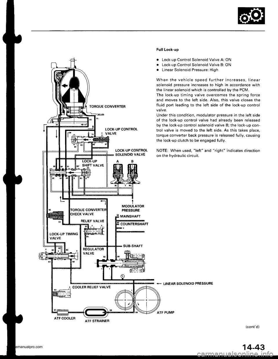
Full Lock-up
. Lock-up Control Solenoid Valve A: ON
. Lock-up Control Solenoid Valve B: ON
. Linear Solenoid Pressure: High
When the vehicle speed further increases, linear
solenoid pressure increases to high in accordance with
the linear solenoid which is controlled by the PCM.
The lock up timing valve overcomes the spring force
and moves to the left side. Also, this valve closes the
fluid port leading to the left side of the lock-up control
valve.
Under this condition, modulator pressure in the left side
of the lock-up control valve had already been released
by the lock-up control solenoid valve B; the lock-up con-
trol valve is moved to the left side. As this takes place,
torque converter back pressure is released fully, causing
the lock-up clutch to be engaged fully.
NOTE: When used. "left" and "right" indicates direction
on the hydraulic circuit.
+ LINEAR SOLENOIO PRESSURE
(cont'd)
LOCK-UP CONTROLSOLENOID VALVE
MODULATORPRESSURE
MAINSHAFT
COUNTERSHAFT
SUB-SHAFT
RELIEF VALVE
LOCK.UP TIMINGVALVE
COOLER BELIEF VALVE
ATF STRAINERATF COOLER
ATF PUMP
14-43
www.emanualpro.com
Page 560 of 1395
Description
Lock-up System (cont'dl
a
a
Decelelation Lock-up
Lock-up Control Solenoid Valve A: ON
Lock-up Control Solenoid Valve B; Duty Operation
OFF - ON
Linear Solenoid Pressure: Low
The PCM switches solenoid valve B on and off rapidly
under certain conditions. The slight lock-up and half
lock-up regions are maintained to lock the torque con-
vener propeny.
NOTE: When used, "left" and "right" indicates direction
on the hydraulic circuit.
+ LINEAR SOLENOID PRESSURE
TOROUE CONVERTER
tMOOULATORPRESSURE
MAINSHAFT
COUNTERSHAFT
SUB.SHAFT
ATF COOLER
RELIEF VALVE
LOCK.UP TIMINGVALVE
COOLER RELIEF VALVE
14-44
ATF STBAINER
ATF PUMP
www.emanualpro.com
Page 561 of 1395
Component Locations
ASSEMBLY
POWERTRAIN CONTROLMODULE {PCMI
COUNTERSHAFTSPEED SENSOR
AUTOMAIIC TRANSAXI.E(A/T} GEAR POSITIONswtTcH
\
CONTBOL UN]T
SHIFT CONTROLSOLEM)ID VALVEASSEMBLY
SPEED SCNSOR
14-45
www.emanualpro.com
Page 562 of 1395
PCM Circuit Diagram (A/T Control System)
'97 Model
UNDER.I]OOD FUSAFELAY BOXEATTEFY
_YEL_
T-l ,
TT-l
t_-:
G101
'Fr-r.04
P- r.-or..u L_a TMEALOC(BrK€ru -<< calTFoL
P_ *+rr
F- onmrxCFUISECONTFOLUNITf-"".>
| ["'"]
I l,[-l
III ;,
F_ pw
P_ eLu
F-- enN
UNDER DASN
M 25(7.54)
IGNITONSWITCH UNDEF OASNFUSAFELAYSOX
oowEa-qar. cor.lFo- MooLrE rpcMr F &*1 r*--'l_____O_=_ATP IO! ,ATP . ATD , A-P , A-P , A-PNP lrNo lR 101 103 12 ll
Ar'TGEAR POS]TIONswtcN
14-46
www.emanualpro.com
Page 564 of 1395

PGM Terminal Voltage/Measuring Conditions
A/T Control System -'97 Model
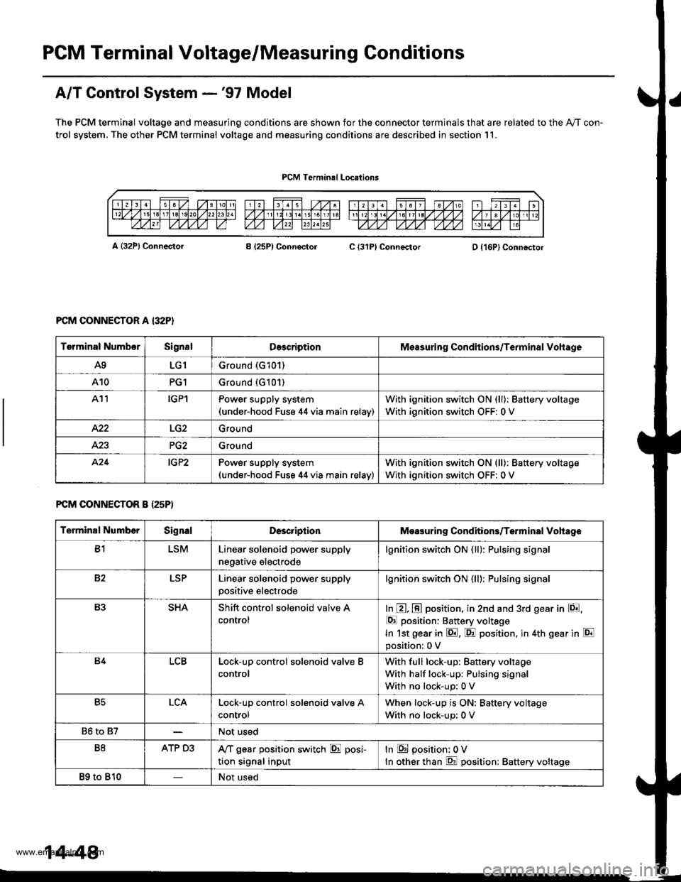
The PCM terminal voltage and measuring conditions are shown for the connector terminals that are related to the Ay'T con-
trol system. The other PCM terminal voltage and measuring conditions are described in section 11.
PCM Terminal Locations
A {32P} ConnectorB (25P1 ConnectolC {31PI ConnectorD {16P}Connector
PCM CONNECTOR A {32P}
FCM CONNECTOR B (25P)
Torminal NumbcrSignslDescriptionMeasuring Conditions/Terminal Vohage
A9LG1Ground (G101)
A10PG1Ground {G101)
At1IGPlPower supply system(under-hood Fuse 44 via main relav)
With ignition switch ON (ll): Battery voltage
With ignition switch OFF: 0 V
422Ground
Ground
424IG P2Power supply system(under-hood Fuse 44 via main relav)
With ignition switch ON (ll): Battery voltage
With ignition switch OFF: 0 V
Terminal NumberSignalDescriptionMeasuring Conditions/Terminal Vohage
B1LSMLinear solenoid power supply
negative electrode
lgnition switch ON (ll): Pulsing signa
82LSPLinear solenoid power supply
positive electrode
lgnition switch ON (lll: Pulsing signa
B3SHAShift control solenoid valve A
control
In @, @ position, in 2nd and 3rd gear in E,
E position: Battery voltage
In 1st gear in E. F! position, in 4th gear in E
position: 0 V
B4LCBLock-up control solenoid valve B
control
With full lock-up: Battery voltage
With half lock-up: Pulsing signal
With no lock-up: 0 V
B5LCALock-up control solenoid valve A
control
When lock-up is ON: Baftery voltage
With no lock-up: 0 V
86 to 87Not used
B8ATP D3,VT gear position switch E posi-
tion signal input
In E position: 0V
In other than E position: Battery voltage
89 to 810Not used
14-48
www.emanualpro.com
Page 565 of 1395

PCM CONNECTOR B (25P) lcont'd)
PCM CONNECTOR C {31PI
PCM CONNECTOR D II6PI
Terminal NumbelSignalDescriptionMeasuring Conditions/Terminal voltage
811SHBShift control solenoid valve B
control
In E, E position, in 1st and 2nd gear in -q,
Er position: Battery voltage
In B position, in 3rd gear in qd, q:l,in atn
gear in D. position: 0 V
812ILUlnterlock controlWhen ignition switch is ON (ll), brake pedal
deDressed and accelerator oedal released:0 V
B13D4 INDD4 Indicator light controlWhen ignition switch is first turned ON (ll): 6 V
or more for tlvo seconds
In lDll position: 6V or more
814NMSGMainshaft speed sensor ground
815NMMainshaft speed sensor signal
InpuI
Depending on engine speed: Pulsing signal
When engine is stopped: 0 V
816ATP RAy'T gear position switch Eposition signal input
In E position; OV
In other than E position: Battery voltage
817ATP 2Ay'T gear position switch E posi-
tion signal input
InEposition:0V
In other than E position: Battery voltage
B18ATP 1A/T gear position switch El posi-
tion signal input
InEposition:0V
In other than E position: Battery voltage
819 to 821Not used
B�22NCSGCountershaft speed sensor ground
NCCountershaft speed sensor signal
Inpur
Depending on vehicle speed: Pulsing signal
when vehicle is stooped: 0 V
824ATP D4A/T gear position switch iql posi-
tion signal input
In E position: 0V
In other than lgal position: Baftery voltage
825ATP NPAy'T gear position switch E and
N position signals input
In E and E positions: 0V
In otherthan @ and ffi positions:5 V
Terminal NumberSignalDescriptionMeasuring Conditions/Terminal Voltage
SCSService check signalWith ignition switch ON (ll) and service check
connector open: 5 V
With ignition switch ON (ll) and service check
connector connected with special tool: 0 V
c10VBUBack-up power system(under-hood Fuse 47)
Always battery voltage
Terminal NumberSignalDescriptionMeasuring Conditions/Terminal Voltage
STOP SWBrake switch signal inputBrake pedal pressedr Battery voltage
Brake pedal released: 0 V
14-49
www.emanualpro.com
Page 568 of 1395
PCM Circuit Diagram (A/T Control System)
'99 - 00 Models
IJNOER'HOOD FUSE/FELAY EoXEATTERY
IJNOER DASIIFUS'/FELAYBOX
-]-
T8LKryEL
l.
]T
IBLX,'YEL
D9 100 | 0r4 | Drt I Btg
GAUGEASSEMELYFffi[t**
f L'om {+ sr&BrLr --1 l-
LTGRN
BLKtsLU
FED
YEL
8LU
LI BLU
F-lwr-i
|--FED----.1
|-BFN--
f- Lr sLrJ -l
,I,-r
G4o1
d
G401
AIP,O,0,ATP,ArPlO/D04 t5w t2 tr tN0
){:-\
!r'TGEAF POS]IION
14-52
www.emanualpro.com