Page 1080 of 1395
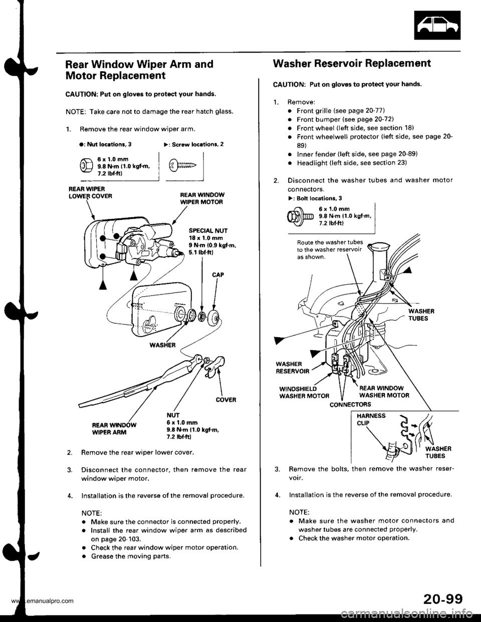
Rear Window Wiper Arm and
Motor Replacement
CAUTION: Put on gloves to protect your hands.
NOTE; Take care not to damage the rear hatch glass.
1. Remove the rear window wiper arm.
a: Nut loc.tion!, 3>: Scaow locationa, 2
REAR WINDOWWIPER MOIOR
REAR WIPERCOVER
REARWIPER ARM
6x1.0mm9.8 N.m 11.0 kgt'm,7.2 tbf.ftl
SPECIAL NUT18 x 1.0 mm9 N.m 10.9 kgt m,5. r tbt.ftl
NUT6x 1.0mm9.8 N.m {1.0 kgt.m,?.2 tbfftl
Remove the rear wiper lower cover.
Disconnect the connector, then remove the rear
window wiper motor.
Installation is the reverse of the removal procedure.
NOTE:
. Make sure the connector is connected properly.
. Install the rea. window wiper arm as described
on page 20-103.
. Check the rear window wiper motor operation.
. Grease the moving parts.
@rrc
Washer Reservoir Replacement
GAUTION: Put on gloves to protect your hands.
1. Remove:
. Front grille (see page 20-771
. Front bumper (see page 20-721
. Front wheel {left side, see section 18)
. Front wheelwell protector (left side, see page 20-
89)
. Inner fender (left side, see page 20-89)
. Headlight (left side, see section 23)
2. Disconnect the washer tubes and washer motor
connectors.
>: Bolt locations, 3
6x1.0mm9,8 N.m 11.0 kgt.m,7.2 tbt.ftl
Route the washer tubesto the washer teservoir
WASHERRESERVOIR
WINOSHIELOWASHER MOTON
CONNECTORS
3. Remove the bolts, then remove the washer reser-
votr,
4. Installation is the reverse of the removal procedure.
NOTE:
a Make sure the washer motor connectors and
washer tubes are connected properly.
. Check the washer motor operation.
HARNESS / tcLrP C-(fu
- S(ilq
s{J
l' wrsHER
20-99
www.emanualpro.com
Page 1083 of 1395
Wiper/Washer
Rear Window Washer Tube Replacement (cont'dl
REAR WINDOWWASHER NOZZLE GSOMMET
\
t
i;r."'..--a
B
REAR WINDOWWASHER TUBE
Route the washer tubeundor the wire harness,
Installation is the reverse of the removal Drocedure.
NOTE;
. Take care not to pinch the washer tubes.. lf necessary, replace any damaged clips.. After installing, adjust the aim of the washer nozzle (see page 20-103).
20-102
www.emanualpro.com
Page 1090 of 1395
a
Heater and Air Conditioning
Heater ...........21
NOTE: Section 21 ("Heater") is included in section 22.
Air Conditioning ......'..'.. '.'22'1
SUPPLEMENTAL RESTRAINT SYSTEM (SRS}
This model has an SRS which includes a driver's airbag in the steering wheel hub, a passenger's airbag in the dashboard
above the glove box ('97,00 models). and seat belt tensioners in the seat belt retractors ('98 - 00 models). Information
necessary to safely service the SRS is included in this Service Manual. ltems marked with an asterisk (*) on the contents
page include. or are located near, SRS components. Servicing, disassembling or replacing these items will require special
precautions and tools, and should only be done by an authorized Honda dealer.
@. To avoid rendering the SRS inoperative, which could lead to personal iniury or death in the event of 8 severe frontal
collision, all SRS service work must be performed by an authotized Honda dealer.
lmproper service procedures, including incorrect removal and installation of the SRS, could lead to personal iniury
caused by unintentional deployment of the airbags ('97 - 00 models), and seat belt tensioners 138 - 00 models).
Do not bump the SRS unit. Otherwise, the system may fail in case of a collision, or the airbags may deploy when the
ignition switch is ON {lll.
SRS eleqtrical wiring harnesses are identified by yellow color coding. Related components are located in the steering
column, front console, dashboard, dashboard lower panel, and in the dashboard above the glove box. Do not use elec-
tricaltest equipment on thes€ cilcuils.
www.emanualpro.com
Page 1150 of 1395
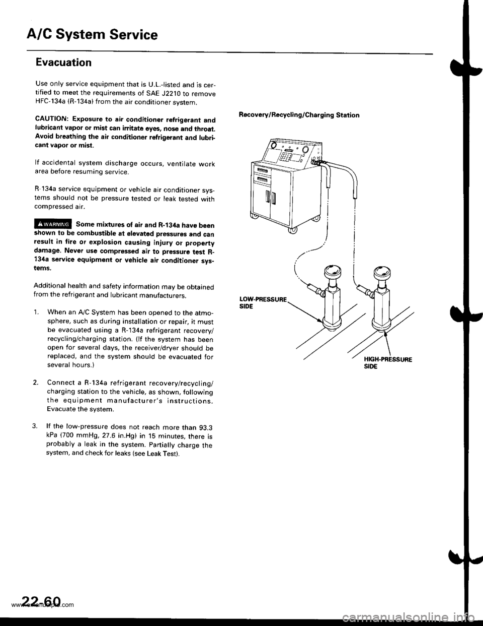
A/C System Service
Evacuation
Use only service equipment that is U.L.-listed and is cer-tified to meet the requirements of SAE J2210 to removeHFC-134a {R-134a)from the air conditioner system.
CAUTION: Exposure to air conditioner refrigerant andlubricant vapor or mist can irrhate eyes, noso and throat.Avoid breathing the air condhioner retrigerant and lubri-cant vapor or mist.
lf accidental system discharge occu.s. ventilate workarea before resuming service.
R 134a service equipment or vehicle air conditioner sys-tems should not be pressure tested or leak tested withcompressed arr.
!@ some mixtures of air and R-134a hsvo beenshown to be combustible at elevated pressures and canresult in tire or explosion causing iniury ot property
damage. Never use compressed air to pressure test R-134a service equipment or vehicle air conditioner svs-tems.
Additional health and safety information may be obtainedfrom the refrigerant and lubricant manufacturers.
1, When an A,/C System has been opened to the atmo-
sphere, such as during installation or repair, it must
be evacuated using a R-l34a refrigerant recovery/
recycling/charging station. {lf the system has beenopen for several days, the receiver/dryer should bereplaced, and the system should be evacuated forseveral hours.)
Connect a R-134a refrigerant recovery/recyclin g/
charging station to the vehicle, as shown, following
the equipment manufacturer's instructions.
Evacuate the system,
lf the low-pressure does not reach more than 93.3kPa (700 mmHg,27.6 in.Hg) in 15 minutes, there isprobably a leak in the system. partially charge thesystem, and check for leaks (see Leak Test).
Recovery/Recycling/Charging Station
22-60
www.emanualpro.com
Page 1209 of 1395
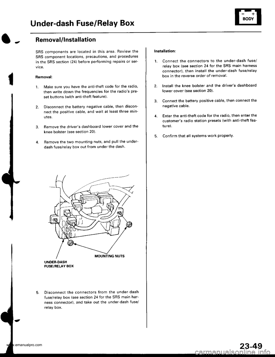
Under-dash Fuse/Relay Box
I
Removal/lnstallation
SRS components are located in this area. Review the
SRS component locations, precautions, and procedures
in the SRS section (241 before performing repairs or ser-
vice.
Removal:
1. Make sure you have the anti-theft code for the radio,
then write down the frequencies for the radio's pre-
set buttons (with anti-theft feature).
2. Disconnect the battery negative cable, then discon-
nect the positive cable, and wait at least three min-
utes.
3. Remove the driver's dashboard lower cover and the
knee bolster (see section 20).
4. Remove the two mounting nuts, and pull the under-
dash fuse/relay box out from under the dash
Disconnect the connectors from the under-dash
fuse/relay box (see section 24 for the SRS main har-
ness connector), and take out the under-dash fuse/
relay oox.
Installation:
1. Connect the connectors to the under-dash fuse/
relay box (see section 24 for the SRS main harness
connector), then install the under-dash lusehelay
box in the reverse order of removal.
2. lnstall the knee bolster and the driver's dashboard
lower cover (see section 20).
3. Connect the battery positive cable, then connect the
negative cable.
4. Enter the anti-theft code for the radio, then enter the
customer's radio station presets (with anti-thett fea-
ture).
5. Confirm that all systems work properly
23-49
www.emanualpro.com
Page 1304 of 1395
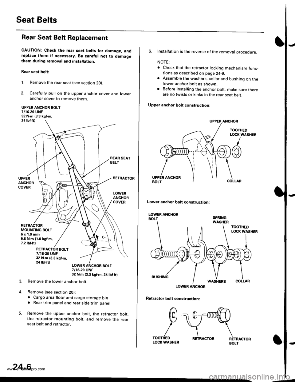
Seat Belts
Rear Seat Belt Replacement
CAUTION: Check the rear s€at belts for damage, andreplace lhem if necessa.y. Be caretul not to damagethem during temoval and installation.
Rear seat belt:
1, Remove the rear seat {see section 20}.
2. Carefully pull on the upper anchor cover and loweranchor cover to remove them.
UPPER ANCHOR BOLT7/16-20 UNF32 N.m 13.3 kg{.m,24 tbt.ft)
REAR SEATBELT
RETRACTOBMOUNTING BOLT6x1.0mm9.8 N.m (1.0 kgt.m.7.2 rbf.ftl
UPPERANCHORCOVER
RETRACTOR
LOWERANCHORCOVER
RETRACIOR EOLT7/16-20 UNF32 N.m {3,3 kgf.m,24 rbr.ft)
3.
4.
LOWER ANCHOF BOLT7/1S20 UNF32 N.m 13.3 kgl.m, 2/r lbf.ftl
Remove the lower anchor bolt.
Remove (see section 20):. Cargo area floor and cargo storage bin. Rear trim panel and rear side trim panel
Remove the upper anchor bolt, the retractor bolt.the retractor mounting bolt, and remove the rearseat belt and retractor.
24-6
,--
6. Installation is the reverse of the removal procedure.
NOTE:
. Check that the retractor locking mechanism func-tions as described on page 24-9.. Assemble the washers, collar and bushing on thelower anchor bolt as shown.. Before installing the anchor bolt, make sure thereare no twists or kinks in the rear seat belt.
Upper anchot bolt construction:
UPPER ANCHOR
TOOTHEOLOCK WASHER
/
A t
ANCHORCOLLAF
Lowel anchor bolt construqtion:
LOWER ANCHORBOLTSPRINGWASHEB
TOOTHEDLOCI( WASHER
BUSHINGWASHERSCOLLAR
LOWER ANCHOR
Rgtractor boll construction:
RETMCTORBOLT
/ r>--->.
f/F\-. (t--nnnllH \
P \v*\
/\\T(X)THEDLOCK WASHERRETRACTOR
www.emanualpro.com
Page 1306 of 1395
Seat Belts
Rear Seat Belt Replacement (cont'dl
5. Installation is the reverse of the removal Drocedure.
NOTE: Make sure there are no twists or kinks in thecenter belt tongue and seat belt buckle.
Cenler anchor bolt construction:
€
\TOOTHEDLOCK WASHER
ANCHOR
24-8
,-4
www.emanualpro.com
Page 1308 of 1395
Seat Belts
Chifd Seat Tether Anchor Installation -,97 - 99 Models
Canada model:
Attachment points are provided for a rear sear mountedchild restraint system which uses a top tether. The attach_ment points are located on both rear corners of the head_liner, just behind the rear seat-back. When using a childseat with a top tether, install the child seat tether anchorsecurelv.
NOTE: To install a child seat on the rear seat, select theattachment point you want to use, and remove the plugcover from the attachment point of the headliner. Installthe child seat tether anchor securely.
ATTACHMENTPOINTS
PLUG COVERS
CHILO SEATTETHERANCHORTOOTHED WASHER
24-10
-4
NOTE:
. Do not remove the toothed washer from the child seattether anchor. Use the seat anchor with the toothedwasher attached to it.. When installing a child seat on the rear seat, followthe instructions of the manufacturer of the child seat.. Additional anchors are available.
-
www.emanualpro.com