Page 119 of 1395

Valve Seals
12.
Replacement (cylinder head removal not requiredl (cont'dl
Using an upward motion on the lever arm, compress
the valve spring and remove the keepers from the
valve stem. Slowly release pressure on the spring.
Repeat step 11 for the other valve in that cylinder.
Remove the valve seals (see page 6-24).
Installthe valve seals (see page 6-29).
lnstall the springs, the retainers and the keepers in
reverse order of removal.
'17. Repeat steps 9 to 16 for the other three cylinders.
Exhaust valve Seals
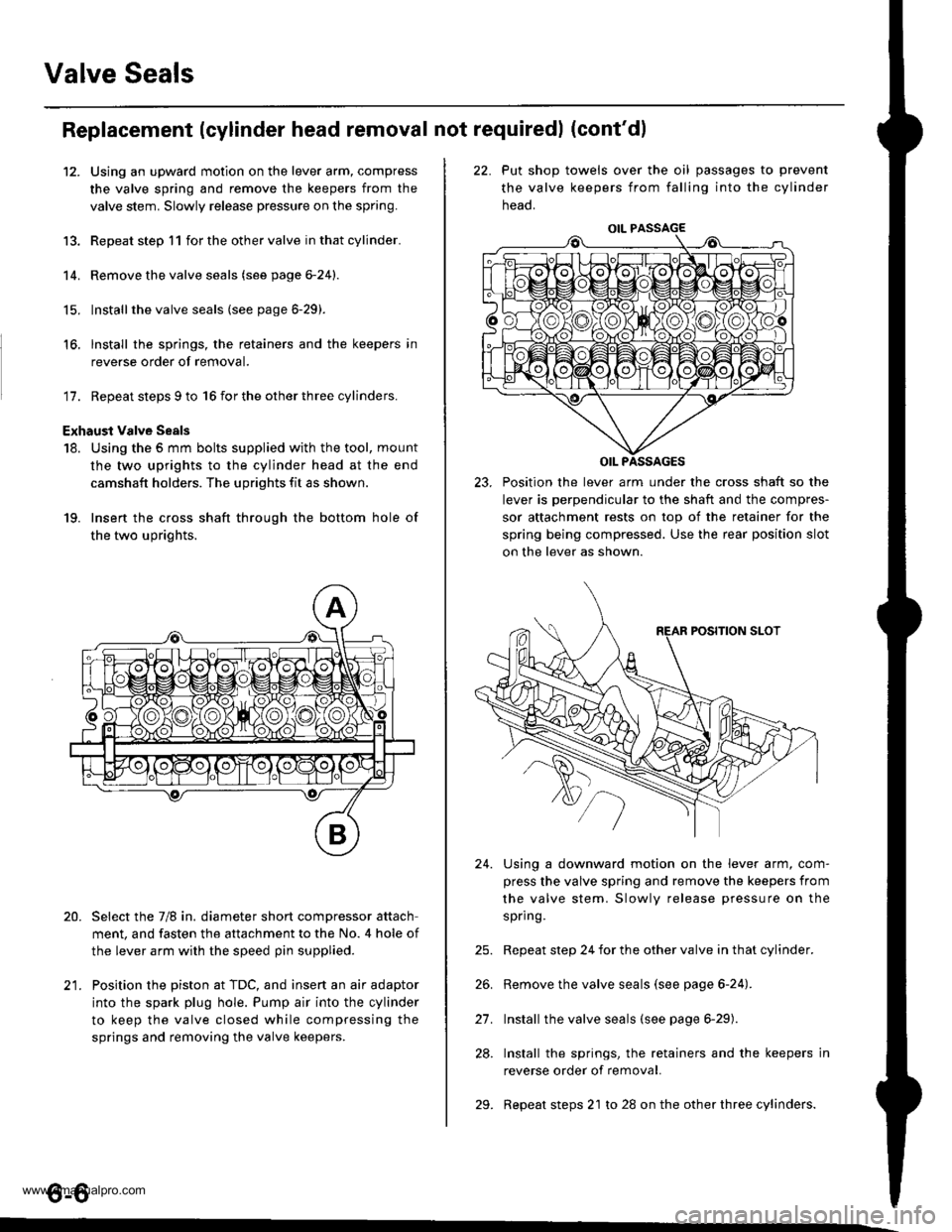
18. Using the 5 mm bolts supplied with the tool, mount
the two uprights to the cylinder head at the end
camshaft holders. The uprights fit as shown.
19. Insert the cross shaft through the bottom hole of
the two uprights.
Select the 7/8 in. diameter short compressor attach
ment, and fasten the attachment to the No. 4 hole of
the lever arm with the speed pin supplied.
Position the piston at TDC, and insert an air adaptor
into the spark plug hole. Pump air into the cylinder
to keep the valve closed while compressing the
springs and removing the valve keepers.
13.
14.
15.
16.
20.
t1
22. Put shop towels over the oil passages to prevent
the valve keepers from falling into the cylinder
neao.
23. Position the lever arm under the cross shaft so the
lever is perpendicular to the shaft and the compres-
sor attachment rests on top of the retainer for the
spring being compressed. Use the rear position slot
on the lever as shown.
Using a downward motion on the lever arm, com-
press the valve spring and remove the keepers from
the valve stem. Slowly release pressure on the
spring.
Repeat step 24 for the other valve in that cylinder.
Remove the valve seals (see page 6-24).
Install the valve seals (see page 6-29).
Install the springs, the retainers and the keepers in
reverse order of removal.
Repeat steps 21 to 28 on the other three cylinders.
24.
21.
28.
29.
o-o
www.emanualpro.com
Page 124 of 1395

8. Remove the cylinder head cover.
NOTE: Refer to page 6-32 when installing the cylin-
der head cover.
Remove the crankshaft pulley (see page 6-7).
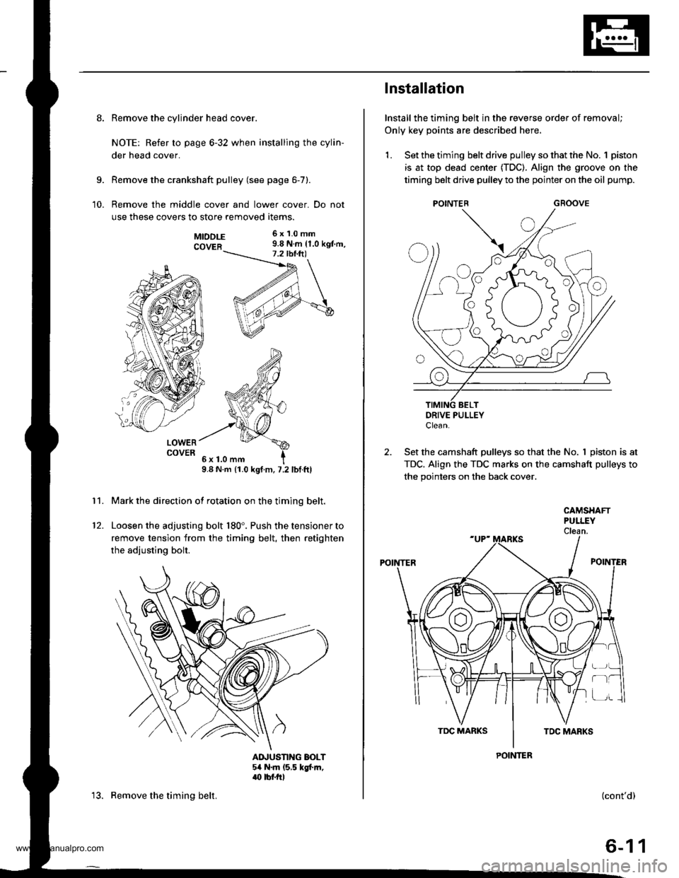
Remove the middle cover and lower cover. Do not
use these covers to store removed items.
9.
10.
11.
MTDDLE 6x1.0mm
COVER 9.8 N.m {1.0 kgt m,
LOWERCOVER
9.8 N.m (1.0 kgt.m, 7.2 lbf.ftl
Mark the direction of rotation on the timing belt.
Loosen the adjusting bolt 180'. Push the tensioner to
remove tension from the timing belt, then retighten
the adiusting bolt.
AINUSTING BOLT54 N.m (5,5 kgt m,.(} tbf.rrl
12.
13. Remove the timing belt.
Installation
Install the timing belt in the reverse order of removal;
Only key points are described here,
1. Set the timing belt drive pulley so that the No. 1 piston
is at top dead center (TDC). Align the groove on the
timing belt drive pulley to the pointer on the oil pump.
GROOVE
DRIVE PULLEYClean.
2. Set the camshaft pulleys so that the No. I piston is at
TDC. Align the TDC marks on the camshaft pulleys to
the pointers on the back cover.
POINTER
CAMSHAFTPULLEYClean.
POINTER
r-t
(cont'd)
6-11
www.emanualpro.com
Page 156 of 1395

Pistons and Crankshaft
Removal (cont'dl
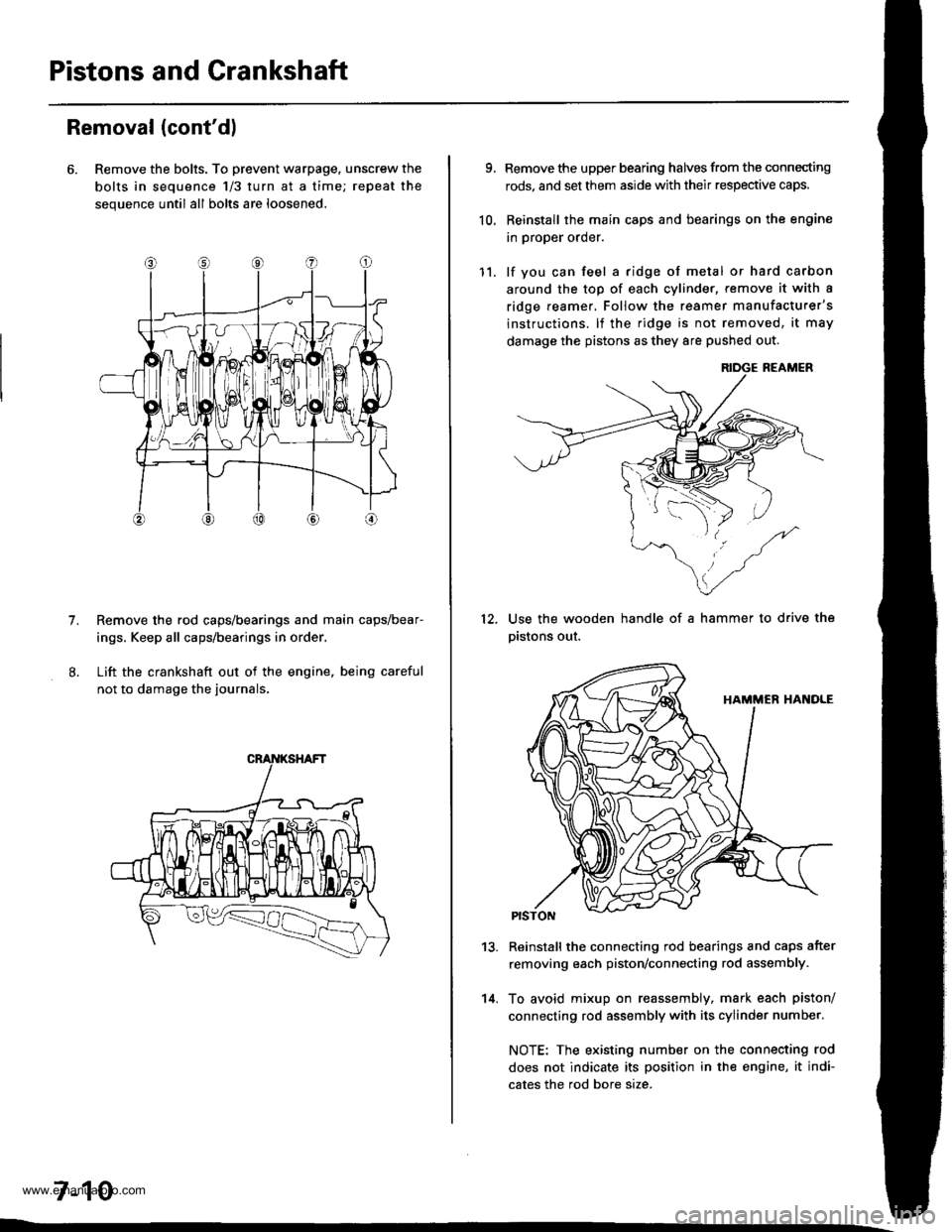
6. Remove the bolts. To prevent warpage, unscrew the
bolts in sequence 1/3 turn at a time; repeat the
sequence until all bolts are loosened.
Remove the rod caps/bearings and main caps/bear-
ings, Keep all caps/bearings in order
Lift the crankshaft out of the engine. being careful
not to damage the journals.
7.
7-10
9.
10.
Remove the upper bearing halves from the connecting
rods, and set them aside with their respective caps.
Reinstall the main caps and bearings on the engine
in proper order.
lf you can feel a ridge of metal or hard carbon
around the top of each cvlinder, remove it with a
ridge reamer. Follow the reamer manufacturer's
instructions. lf the ridge is not removed, it may
damage the pistons as they 8re pushed out.
12.
11.
14.
Use the wooden handle of a hammer to drive the
pistons out.
13.Reinstall the connecting rod bearings and caps after
removing each piston/connecting rod assembly.
To avoid mixup on reassembly, mark each piston/
connecting rod assembly with its cylinder number.
NOTE: The existing number on the connecting rod
does not indicate its position in the engine, it indi-
cates the rod bore size.
www.emanualpro.com