Page 1261 of 1395
E
t J Circuit Diagram
UNDER.HOOO FUSE/FELAY BOXUNOEB,DASHFIJSE/RELAY BOX
l-^*"-l
T'5 1-T
I
I
I
I
I
IYEURED
No.30 (7.5A)FUSE
WHT,tsLK
BRN/BLK
s tr4 | 1 l7l
a,-,
1s l16l| 7[61
GHY,ryVHT
IGNITION SWITCH
AUOIO UNIT
oo oo
LEFT REARSPEAKERRIGHT BEARSPEAKERLEFI FRONTDOOF SPEAKERRIGHT FBONTDOOB SPEAKER
23-101
www.emanualpro.com
Page 1267 of 1395
Power Mirrors
Circuit Diagram
IGNITION SWITCH
lBAI \-€l ^rc2l.Y
YEL
I
-t----t
I lu.'x I
IBLKIryEL
@"*'
POWEN MIRRON SWTCH
UNDER,DASHFUSE/RELAYB0x
GRN vHT +l
35
BLK
-:
G551
l,-
[ ] : '9&00 rnodels
UNDER.HOOD FUSURELAY BOX
N0.41 (100A) N0.42 (40A)WHT/8LK +WHT
YEUREDBLUMHT
-
23-107
www.emanualpro.com
Page 1268 of 1395

Power Mirrors
Function Test
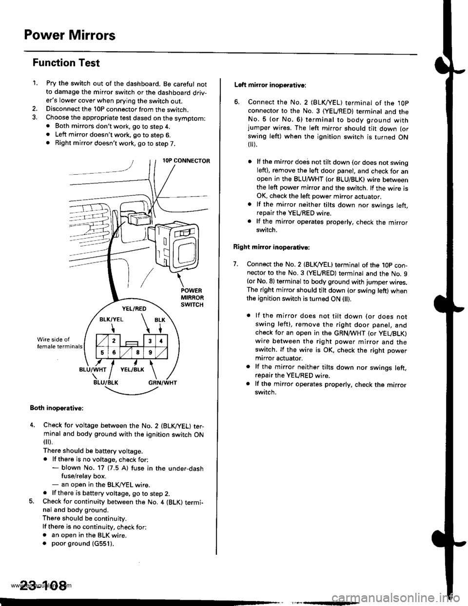
1.Pry the switch out of the dashboard. Be careful notto damage the mirror switch or the dashboard driv-er's lower cover when prying the switch out.Disconnect the 10P connector from the switch.Choose the appropriate test dased on the symptom:. Both mirrors don't work, go to step 4.. Left mirror doesn't work, go to step 6.. Right mirror doesn't work, go to step 7.
Both inoperative:
4. Check for voltage between the No. 2 (BLVYEL) ter-minal and body ground with the ignition switch ON
fl r).
There should be baftery voltage,. lf there is no voltage, check for:- blown No. 17 (7.5 A) fuse in the under-dashfuse/relay box.- an open in the BLK,/YEL wire.. lf there is battery voltage, go to step 2.5. Check for continuity between the No. 4 {BLK) termi-nal and body ground.
There should be continuity.
lf there is no continuity, check for;. an open in the BLK wire.. poor ground (c551).
,
-.t-..------'-
23-108
Left mirror inoperative:
6. Connect the No. 2 {BLKI/EL) terminal of the ,l0p
connector to the No. 3 (YEUREDI terminal and theNo.5 (or No.6) terminal to body ground withjumper wires. The left mirror should tilt down (or
swing left) when the ignition switch is turned ON t).
lf the mirror doei not tilt down (or does not swingleft), remove the left door panel, and check for anopen in the BLUMHT (or BLU/BLK) wire betweenthe left power mirror and the switch. lf the wire isOK, check the left power mirror actuator,
lf the mirror neither tilts down nor swings left,repair the YEURED wire.
lf the mirror operates properly, check the mirrorswitch.
Right mirror inoperaiiva:
7. Connect the No. 2 {BLVYEL) terminat of the 1Op con-nector to the No. 3 (YEURED) terminal and the No. 9(or No. 8) terminal to body ground with jumper wires.The right mirror should tilt down (or swing left) whenthe ignition switch is turned ON l).
. lf the mirror does not tilt down (or does notswing left), remove the right door panel, andcheck for an open in the GRN,4TVHT (or yEUBLK)
wire between the right power mirror and theswitch. lf the wire is OK, check the right power
mtrror actuator.
. lf the mirror neither tilts down nor swings left.repair the YEURED wire.. lf the mirror operates properly, check the mirrorswitch.
www.emanualpro.com
Page 1270 of 1395
Rear Window Defogger
Gomponent Location Index
FUSE/RELAY BOX
REAB WINDOW DEFOGGER SWTTCHInput Test, p89e 23-113
REAR WINDOW DEFOGGERFunction Test. page 23-112DetoggerWre Repair, page 23-112
rr^ja} aia al Irl
!
23-110
www.emanualpro.com
Page 1273 of 1395
Switch Input Test
NOTE: Before testing, check for blown No. 17 (7.5 A)
fuse in the under-dash fuse/relay box.
1. Remove the center panel {see section 20).
REAR WINOOW DEFOGGER SWITCHlin the heater control oanel)CENTER PANEL
Check for voltage between the 84 and 87 terminals
in each switch position when battery power is con-
nected to the B l terminal.
OFFless than 0.4 V
ONbaftery voltage
Ol-
I
-
23-113
www.emanualpro.com
Page 1274 of 1395
Wipers/Washers
Component Location Index
SRS components are located in this area. Review the SRs component locations, precautions, and procedures in the s6ssection (24) before performing repairs or service.
REAB WINDOW WIPER MOTOBT€st, page 23-120WPSR/WASHER SWITCHTest. page 23- l't9
REAR WINDOW WIPERCONTROL UNlT 137 mod.llInput test. page 23-118
WINDSHIELD WIPER MOTORTost, page 23-119
UNDER.DASH FUSE/RELA
INTERMITTENT W|PEN RELAYCIBCUIT, REAR WINDOW INTERMTNENTwlPER RELAY CIBCUIT l'98 - 0O mod.t.lBOX (ln the integrated control unit)Input test, page 23-68
23-114
-
n
tff
www.emanualpro.com
Page 1275 of 1395
UNDEB,DASHFUSENELAY BOXIGNITON SWITCH
l-Circuit Diagram {Windshieldl
@*"
BLUiBLK
YEUBLU
WHTiBLK
l-
BLK
I
I
I
I_L
G401G402
23-115
8LK
G401G402
BLK
G401G402
UNDEB.HOOD FUSE/NELAY BOX
N0.41 (1004) N0.42 {40A)
INTEGEATEDCONTFOLUNIT
/ Has bui[-in \I inlermiltenl I wiper relay /
www.emanualpro.com
Page 1276 of 1395
Wipers/Washers
Circuit Diagram (Rear Window) -'97 Model
UNDER.HOOD FUSE/RELAY BOX
@**'
N0.41 (100A) N0.42 (40A)WHT/BLK +WHT
I
G611G631
t'8LK
I
G202
,7!is--- ---- ----
JiJ frT
BLK
d-l
G401G4A2
23-116
www.emanualpro.com