1997 HONDA CIVIC left kick panel
[x] Cancel search: left kick panelPage 350 of 2189
Troubleshooting
Troubleshooting Procedures
How To Begin Troubleshooting
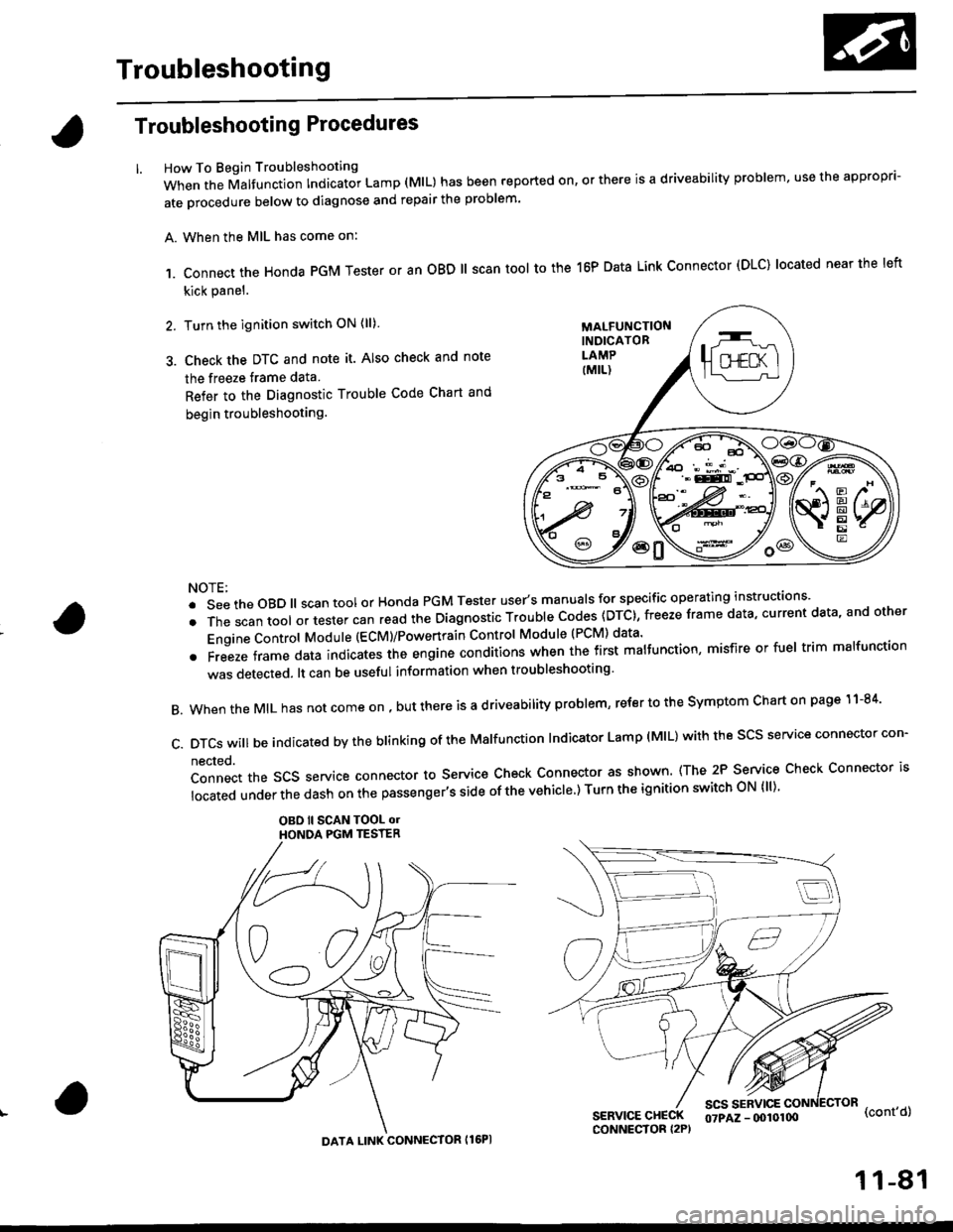
When the Malfunction Indicator Lamp (MlL) has been reported on, or there is a driveability problem, use the appropr'-
ate orocedure below to diagnose and repair the problem'
A. When the MIL has come on:
,1. connect the Honda PGM Tester or an oBD ll scan tool to the 16P Data Link connector (DLC) located near the left
kick panel.
2. Turn the ignition switch ON (ll)
3. Check the DTC and note it. Also check and note
the freeze trame data
Refer to the Diagnostic Trouble Code Chart and
begin troubleshooting.
NOTE:
.SeetheoBD||scantoolorHondaPGMTesteruser,smanua|sforspecificoperatinginstructions..
.Thescantoo|oltestercanreadtheDiagnosticTroub|ecodes(DTc},freezeframedata,currentdata,andother
Engine Control Module (ECM)/Powertrain Control Module (PCM) data'
oFreezeframedataindicatestheengineconditionswhenthefirstma|function,misfireorfue|trimma|function
was detected. lt can be useful information when troubleshooting'
B. When the MIL has not come on , out there is a d riveability problem, refer to the Symptom Chart on page 1 1-84'
c.DTcswi|lbeindicatedbytheb|inkingoftheMa|function|ndicatorLamp(M|L)withthescsserviceconnectorcon.
nected.
Connect the SCS service connector to Service Check Connector as shown (The 2P Service Check Connector is
|ocatedunderthedashonthepassenger,ssideofthevehic|e')TurntheignitionswitchoN{||)'
OBO ll SCAN TOOL olHONOA PGM TESTER
SERVICE CHECKCONNECTOR I2P)
scs sERvlcE(cont'd)
MALFUNCTIONINDICATORLAMP
DATA LINK CONNECTOR Il6PI
07PAZ - (x)l0100
11-81
Page 911 of 2189
Troubleshooting Procedures
l. How To Begin Troubleshooting
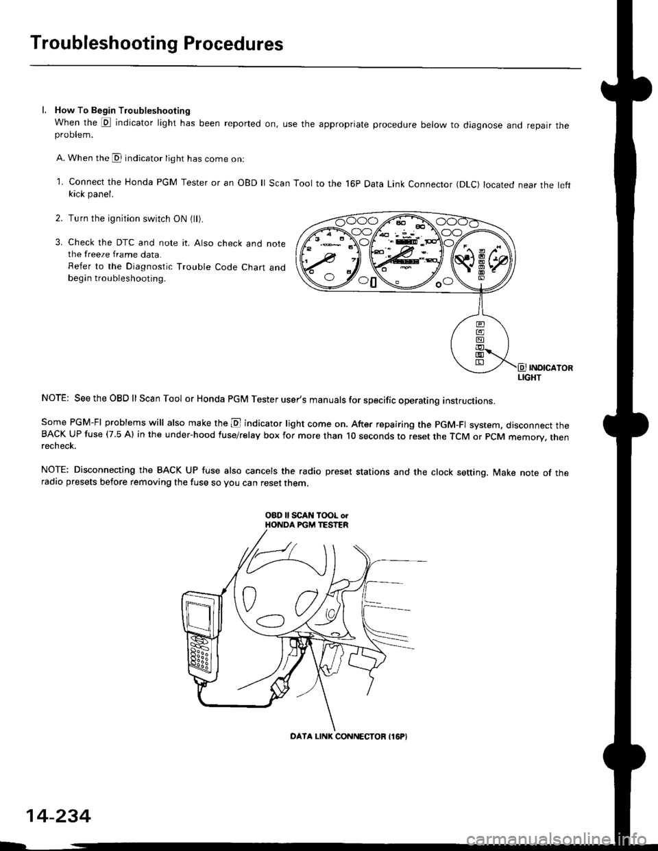
When the E indicator light has been reported on, use the appropriate procedure below to diagnose and repatr theproDlem.
A. When the @ indicator light has come on:
l connect the Honda PGM Tester or an oBD ll Scan Tool to the 16P Data Link Connector (DLc) located near the leftkick panel.
Turn the ignition switch ON (ll).
Check the DTC and note it. Also check and notethe freeze frame data.
Refer to the Diagnostic Trouble Code Chart andbegin troubleshooting.
INOICATORLIGHT
NOTE: SeetheOBDll Scan Tool or Honda PGM Tester user's manuals for specific operating instructions.
Some PGM-FI problems will also make the E indicator light come on. After repairing the pGM-Fl system, disconnect theBACK UP fuse (7.5 Al in the under-hood fuse/relay box for more than l0 seconds to reset the TCM or PCM memory, rnenrecheck.
NOTE: Disconnecting the BACK UP fuse also cancels the radio preset stations and the clock setting. Make note of theradio presets before removing the fuse so you can reset them,
2.
3.
o0\e--loo
OATA LINK CONNECTOB I16P}
14-234
Page 1290 of 2189
lnterior Trim
Replacement (cont'dl
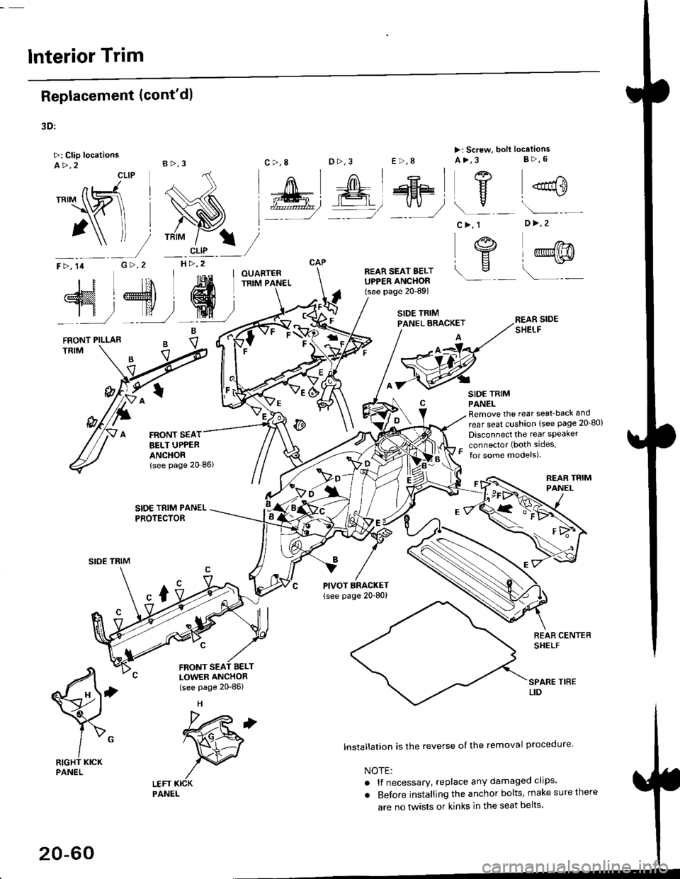
3D:
>: Clip locationsA>,2CLIP
N;
nt-.l I'"'\R
I
")!
F >, lil
TRIM
B>,3
G >,2H>,2
t
FRONT SEATBELT UPPEBANCHORlsee page 20 86)
SIDE TRIM PANELPROTECTOR
LEFT KICKPANEL
c >,8o>,3
PIVOT BRACKET
{see page 20-80)
lnstallation is the reverse of the removal procedure
NOTE:
. lf necessary, replace any damaged clips'
. Before installing the anchor bolts, make sure there
are no tlvists or kinks in the seat belts'
E >,8
>: Screw, bolt locationsA>,3 8>,6
^l l-lEF\
#, A@ Y
*"0
c>, 1
I "4"
\s
o >,2
l@@
\---
s,4, ffi;T
FRONT PILLARB
eV
REAR SIDESHELF
SIDE TRIMPANELRemove the rear seat-back and
rear seat cushion (see Page 20_80)
Disconnect the rear speaker
connector (both sides,
for some models).
REAR TRIMPANEL
q
RIGHT KICKPANEL
"x-
20-60
Page 1291 of 2189
Il
2Di
>: Clip locationsa>,28>,3
CLIP
G>,4H >,2
D >,3>i Screw location3.4
REAR SHELF
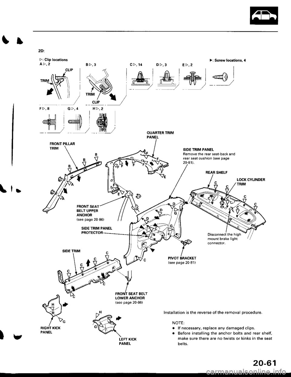
SIOE TRIM PANELRemove the rear seat-back andrear seat cushaon (see page20-a1l.
,
Disconnect the highmount brake light
SEAT BELT
€'
/>"RIGHT KICKPANEL
)
TRIM
nJ'.'rI\ZI
1\f-
F>,8
N 4'dr
SIDE TRIM
LOWER ANCHOR(see page 20-86)
c>, 14E>,2
Installation is the reverse of the removal procedure.
NOTE:
. lf necessary, replace any damaged clips.
. Before installing the anchor bolts and rear shelf,
make sure there are no twists or kinks in the seat
belts.
FRONT PILLAR
FRONT SEATBELT UPPERANCHOR
v
.h,'t6d
\
LEFT KICKPANEL
20-61
Page 1296 of 2189
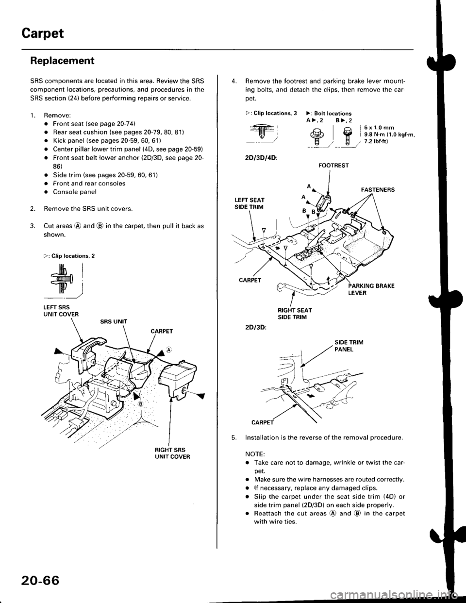
Carpet
Replacement
SRS components are located in this area. Review the SRS
component locations, precautions, and procedures in the
SRS section {24} before performing repairs or service.
1. Remove:
. Front seat (see page 2O-7 4l
. Rear seat cushion (see pages 20 79, 80, 81)
o Kick panel (see pages 20-59, 60, 61)
o Center pillar lowertrim panel i4D, see page 20-59)
. Front seat belt iower anchor (2Dl3D, see page 20-
86)
. Side trim (see pages 20-59, 60,61)
o Front and rear consoles
. Console panel
Remove the SRS unit covers.
Cut areas @ and @ in the carpet, then pull it back as
snown.
>: Clip locations,2
2.
3.
-lM- IlMt l
ry-l
LEFT SRSUNIT COVER
20-66
4. Remove the tootrest and parking brake lever mount-
ing bolts, and detach the clips, then remove the car
pet.
>:Clip localions,
:ft
\/l
2D l3D l4D:
3 >: Bolt locationsA>.2 A>,2
3 l6x10mm
e2 Y 9.8 N.m r1.o kgr'm,
H ) E / 7.2tbtrtl::a /
5.
2D I3D:
Installation is the reverse of the removal procedure.
NOTE:
. Take care not to damage. wrinkle or twist the car-
pet.
. Make sure the wire harnesses are routed correctly.
. lf necessary, replace any damaged clips.
. Slip the carpet under the seat side trim (4D) or
side trim panel (2Dl3D) on each side properly.
. Reattach the cut areas @ and @ in the carpet
with wire ties.
FOOTREST
SIOE TBIM
Page 1346 of 2189
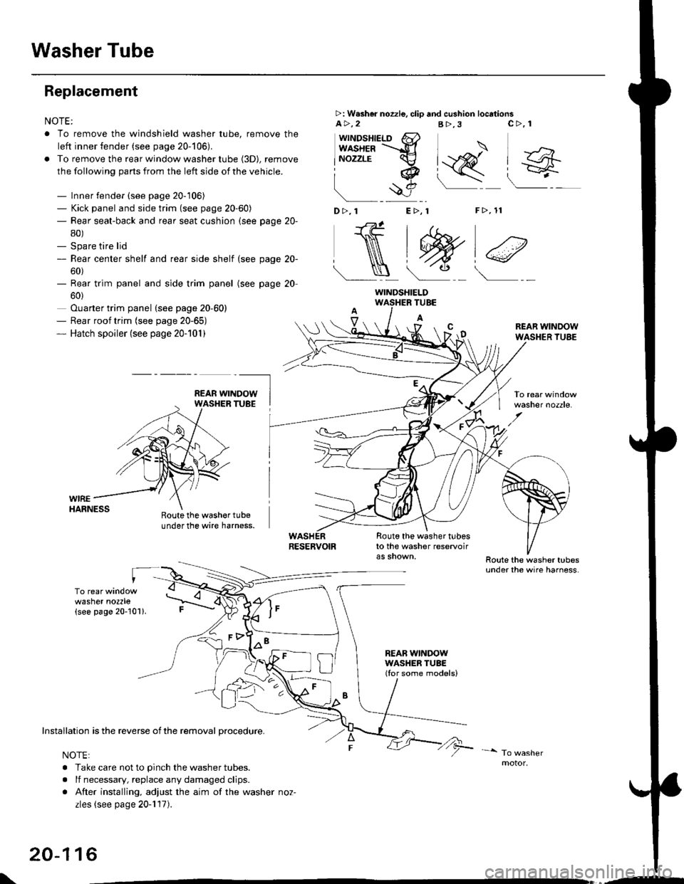
Washer Tube
Replacement
NOTE:
. To remove the windshield washer tube, remove the
left inner fender (see page 20-106),
. To remove the rear window washer tube {3D), remove
the following parts from the left side of the vehicle.
- Inner fender (see page 20-106)- Kick panel and side trim (see page 20-60)- Rear seat-back and rear seat cushion (see page 20-
80)- Spare tire lid- Rear center shelf and rear side shelf (see page 20-
60)- Rear trim panel and side trim panel
60)
Ouarter trim panel (see page 20-60)- Rear roof trim {see page 20-65)- Hatch spoiler (see page 20-101)
(see page 20
WIREHARNESS
>: W.sher nozzle, clip and cushion locationsa>,2B>,3
"J>)
[q@"
F>, 11
c>, 1
wttrtosnteLo 6}usxea =-d
lNozzrE cv
iq
!$e
D>,1 E>, 1
NtW)€
Roote the washer tubeunder the wire harness.
TUBE
A
Route the washer tubesto the washer reservoir
REAB WINDOWWASHER TUBE(Ior some models)
REAR WINDOWWASHER TUBE
washer nozzle.
washer nozzle(see page 20-101).
oo\
Installation is the reverse of the removal procedure.
NOTE:
. Take care not to pinch the washer tubes.
. lf necessary, replace any damaged clips.
. After installing, adjust the aim of the washer noz-
zles (see page 20-117).
20-116
WINDSHIELD
\,--
Page 1359 of 2189
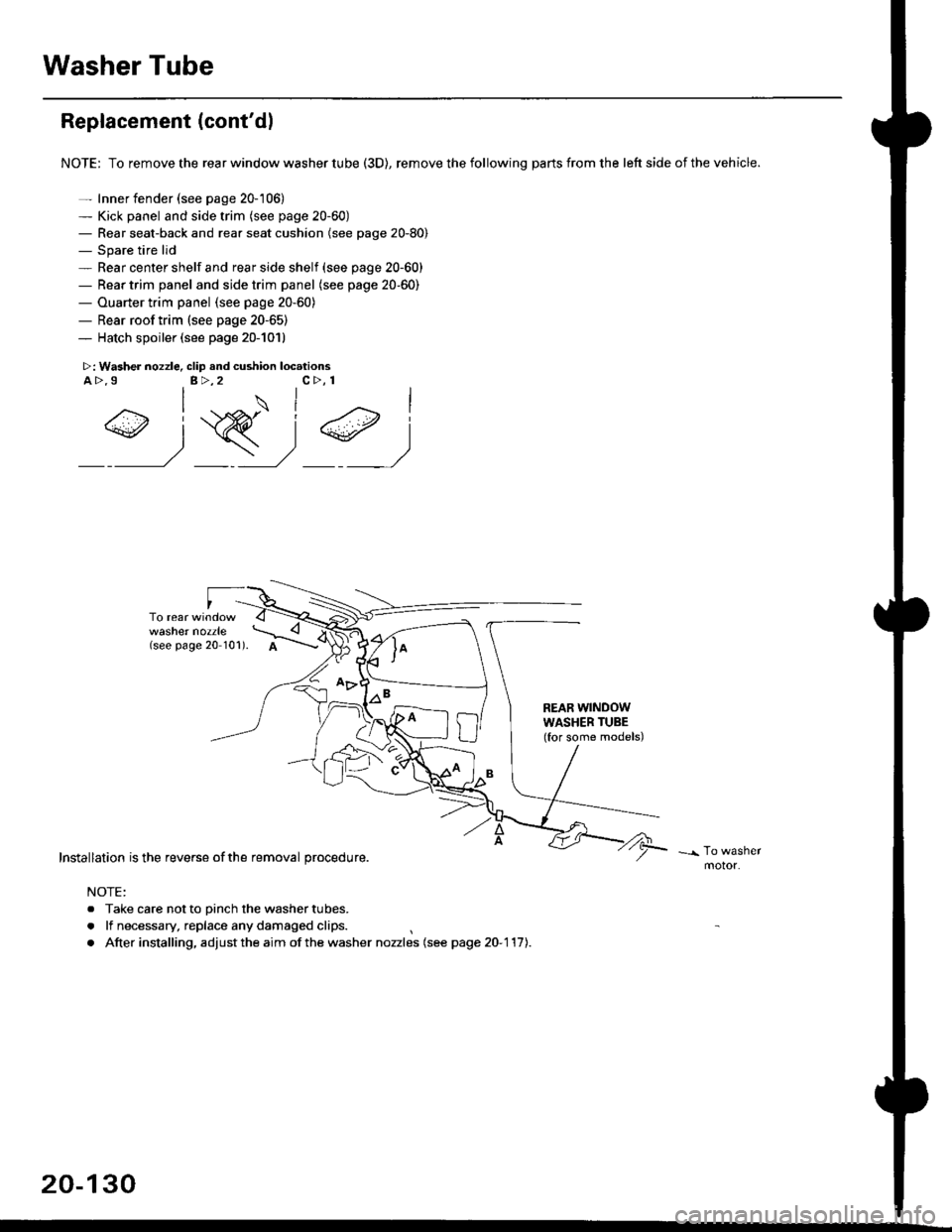
Washer Tube
Replacement (cont'dl
NOTE: To remove the rear window washer tube (3D), remove the following parts from the left side of the vehicle.
- Inner fender (see page 20-'106)- Kick panel and side trim (see page 20-60)- Rear seat-back and rear seat cushion (see page 20-80)- Spare tire lid- Rear center shelf and rear side shelf (see page 20-60)- Rear trim panel and side trim panel (see page 20-60)- Ouarter trim panel (see page 20-60)- Rear roof trim (see page 20-65)- Hatch spoiler (see page 20-1011
>: Washer nozzle, clip and cushion locationsA >.9 B>,2 C>, 1
I sl -..._, 1
aj\
(see page 20 101).
REAR WINDOWWASHER TUBE(for some models)
Installation is the reverse ofthe removal procedure.
NOTE:
. Take care not to pinch the washer tubes.
. lf necessary, replace any damaged clips.
. After installing, adjustthe aim ofthe washer nozzles (see page2O-1111.
motor.
20-130
Page 1486 of 2189

Connector ldentification and Wire Harness Routing
Engine Wire Harness lD16Y5, D16Y8 enginss): '96 - 98 models
Connector or
Torminal
Numbsr of
CavitissLocationConnects toNot€s
c 101c102c103c104c104c105c106c107c108c 109c110c111c112c113c114c115c116cl17c118c119c120cl21
c122c123cl23c124
c125
c127c12Ac129c130c131c132c 133c134c135
c136
c138c139c140c 141c142c 143c144cl44c145c'146cl47
10
1
22
14l4322l0I
2
2
2
2120
3l
14
14
1222
2
2
22
Left side of engine compartmentMiddle of engineMiddle of engineLeft side of engine companmentLeft side of engine compartmentMiddle of engineMiddle of engineMiddle of engineMiddle of engineMiddle of enginefvliddle of engineMiddle of engineMiddle of engineMiddle of engineMiddle of engineMiddle of engineMiddle of engineLeft side of engine compartmentMiddle of engineMiddle of engineMiddle of engineMiddle of engine
Middle of engineMiddle of engineMiddle of engineMiddle of engineMiddle of engineMiddle of engineMiddle of engineMiddle of engineMiddle of engineRight side of engine companmentBehind right kick panelUnder right side of dashUnder riOht side of dashUnder right side of dashUnder right side of dashUnder right side of dashUnder right side of dash
Under right side of dash
Under right side of dash
Middle of engineMiddle ot enginel iddle of engineMiddle of engineMiddle of ongineMiddle of engineLeft side of engine compartmentMiddle of engineMiddle of engineRight side of engine compartmentRight side of engine compartmentRight side of engine compartment
USACanada
Afi
USA
-' (A/r)
Main wire harness (C303)Crankshaft speed fluctuation (CKF) sensorEngine oil pressure switchAlternatorAlternatorNo. 'l fuel injectorNo. 2 fuel injectorNo.3 fuel injectorNo. 4 fuel injectorIAC valveThrottle position (TP) sensorl\4anifold absolute pressure (MAP) sensorIntake air temperature (lAT) sensorPower steering pressure {PSPI switchEVAP purge control solenoid valveJunction connectorJunction conn€ctorVehicle speed sensor {VSS}Countershaft speed sensorEngine coolant temp€rature (ECT) switch ADistributorEngine coolant temperature (ECT) sendingunrtEngine coolant temperature (ECT) sensorPrimary HO2S (sensor'l)Primary HO2S (sensor 1)Back-up light switchLock-up control solenoid valveSecondary HO2S (sensor 2)Mainshaft speed sensorLinear solgnoid valveShift control solsnoid valveStarter solenoidJunction connectorMain wire harnesE (C446)ECM/PCMPCMECMiPCMECM/PCMMain wire harness (C305)
Main wire harness (C305)
Main wire harness (C305)
Knock sensor (KS)IAC valveVTEC solenoid valveVTEC pressure switchEVAP control canister vent shut valveEGR control solenoid valveSecondary gear shaft speed sensorEGR valveEGR valveDrive pulley speed sensorSolenoid connector {CVT)Driven pulley speed sensor
*, (M/T)M/T*" INT\
*, tAtf)
NT:'96 model*,(A,/T):'97 - 98mooets
moqets
M/T
-1 (l,/T)*, (A,/T)-,(4,/T)*1 {M/T)*, (A,/T)*1 (CW)*, (A,T)
T101r102Left side of engine companmentRight side of engine companmentAlternatorUnder-hood fuse/relay boxG 101Middle of engineEngine ground, via engine wire harness
2
*1: Dl6Y5 engine*2: D16Y8 engine*3: D16Y5 (Ay'T), D16Y8 engines
3-16