Page 1151 of 2189
IDisassembly/lnsPection
lr
Disassembly
1. Compress the damper spring with the spring com-
pressor according to the manufacturer's instruc-
tions, then remove the self-locking nut.
GAUTION: Do not compress the spring more than
necessary to remove the sell-locking nut.
STNUT SPRING COMPRESSOR:
lComm6rcially .vailablelERANICKo T/N MST-580A, T/N 7200, or equivalent
Release the pressure from the spring compressor.
then disassemble the damper as shown on page 18-
(|-r
lnspection
1. Reassemble all parts, except the sprlng.
2. Push on the damPer as shown.
WOODEN BLOCK
Check for smooth operation through a full stroke,
both compression and extension.
NOTE: The damper should move smoothly lf it
does not (no compression or no extension), the gas
is leaking, and the damper should be replaced.
Check Jor oil leaks, abnormal noises, and binding
during these tests.
{cont'd)
18-27
Page 1152 of 2189
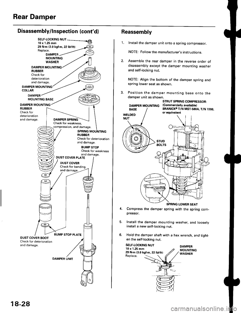
Rear Damper
Disassembly/lnspection (cont'dl
SELF-LOCK|NG NUT - el10 x 1.25 mm v
29 N.m {3.0 kst'm, 22 lbf.ftlReplace.
DAMPEBMOUNTINGWASHER
DAMPER MOUNTING8U8BERCheck tordeteriorationano oamage.
DAMPERCOLLAR
DAMPERMOUNTING BASE
OAMPER MOUNTING
DAMPER SPRINGCheck lor weakness,compression, and damage.
SPRING MOUNTINGRUBBERCheck for deteriorationano oamage.
BUMP STOPCheck for weaknessand damage,
BUBBESCheck fordeteriorationano oamage.
OUST COVER PLATE
DUST COVERCheck lor bending
DUST COVER BOOTCheck for deteriorationand damage.
18-2A
OAMPER UNITReplace. :
Reassembly
1.Install the damper unit onto a spring compressor.
NOTE: Followthe manufacturer's instructions.
Assemble the rear damper in the reverse order ofdisassembly except the damper mounting washer
and self-locking nut.
NOTE: Align the bottom of the damper spring andspring lower seat as shown.
Position the damper mounting base onto thedamoer unit as shown.
SIRUT SPRING COMPRESSOR:
DAMpERMOUNTTNG (Commerciattyavaitabtel
BRANICKO T/N MST-580A, T/N 7200.or cquivalont
Compress the damper spring with the spring com-pressor.
Install the damper mounting washer, and looselyinstall a new self-locking nut.
Hold the damper shaft with a hex wrench, and tight-en the self-locking nut.
SELF-LOCKING NUTDAMPER10 x 1,25 mm29 N m 13.0 kgt.m, 22 lbtftlMOUNTINGWASHER
Page 1158 of 2189
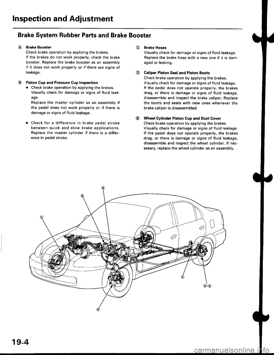
Inspection and Adjustment
€)
@
@
@
Brake System Rubber Parts and Brake Booster
Brake Boostet
Check brake operation by applying the brakes.
lf the brakes do not work properly, check the brake
booster, Replace the brake booster as an assembly
if it does not work properly or if there are signs of
leakage.
Piston Cup and Pressure Cup Inspeqtion
. Check brake operation by applying the brakes.
Visually check for damage or signs of fluid leak-
age.
Replace the master cylinder as an assembly if
the pedal does not work properly or if there is
damage or signs of fluid leakage.
. Check for a difference in brake pedal stroke
between quick and slow brake applications.
Replace the master cylinder if there is a differ-
ence in oedal stroke.
Brake Hoses
Visually check for damage or signs of fluid leakage.
Replace the brake hose with a new one if it is dam-
aged or leaking.
Caliper Piston Seal and Piston Boots
Check brake ope.ation by applying the brakes.
Visually check for damage or signs of fluid leakage.
lf the pedal does not operate properly, the brakes
drag. or there is damage or signs of fluid leakage,
disassemble and inspect the brake caliper. Replace
the boots and seals with new ones whenever the
brake caliDer is disassembled.
Wheol Cylindor Piston Cup and Dust Cover
Check brake operation by applying the brakes.
Visually check for damage or signs of fluid leakage.
lf the pedal does not operate properly, the brakes
drag, or there is damage or signs of fluid leakage,
disassemble and inspect the wheel cylinder. lf nec-
essary, replace the wheel cylinder as an assembly.
19-4
Page 1160 of 2189
Inspection and Adjustment
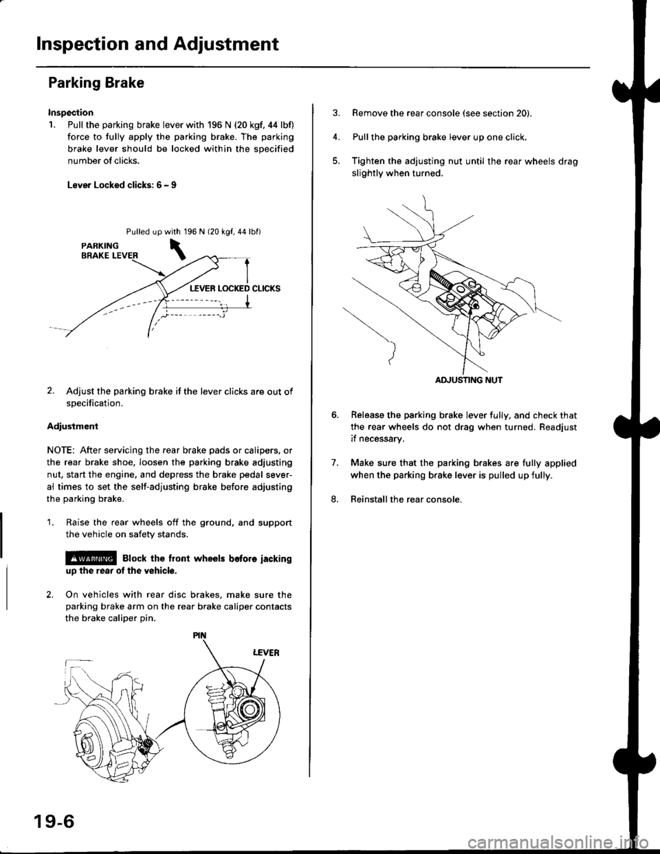
Parking Brake
Inspection
1. Pull the parking brake lever with 196 N {20 kgf. 44 lbf)
force to fully apply the parking brake. The parking
brake lever should be locked within the sDecified
number of clicks.
Lever Locked clicks: 6 - I
Pulled up96 N 120 kgf,44lbf)
2. Adjust the parking brake if the lever clicks are out of
specification.
Adiusiment
NOTE: After servicing the rear brake pads or calipers, or
the rear brake shoe, loosen the parking brake adjusting
nut, start the engine, and depress the brake pedal sever-
al times to set the self-adjusting brake before adjusting
the parking brake.
1. Raise the rear wheels off the ground, and support
the vehicle on safety stands.
l@ Elock the front wheels bofore iackinguD the rear ot the v6hicle.
2. On vehicles with rear disc brakes, make sure theparking brake arm on the rear brake caliper contacts
the brake calioer Din.
with 1
\
19-6
Remove the rear console (see section 20).
Pullthe parking brake lever up one click,
Tighten the adjusting nut until the rear wheels drag
slightly when turned.
Belease the parking brake lever fully, and check that
the rear wheels do not drag when turned. Readjust
if necessarv.
Make sure that the parking brakes are fully applied
when the parking brake lever is pulled up fully.
Reinstall the rear console.
7.
8.
ADJUSTING NUT
Page 1161 of 2189
I
Bleeding
CAUTION:
. Always use Genuine Honda DOT 3 Brake Fluid. Using 8
non-Honda brak€ fluid can cause corrosion and
docrea3e the life of the system.
. Make surs ||o dirt or other foteign matter is allowed
to contaminate the brake fluid,
. Do not spill brake lluid on the vehicle, it may damago
the paint; if brake lluid doos contac{ the paint, wash
it ofl imm€diately with water.
NOTE: The reservoir on the master cylinder must be at
the MAX (upper) level mark at the start of the bleeding
procedure and checked after bleeding each brake
caliper. Add fluid as required.
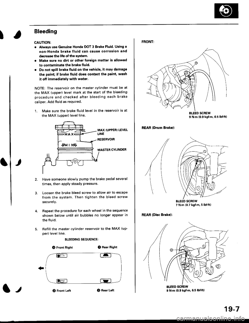
1. Make sure the brake fluid level in the reservoir is at
the MAX lupper) level line.
MAX {UPPER) LEVEL
CYLINDER
Have someone slowly pump the brake pedsl several
times, then apply steady Pressure.
Loosen the brake bleed screw to allow air to escape
from the system. Then tighten the bleed screw
securely.
Repeat the procedure for each wheel in the sequence
shown below until air bubbles no longer appear in
the fluid.
Refill the master cylinder reservoir to the MAX (up-
per) level line.
ELEEDING SEOUENCE:
O Front Right(D Bo.r Right
O Front LeftO Rear Left1,,
19-7
FRONTT
REAR lDrum Brakel:
REAR (Disc Brake):
AIEED SCREW9 N.m (0.9 ksf m, 6.5 lbf'ft)
Page 1162 of 2189
Front Brake Pads
Inspection and Replacement
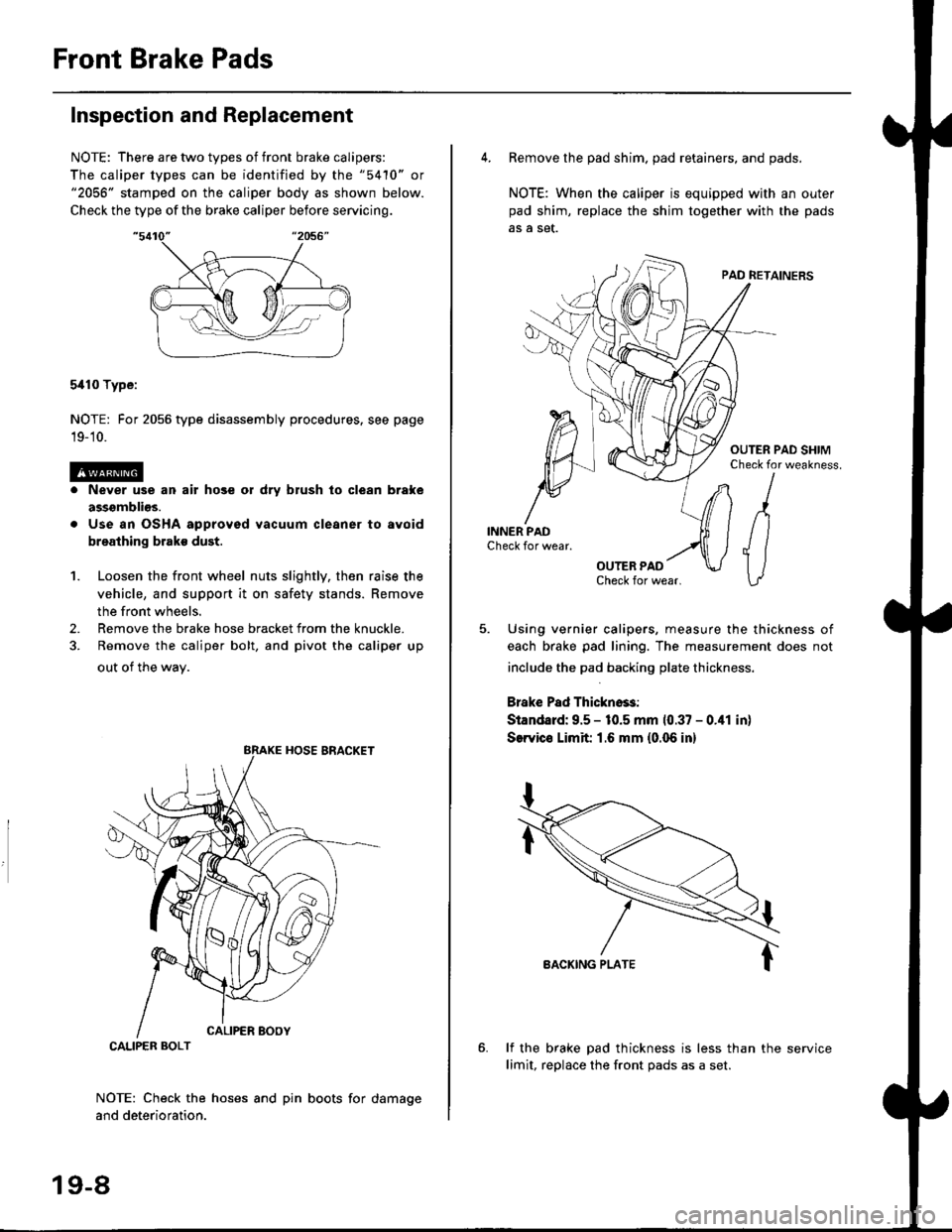
NOTE: There are two types of front brake calipers:
The caliper types can be identified by the "5410" or"2056" stamped on the caliper body as shown below.
Check the type of the brake caliper before servicing.
5i110 Type:
NOTE: For 2056 type disassembly procedures. see page
19-'10.
Never use an air hose or dry brush lo clean brake
assgmblios.
Use an OSHA approved vacuum cleaner to avoid
breathing brake dust.
Loosen the front wheel nuts slightly, then raise the
vehicle, and support it on safety stands. Remove
the front wheels.
Remove the brake hose bracket from the knuckle.
Remove the caliper bolt, and pivot the caliper up
out of the wav.
1.
2.
NOTE: Check the hoses and pin boots for damage
and deterioration.
CALIPER BOLT
19-8
4. Remove the pad shim. pad retainers, and pads.
NOTE: When the caliper is equipped with an outer
pad shim, replace the shim together with the pads
5. Using vernier calipers, measure the thickness of
each brake pad lining. The measurement does not
include the pad backing plate thickness.
Brake Pad Thickno$:
Standard: 9.5 - 10.5 mm 10.37 - 0.41 in)
SerYico Limit 1.6 mm {0.06 in}
lf the brake pad thickness is less than the service
limit, replace the front Dads as a set.
Page 1163 of 2189
)
It
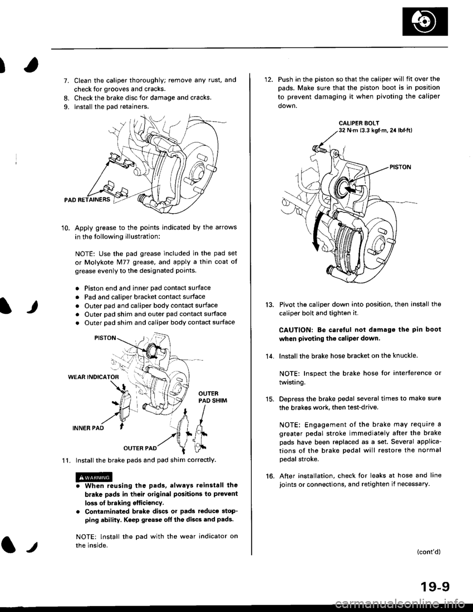
7. Clean the caliper thoroughly; remove any rust, and
check for grooves and cracks.
8. Check the brake disc for damage and cracks.
9. lnstall the pad retainers,
10. Apply grease to the points indicated by the arrows
in the following illustration:
NOTE: Use the pad grease included in the pad set
or Molykote Nl77 grease, and apply a thin coat of
grease evenly to the designated points.
o Piston end and inner Dad contact surface
. Pad and calioer bracket contact surface
. Outer pad and caliper body contact surface
. Outer pad shim and outer pad contact surface
. Outer pad shim and caliper body contact surface
WEAR INDICATOB
INNER PAD
OUTER PAD
1 1. Install the brake pads and pad shim correctly.
. Whon reusing the pads, always reinstall the
brake pads in their original positions to prevont
loss of braking efticiency.
. Contaminated brake discs or pads teduce stop-
ping ability. Keep grease oft the discs and pads'
NOTE: lnstall the Dad with the wear indicator on
the inside.l.t
'12. Push in the piston so that the caliper will fitoverthe
pads, Make sure that the piston boot is in position
to prevent damaging it when pivoting the caliper
down.
Pivot the caliper down into position, then install the
caliper bolt and tighten it.
CAUTION: Be caretul not damage the pin boot
when pivoting the caliper dowr.
lnstall the brake hose bracket on the knuckle
NOTE: Inspect the brake hose for interference or
twisting.
Depress the brake pedal several times to make sure
the brakes work. then test-drive.
NOTE: Engagement of the brake may require a
greater pedal stroke immediately after the brake
pads have been replaced as a set. Several applica-
tions of the brake pedal will restore the normal
Dedal stroke.
After installation. check for leaks at hose and line
joints or connections, and retighten if necessary.
13.
14.
15.
16.
(cont'd)
19-9
CALIPER BOLTN m (3.3 kgf m,2a lbf.ft)
Page 1164 of 2189
Front Brake Pads
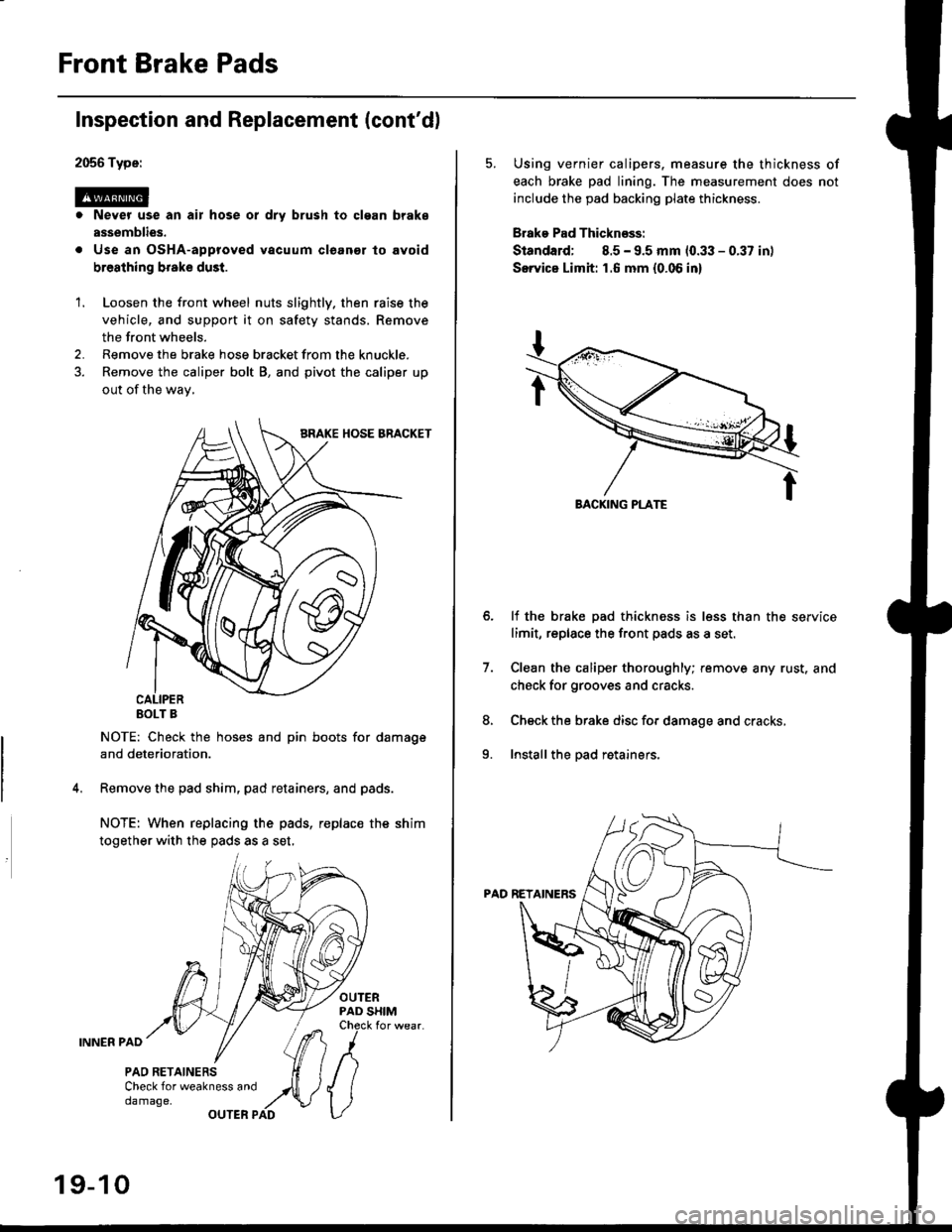
2056 Type:
@. Never use an air hose or dry brush to clgan brake
assemblies.
. Use an OsHA-approved vacuum cleanor lo avoid
breathing broke dust.
Inspection and Replacement (cont'dl
1. Loosen the front wheel nuts slightly. then raise the
vehicle, and support it on safety stands. Remove
the front wheels.
2. Remove the brake hose bracket from the knuckle.
3. Remove the caliper bolt B, and pivot the caliper up
out of the wav,
EOLT B
NOTE: Check the hoses and pin boots for damage
and deterioration.
Remove the pad shim, pad retainers, and pads.
NOTE: When replacing the pads, replac€ the shim
together with the pads as a set,
OUTERPAD SHIMCheck for wear.
INNER PAD
PAO RETAINERSCheck for weakness anddamage,OUTER PAD
19-10
5. Using vernier calipers. measure the thickness of
each brake pad lining. The measurement does not
include the pad backing plate thickness.
Brake Pad Thicknsss:
Standard; 8.5 - 9.5 mm 10.33 - 0.37 in)
Servica Limh: 1.6 mm {0.06 in}
lf the brake pad thickness is less than the service
limit, replace the front pads as a set,
Clean the caliper thoroughly; remove any rust. and
check for grooves and cracks.
Check the brake disc for damage and cracks,
Install the pad retainers.
7.
8.
9.