1997 HONDA CIVIC Clutch pressure Control
[x] Cancel search: Clutch pressure ControlPage 915 of 2189

Symptom-to-Component Chart
Electrical System -'96 - 98 Models
*: The DTC in parentheses is the code @ indicator light indicates when the Data Link Connector is connected to the HondaPGM Tester.
DTC*O Indicator
LightMILDetection ltemPage
P1790
(3)BlinksONThrottle position sensor14-242
P179'l
(4)BlinksONVehicle speed sensor14-243
P1705
(5)BlinksONAy'T gear position switch (short to groundl't 4-244
P1706
(6)OFFONA/T gear position switch {open)14-246
P0725
(11)BlinksONlgnition coil14-248
P1793
112lBlinksONManifold absolute pressure sensor14-249
P 1870(30)BlinksONShift control linear solenoid14-250
P'1873
(311BlinksONPH-PL control linear solenoid14-25'l
P1879(32)BlinksONStart clutch control linear sotenoid14-252
P1882BlinksONInhibitor solenoid14-253
P1885
(34)BlinksONDrive pulley speed sensor1l-Zb4
P1886(35)BlinksONDriven pulley speed sensor14-255
P1888
(36)BlinksONSecondary gear shaft speed sensor14-256
T to55
(37)BlinksONECM or TCM14-257
P1890
l42lBlinksONShift control system14-259
P1891
(43)BlinksONStart clutch control svstem14-260
14-23a
Page 970 of 2189
Start Clutch Control@
T
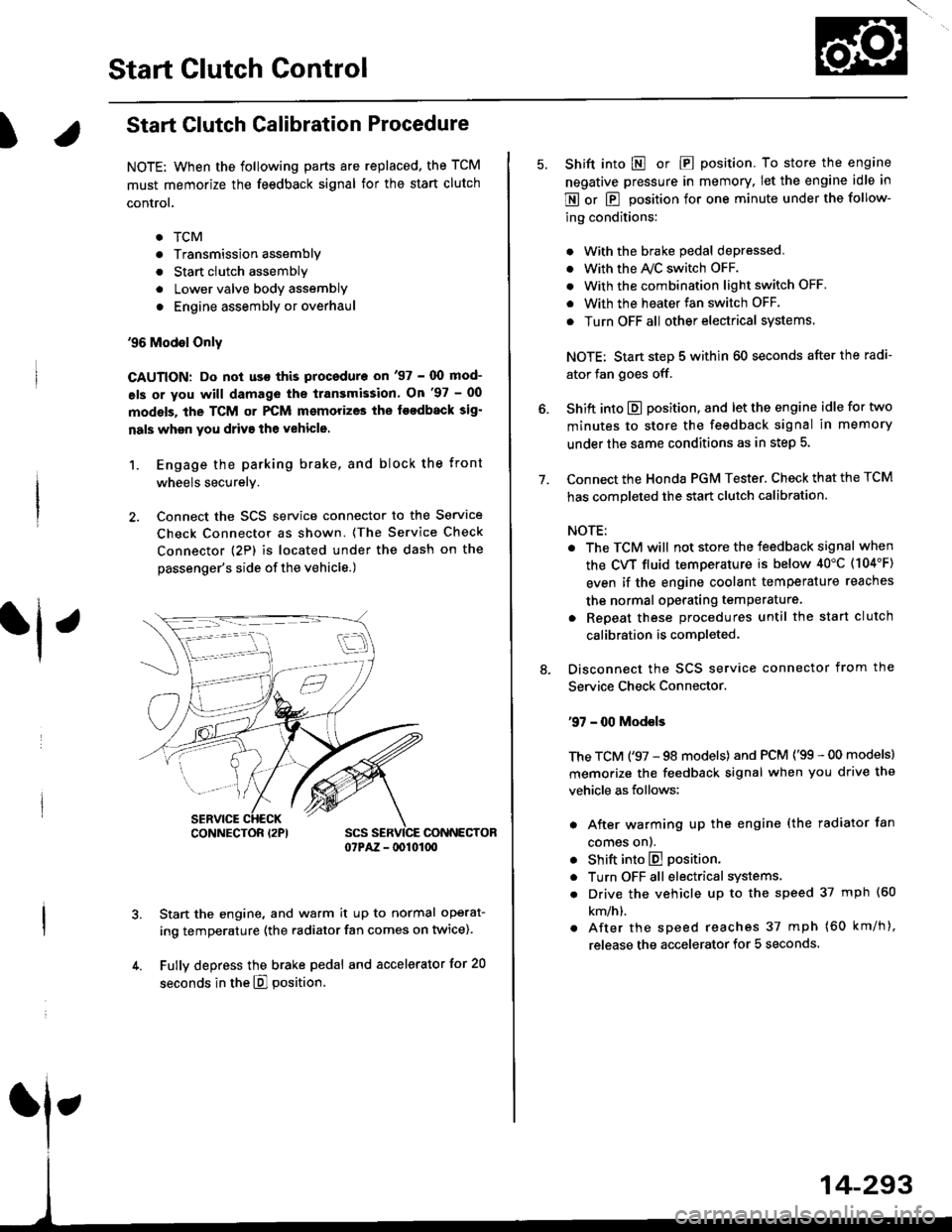
Start Clutch Calibration Procedure
NOTE: When the following parts are replaced, the TCM
must memorize the feedback signal for the start clutch
control.
. TCM
. Transmissionassembly
. Stan clutch assembly
. Lower valve bodv assembly
. Engine assembly or overhaul
'96 Model Only
CAUTION: Do not uso this procsdure on'97 - (X) mod-
els or you will damage the transmission. On '97 - 00
models, the TCM or PCM memorizes ths loodback sig'
nals when you drive the vehicle.
1. Engage the parking brake, and block the front
wheels securely.
2. Connect the SCS service connector to the Service
Check Connector as shown. (The Service Check
connector (2P) is located under the dash on the
passenger's side of the vehicle.)
CONNECTOR07PAZ - lDl01(xt
Start the engine, and warm it up to normal operat-
ing temperature (the radiator fan comes on twice).
Fully depress the brake pedal and accelerator for 20
seconds in the E] position.
rl ,
CONNECTOR I2PI
14-293
7.
Shift into E o|. E position. To store the engine
negative pressure in memory. Iet the engine idle in
E or E position for one minute under the follow-
ing conditions:
. With the brake pedal depressed,
. with the y'\/c switch oFF.
. With the combination light switch OFF.
. With the heater fan switch OFF.
. Turn OFF all other electrical systems
NOTE: Start step 5 within 60 seconds after the radi-
ator fan goes off.
Shift into E position, and let the engine idle for two
minutes to store the feedback signal in memory
under the same conditions as in step 5.
Connect the Honda PGM Tester. Check that the TCM
has completed the start clutch calibration.
NOTE:
. The TCM will not store the feedback signal when
the CVT fluid temperature is below 40"C (104'F)
even if the engine coolant temperature reaches
the normal operating temperature.
. Repeat these procedures until the start clutch
calibration is completed-
Disconnect the SCS service connector from the
Service Check Connector.
'97 - 00 Models
The TCM ('97 - 98 models) and PCM ('99 - 00 models)
memorize the feedback signal when you drive the
vehicle as follows:
. After warming up the engine (the radiator fan
comes onl.
. Shift into E position.
. Turn OFF all electrical systems,
. Drive the vehicle up to the speed 37 mph (60
km/h).
. After the speed reaches 37 mph (60 km/h),
release the accelerator for 5 seconds.
Page 972 of 2189
t.
rl,
fl,
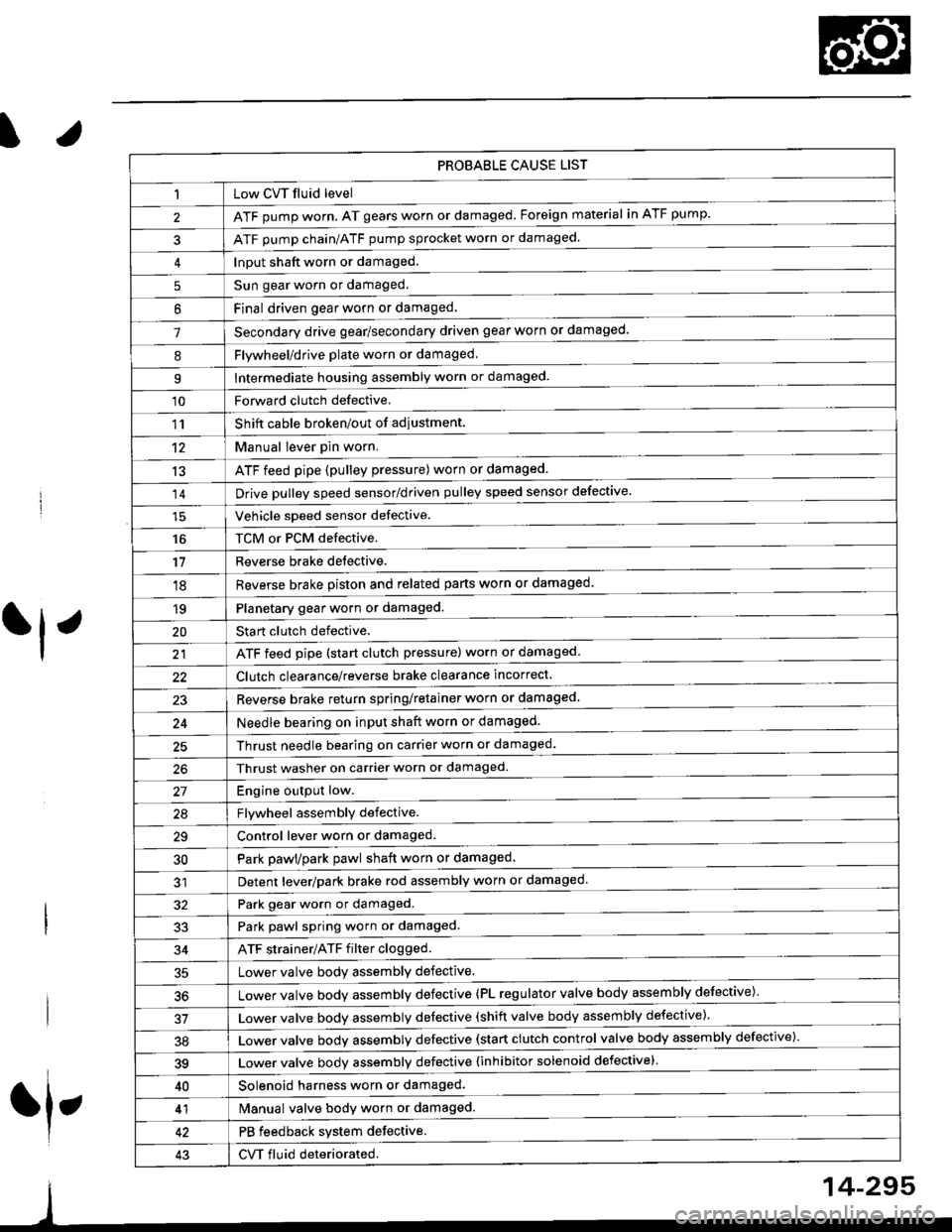
PROBABLE CAUSE LIST
Low CVT fluid level
ATF pump worn. AT gears worn or damaged. Foreign material in ATF pump.
ATF pump chain/ATF pump sprocket worn or damaged.
Input shaft worn or damaged.
Sun gear worn or damaged.
Final driven oear worn or damaqed,
Secondary drive gear/secondary driven gear worn or damaged-
5
6
1
8Flywheel/drive plate worn or damaged.
Intermediate housing assembly worn or damaged.9
'10Forward clutch defective.
Shift cable broken/out of adiustment.
M"nu"t t"uffi
ATF feed pipe (pulley pressure) worn or damaged.
Vchiclc speed sensor defective.
TCM or PCM defective.
Reverse brake detective.
1'�r
't2
13
14
16
'11
'18
1qPlanetary gear worn or damaged.
Sta rt clutch defective.
ATF feed pipe (start clutch pressure) worn or damaged
20
t't
Clutch clearance/reverse brake clearance incorrect.
23Reverse brake return spring/retainer worn or damaged
24Needle bearing on input shaft worn or damaged.
25Thrust needle bearing on carrier worn or damaged.
Thrust washer on carrier worn or damaged.
Enoine outout low.------------------------
Flvwhcel assemblv defective.
Control lever worn or damaged.
Park pawl/park pawl shaft worn or damaged
Detent lever/park brake rod assembly worn or damaged
27
29
30
32Park gear worn or damaged.
Park pawl spring worn or damaged.
ATF strainer/ATF filter clogged.
Lower valve body assembly defective.
Lower valve bodv assemblv defective (PL regulator valve body assembly defective)'
33
34
50
Lower valve bodv assembly defective (shift valve body assembly defective).
Lower valve bodv assemblv defective (start clutch control valve body assembly defective)'
39Lower valve bodv assemblv defective {inhibitor solenoid defective}
40Solenoid harness worn or damaged.
Manual valve body worn or damaged.
PB feedback system defective.
CVT fluid deteriorated.
41
43
14-295
Page 978 of 2189

1.
Start the engine.
Shift to the respective shift lever positions in the table, and measure the following pressures at 1'500 rpm'
. Forward Clutch Pressure
. Reverse Brake Pressure
. Drive Pulley Pressure
. Driven Pulley Pressure
8. Shift to E posltion, and measure the lubrication pressure at 3,000 rpm'
Disconnect the special tool after pressure testlng
Install the sealing boits in the jnspection holes with new sealing washers, and tighten the bolts to the specified
toroue.
TOROUE: 18 N.m {1.8 kgf'm, 13 lbf'ft}
CAUTION: Keep all foreign particles out of the transmission'
9.
10.
PBESSURESHIFT LEVER
POSmONSYMP{OMPROBABLE CAUSE
FLUID PRESSURE
Standard/Ssrvice Limit
Forwa rd
Clutch
ENo or low for-
ward clutch
pressure
Forward Clutch1.4 - 1.75 MPa
(14.3 - 17.8 kgtcm'�, 203 - 253 Psi)
Reverse
Brake
tsNo or low
reverse brake
pressure
Reverse Brake1.4 - 1.75 MPa
(14.3 - '17.8 kg7cm'�, 203 - 253 Psi)
Drive
Pulley
NNo or low
drive pulley
pressure
ATF pump, PH reg-
ulator valve, PL
regulator valve,
Shift valve
0.2 - 0.7 MPa
(2 - 7.1 kgflcm'�, 28 - 101 Psi)
Drive pulley
pressure roo
high
PH regulator valve,
PL regulator valve,
Shift valve. Shift
control linear
solenoid
Driven
Pulley
No or low
driven pulley
pressure
ATF pump, PH reg-
ulator valve, Shift
valve, Shift control
linear solenoid
1.5 - 2.3 MPa
(15.3 - 23.5 kg?cm'�, 218 - 334 Psi)
Driven pulley
pressure too
h igh
PH regulator valve
LubricationNo or low
lubrication
pressure
ATF pump,
Lubrication valve
Above 0.2 MPa
(Above 2 kgf/cm'�. 30 Psi)
14-301
Page 996 of 2189
l.
1.
2.
Remove the end cover {three 6 mm bolts, eleven 8
mm bolts).
Remove the manualvalve body lines A and B
3. Remove the snap ring securing the ring gear, then
remove the thrust shim and the ring gear'
4. Remove the snap ring securing the reverse brake
discs and plates, then remove the reverse brake end
plate. brake discs, brake plates, and disc spring'
5. Remove the carrier with the thrust washers and the
thrust needle bearing from the forward clutch
6. Remove the sun gear and the input shaft as a sub
assembly bY Pulling it
The sun gear is press fitted tightly into input shaft'
7. Remove the snap ring securing the forward clutch,
and remove the snap ring securing the forward clutch
end plate, then remove the forward clutch end plate'
8. Reinstall the carrier on the forward clutch, then
secure the carrier with the snap ring on the forward
clutch end Plate.
9. Remove the forward clutch and carrier assembly
together.
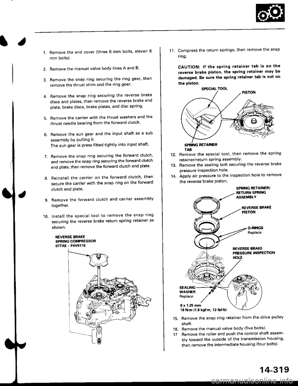
'10. lnstall the special tool to remove the snap ring
securing the reverse brake return spring retainer as
snown.
REVERSE BBAKESPRING COMPRESSOR07TAE - PaV0110
11. Compress the return springs. then remove the snap
ring
CAUTION: lf the spring retainer tab is on the
rsverse braks piston, tho spting letainer may be
damaged. Be surs the spring letainer tab is not on
the piston.
SPfiING FETAIiGRTAB
Remove the special tool, then remove the spring
retainer/return spring assembly.
Remove the sealing bolt securing the reverse brake
pressure insPection hole.
Apply air pressure to the inspection hole to remove
the reverse brake Piston
12.
13.
14.
16.'t7
SPBING REYAINER/RETURiI SPRIiIGASSEMALY
REVERSE BNAXEPISTON
o-RrllcsReplace.
FCVERSE BRAKEPRESSURE INS?ECTK)NHOtl
SEALINGWASHERReplace.
8 x 1.25 mm18 N.m 11.8 kgf.m, 13 lbf.ttl
Remove the snap ring retainer from the drive pulley
shaft.
Remove the manual valve body (five bolts)'
Remove the roller and push the control shaft assem-
bly toward the outside of the transmission housing,
then remove the intermediate housing (four bolts)'
SPECIAL TOOL
14-319
Page 1429 of 2189
Description
Outline
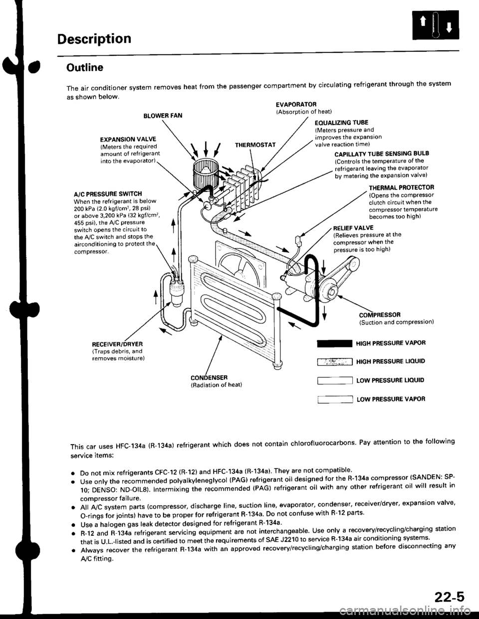
The air conditioner system removes heat from the passenger compartment by circulating refrigerant through the system
as shown below.
BLOWER FAN
EVAPORATOR(Absorption of heati
EOUALIZING TUBE(Meters pressure andimproves the expansionvalve reaction time)
into the evaporator)CAPILLATY TUBE SENSING BULB
lControls the temPerature of the
ref rigerant leaving the evaporator
by metering the expansion valve)
/\
THERMOSTAT
A/C PRESSURE SWITCH
When the refrigerant is below
200 kPa (2.0 kgtcm'�,28 Psi)or above 3,200 kPa 132 kgflcm',
455 psi), the Ay'C pressure
switch opens the circuit to
the A,/C switch and stops the
EXPANSION VALVE(Meters the requiredamount of refrigerant
airconditioning to Protect the
compressor.
RECEIVER/DRYER(Traps debris, andremoves morsturel
THERMAL PROTECTOR
{Opens the comPressorclutch circuit when the
compressor temPeraturebecomes too high)
RELIEF VALVE(Relieves pressure at the
compressor when thepressure is too high)
(Radiation of heat)
I
f-r-�-; I
(Suction and comPression,
HIGH PRESSURE VAPOR
HtGH PRESSUBE LIOUID
LOW PRESSURE LIOUID
This car uses HFC-134a (R-134a) refrigerant which does not contain chlorofluorocarbons Pay attention to the following
service items:
. Do not mix refrigerants CFC-12 (R-12) and HFC-134a (R-134a)' They are not compatible'
. Useonlythe recommended polyalkyieneglycol (PAG) refrigerant oil designedforthe R-134a compressor (SANDEN: SP-
10; DENSO: ND_OIL8). Intermixing ihe re-commended (pAG) refrigerant oil with any other refrigerant oil will result in
compressor failure.
. All A,,ic system parts {compressor, discharge line, suction line, evaporator, condenser, receiver/dryer, expansion valve'
O-rings for joints) have to be proper for refrigerant R- 134a Do not confuse with R-l2 parts'
. Use a halogen gas leak detector designed for refrigerant R-134a
. R-12 and R-134a refrigerant servacing equipment are not interchangeable. Use only a recovery/recycling/charging station
that is u,L.-listed and is certified to meet the requirements of sAE J2210 to service R-134a air conditioning systems'
. Always recover the refrigerant R-134a with an approved recovery/recycling/charging station before disconnecting any
A,/C fitting.
S]
22-5
Page 1840 of 2189

Ground-to-Components I ndex
f.,lONOTE: All ground wires are BLK unless otherwise noted.
GroundPageComponents or Circuit Grounded
Battery (BLKYEL)
Steering pump bracket
t+-rg ITransmission housing
l
G101
(-1)
G101
(-2)
14-2
and
14-3
ano
14-1
Powertrain or engine control module (PG1 and pG2 are BLK: LG1 and LG2 are
BRN/BLK), EGR control solenoid valve (CW, EGR valve and lift sensor (Dt6yS enginewith M,/T), Engine coolant temperature switch, pGM-Fl main relay, power steeringpressure switch (USA), Primary HO2S (D16Y5 engine with l\/,/T), Vehicle speed sensor,VTEC pressure switch (D16Y5/D16Y8 engines), CKF sensor (BRN/BLK), Transmission
control module (CYf) (Pc1 is BLK: LG1 is BRN/BLK)
Shielding betvveen the PCM or ECM and these components (all have BRN/BLK wires):
CKF sensor, TDC/CKP/CYP sensor. Primary and secondary heated oxygen sensors.
Knock sensor (CWDl6YB engine), Mainshaft speed sensor (AiT except CVT),
I Countershaft speed sensor (A/T except CVf)
Shielding between the TCM and these components (CVT) (all have BRN/BLK wires):
Drive pulley speed sensor, Driven pulley speed sensor, Secondary gear shaft
speed sensor
Powertrain or engine control module (PG1 and pG2 are BLK; LG1 and LGz are
BRN/BLK), EGR control solenoid valve (D16Y5 engine), EGR valve (Dt685), Engine
coolant temperature switch, Fuel pressure regulator shut-off solenoid valve (D1685),
PGM-FI main relay, Power steering pressure switch (USA), Vehicle speed sensor, VTECpressure switch (All except D16Y7 engine), CKF sensor (A
except 81642) (BRN/BLK)
Shielding between the PCM or ECM and these components (all have BRN/BLK wires):
CKF sensor, TDC/CKP/CYP sensor, Primary and secondary heated oxygen sensors,
Knock sensor (All except D16Y7 engine), i/ainshaft speed sensor (Arf except CW),
Countershaft speed sensor (A,/T except CVf), Drive pulley speed sensor (CW), Drivenpulley speed sensor (CVT), Secondary gear shaft speed sensor (CVf)
I Badiator fan motor, Right front parking/turn signat tight, Right headtight
G20214-4I Cruise control actuator, Left front parking/turn signal lights, Left headlight, Rear window
I washer motor, Windshield washer motor, Washer fluid level switch (,99-'00 Canada)
G401| +-o
and
14-7
Accessory power socket, Brake fluid level switch, Clutch interlock switch (M/T), Clutchswitch (lillT with cruise/D16Y5 engine with MfD, Combination wiper switch (Z wires),
Cruise control main switch, Cruise control unit, Dash lights brightness controller, Data
link connector, Daytime running lights control unit (Canada), Gauge assembly, Horn('96-'97 models), Integrated control unit, Interlock control unit (ArI), Keyless door lock
control unit ('99-'00 models with keyless), Moonroof close and open relays, Moonroof
switch, Park pin switch (A/r), Power window relay, Rear window defogger relay, Rear
window defogger switch ('96-'98 models), Steering lock, Stereo radio tuner (,96-,98
USA: LX, EX, and HX), Turn signal/hazard relay, Windshield wiper motor.....plus
everything grounded through G402
6-6
Page 1954 of 2189
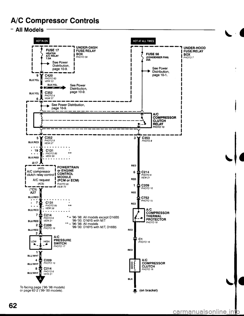
A/C Compressor Controls
- AllModels
cc5)M7
BLU/RED
?
\a
@
&cCOMPRESSORCLUTCHRELAYPHOfO 10
a
! ,acc, : POWERTRATN! arn.^-^,o..^, I or ENGINE
! ii i"i-iiii"v i.,ii.r | fi 3$18.
I A/C request ! (pCM or ECM)I (ACSJ a pHOrO a6L------J vtEw 70
REO
BEO
1
RED
BLU/FEO
2
BLU/FEO
ct31
:"1'!i'------;
Fi:rz, a ='e6-'s8: A|| moders except D1685vtEw 21 '99100: D16Y5 with l\illT'* = 96-'98: All models
ir'iio ," 99. 00: Dt6y5 wth t\4/t Dl6Bb
atcPRESSUREswtTcH
c752
c1
".,n""t 1(
".r-".rf, "tA% "
"."-:,fi tfr,]4.
v
To facing page ('96''98 models)or page 62'2 ( 99-'00 models).
-Yl
-t---------Jc353
c2'14
vtEW21
c209
A,/CCOMPRESSORCLUTCH
COMPRESSORTHERMALPROTECTOR
UNDER-HOODFUSE/RELAYBOXf-T-*-'.T'---l H53.',EPA?' i-l-------
i iflH* !F,?r",, i f6F"'.i:.",",
| tsBi":J;"#il ! a T| | oaoe 1o-9. ! I I See PowerL_J1_j:_-_j ! H Distriburion.e Y c42o i I
pase 1o-1.
***
f ifi"l'
^ see power ! |
62
!(on bracket)