Page 1108 of 2189
Steering Gearbox
Disassembly (cont'dl
22. Carelully pry the piston seal ring and O-ring off theprslon rack.
CAUTION| Be caletul not to damage the inside ofseal ring groove and piston edges when removing
the seal rin9,
Replace.
17-52
Valve Body Unii Disassembly
23. Eefore removing the valve housing, apply vinyl tapeto splines of the pinion shaft.
24. Separate the valve housing from the pinion shaft/
valve using a press.
VALVE HOUSING
Vinylt.pe
PINION SHAFT
Check the inner wall of the valve housing where theseal ring slides with your finger. lf there is a step inthe wall, the valve housing is worn. Replace thevalve housing.
NOTE:
There may be the sliding marks from the sealring on the wall of the valve housing. Replace
the valve housing only if the wall is stepped.When the valve housing is replaced, jnstall new
shim(s) on the bearing surface of the housing toadjust the thickness.
Check the inside of valve housingwhether the wall is stepped.
Page 1110 of 2189
Steering Gearbox
Disassembly (cont'd)
30. Bemove the valve oil seal and backup ring {'96 -'97
models) or wave washer ('98 -'00 models) from theoinion shaft.
NOTE:
. Inspect the ball bearing by rotating the outer race
slowly. lf there is any excessive play, replace thepinion shaft and sleeve as an assembly.
. The pinion shaft and sleeve are a precise fit; do
not intermix old and new pinion shafts and
steeves.
'98 - '(x) mod.lr:WAVE WASHERReplace.
31.Press the valve oil seal and roller bearing {'96 -,97
modelsl or bushing ('98 -'00 modelsl out of thevalve housing using a hydraulic press and specialtool shown below.
NOTE: Do not use a hammer; it will damage the
specialtool.
'96 - '97 modob:
PILOT COLLAR07GAF - PH70100
VAI.VE OIL SEALReplace.
BOI.I"ER BEARINGReplace.
PILOT COLLAR07GAF - PHtoroo
VALVE OII. SEALReplace.
BUSHINGBeplace.
BALL BEARING
'96 - '00 mod.b:
17-54
Page 1112 of 2189
Steering Gearbox
Reassembly (cont'd)
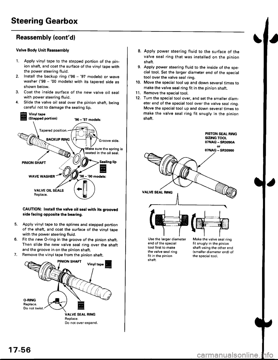
Valve Body Unit Reassembly
1. Apply vinyl tape to the stepped portion of the pin-
ion shaft, and coat the surface of the vinyl taoe with
the power steering fluid.
2. Install the backup ring ('96 -'97 models) or wavewasher ('98 -'00 models) with its tapered side as
shown below.
3. Coat the inside surface of the new valve oil sealwith power steering fluid.
4. Slide the valve oil seal over the pinion shaft, being
careful not to damage the sealing lip.
Vinyl t.po{Stepped ponion}
Tap6red position.
BACKUPGroove side.
sure the spring isseatod in the oil seal.
'98 - '00 mod.b:
CAUTION: InstEll ihe valve oil seal whh its groov.d
3ide tacing opposite tho boaring.
Apply vinyl tape to the splines and stepped portion
of the shaft, and coat the surface of the vinyl tapewith the power steering fluid.
Fit the new O-ring in the groove of the pinion shaft.Then slide the new valve seal ring over the shaft
and the groove in on the pinion shaft.
Remove the vinyl tape from the pinion shaft,
'96 - '97 models:
lip
7.
VALVE SEAL RIiIGReplace.Do not over-expand.
17-56
8. Apply power steering fluid to the surface of the
valve seal ring that was installed on the pinion
shaft.
9. Apply power steering fluid to the inside of the spe-cial tool. Set the larger diameter end of the specialtool over the valve seal ring.
10. Move the special tool up and down several times tomake the valve seal ring fit in the pinion shaft.11, Remove the soecial tool.
12. Turn the special tool over, and set the smaller diam-eter end of the special tool over the valve seal ring.Move the special tool up and down several times tomake the valve seal ring fit snugly in the pinion
shaft.
PISTON SEAL BINGSIZING TOOL07NAG - SR:togoAol07NAG - SR3|X)00
(g(m
Use the larger diameterend of the specialtool first to makethe valve seal ringfit in the pinionshaft.
Make the valve seal ringfit snugly in the pinionshaft using the other end(smaller diameter end) ofthe specialtool.
Page 1114 of 2189
Steering Gearbox
Reassembly (cont'd)
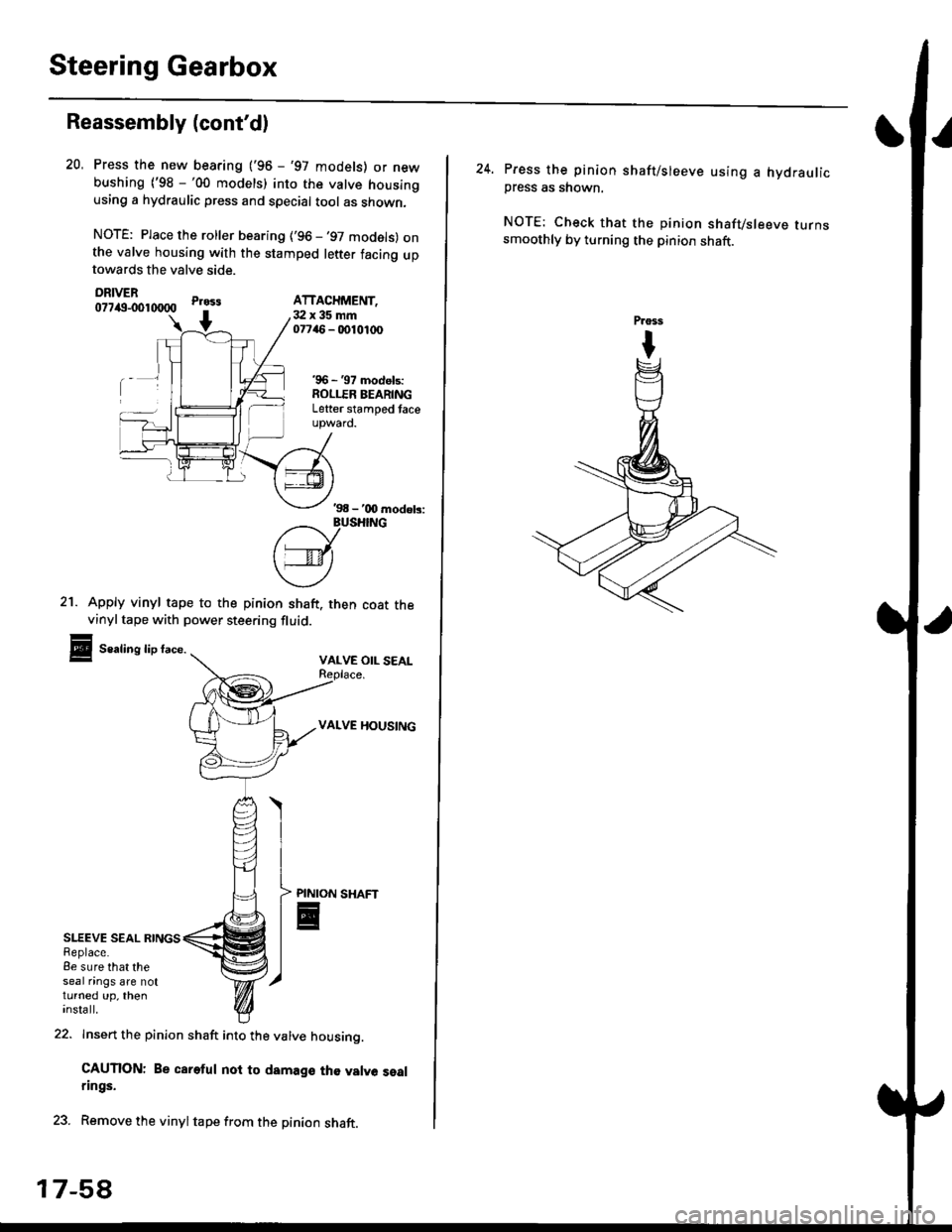
SLEEVE SEAL RINGSReplace.8e sure that theseal nngs are notturned up, theninsta ll.
21. Apply vinyl tape to the pinion shaft. then coat thevinyltape with power steering fluid.
Sealing lip face.VALVE OIL SEAL
VALVE HOUSING
Press the new bearing ('96 - '97 models) or newbushing ('98 -'00 models) into the valve housingusing a hydraulic press and special tool as shown,
NOTE: Place the roller bearing ('96 -'97 models) onthe valve housing with the stamped letter facing uptowards the valve side.
DRIVER077itg-001tXlOO
22. Insert the pinion shaft into the valve housino.
CAUTION: Be careful noi to damage th€ valve sealrings.
23. Remove the vinyltape from the pinion shaft.
20.
Pr033
+3:Ix35mm07746 - 0010,t(x)
'96 - '97 models:ROLLER BEARINGLetter stamped taceupward.
ATTACHMENT,
'98 - '00 modob:
?/_vusHrNG
['---v-lt
\4)
PINION
E
17-5A
24. Press the pinion shaft/sleeve using a hydraulicpress as shown.
NOTE: Check that the pinion shafvsleeve turnssmoothly by turning the pinion shaft.
Page 1116 of 2189
Steering Gearbox
Reassembly {cont'd)
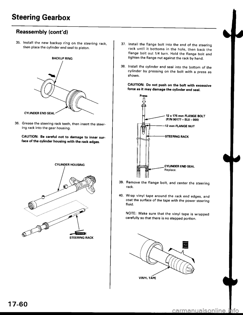
35. Install the new backup ring on the steering rack,then place the cylinder end seal to piston.
Grease the steering rack teeth, then Insen the steer-ing .ack into the gear housing.
CAUTION: Be careful not to damage to inner sur-face of the cylindsr housing with the rack edges.
36.
BACKUP RING
17-60
37. Install the flange bolt into the end of the steerinorack until it bottoms in the hole, then back thlflange bolt out 1/4 turn. Hold the flange bolt andtighten the flange nut against the rack by hand.
38. Install the cylinder end seal into the bottom of thecylinder by pressing on the bolt with a press asshown.
CAUTION: Do not push on the boh with excessiveforce as it may damage tho cylinder end seal.
12 x 175 mm FLANGE BOLT{P/N 90177 - SLo - 000}
12 mm FLANGE NUT
?qRemove the flange bolt. and center the steeringrack.
Wrap vinyl tape around the rack end edges. andcoat the surface of the tape with the power steeringfluid.
NOTE: Make sure that the vinyl tape rs wrappedcarefully so that there is no stepped portion.
Preas
Page 1117 of 2189
)
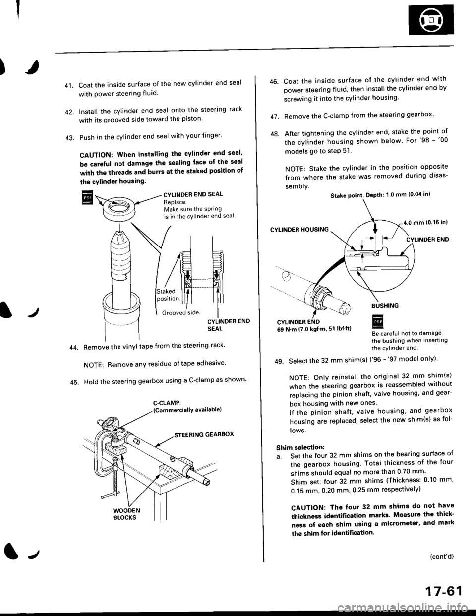
41.Coat the inside surface of the new cylinder end seal
with power steering fluid.
Install the cylinder end seal onto the steering rack
with its grooved side toward the piston'
Push in the cylinder end seal with your finger'
CAUTION: When installing the cylinder end sesl'
be carelul not damage the sealing face ot the seal
with the threads and burrs at the staked position oI
the cylinder housing.
trCYLINDES END SEAL
Replace.Make sure the sPring
is in the cylincler end seal
CYLINDER END
SEAL
Remove the vinyl tape from the steering rack'
NOTE: Remove any residue oftape adhesive
Hold the steering gearbox using a C-clamp as shown'
GEARBOX
C-CLAMP:
l-,
46.
47.
Coat the inside surface of the cylinder end with
power steering fluid, then installthe cylinder end by
screwing it into the cylinder housang.
Remove the C-clamp from the steering gearbox'
After tightening the cylinder end' stake the point of
the cylinder housing shown below For'98 -'00
models go to step 51.
NOTE: Stake the cylinder in the position opposite
from where the stake was removed during disas-
semoly.
Be careful not to damage
the bushing when inserting
the cylinder end.
49. Select the 32 mm shim(s) ('96 -'97 model only)'
NOTE: Only reinstall the original 32 mm shim(s)
when the steering gearbox is reassembled without
replacing the pinion shatt, valve housing, and gear
box housing with new ones.
lf the pinion shaft, valve housing, and gearbox
housing are replaced, select the new shim{s) as fol-
lows.
Shim selection:
a. Set the four 32 mm shims on the bearing surface of
the gearbox housing. Total thickness of the four
shims should equal no more than 0 70 mm'
Shim set: four 32 mm shims (Thickness: 010 mm'
0.15 mm, 0.20 mm, 0.25 mm respectivelyl
CAUTION: Th€ four 32 mm shims do not have
thickness identification marks Measure the thick-
ness of each shim using a micrometsr, and mark
the shim lor identification.
(cont'd)
17-61
Stake point. Depth: 1 0 mm (0.04 in)
Page 1118 of 2189
Steering Gearbox
Reassembly (cont'd)
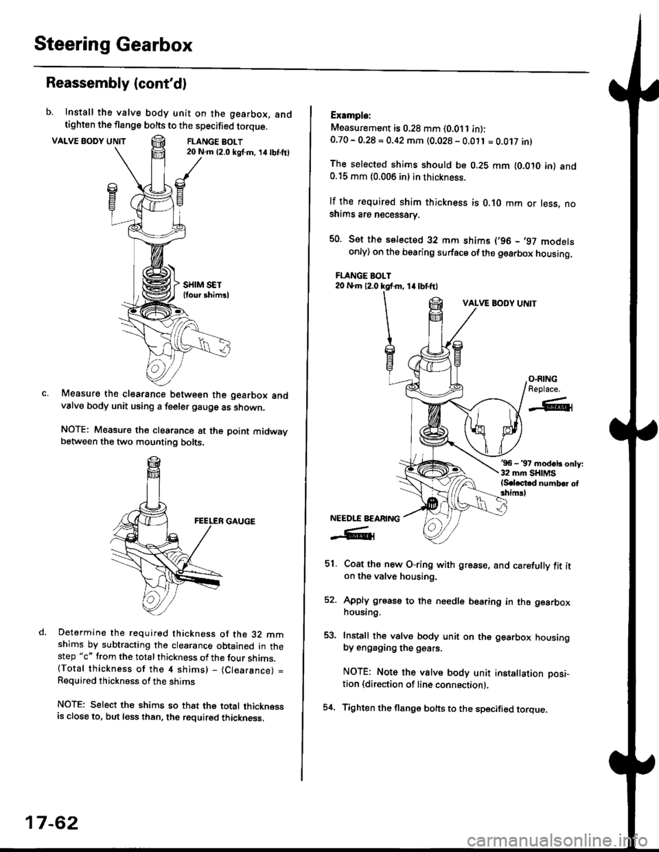
b. Install the valve body unit on the gearbox, andtighten the flange bolts to the specified torque.
VALVE BODY UNTTFLANGE BOLT20 N.m {2.0 ksl.m, 14lbI.ftl
Measure the clearance between the gearbox andvalve body unit using a feeler gauge as shown.
NOTE: Measure the clearance at the point midwaybetween the two mounting bolts.
Determine the required thickness of the 32 mmshims by subtracting the clearance obtained in thestep "c" from the total thickness of the four shims.(Total thickness of the 4 shims) - (Clearance) =
Required thickness of the shims
NOTE: Select the shims so that the total thicknessis close to. but less than, the required thickness,
17-62
54.
Example:
Measurement is 0.28 mm (0.011 in):0.70 - O.28 = 0.42 mm (0.028 - 0.011 = O.Ot7 inl
The selected shims should be 0.28 mm lO.OtO in) and0.15 mm {0.006 in} in thickness.
lf the r€quired shim thickness is 0.10 mm or less, noshims are necessarv.
50. Sot the selected 32 mm shims (,96 - ,97 modelsonly) on the bearing surface ofthe gearbox housing.
FLANGE BOLT20 N.m 12.0 ksf.m, 1l lbtftl
VALVE BODY UNIT
'96 - 37 modsl3 only:32 mm SHIMS{S.loctod numb.r of3him!l
Coat ths new O-ring with grease, and carefully fit iton the valve housing.
Apply grease to the needle bearing in the gearboxhousing.
Install the valve body unit on the gearbox housingby engaging the g€ars.
NOTE: Note the valve body unit installation posi-
tion (direction of line connection).
Tighten the flange bolts to the specified torque.
O-RINGReplace.
-A-l
NEEDLE BEARING
-R1
51.
EA
Page 1120 of 2189
Steering Gearbox
Reassembly (cont'dl
64. Apply grease to the circumference of the rack endhousing.
RACK END GROOVE
=^.#-q!:s!!H
SILICONE GREASE
Apply a light coat of silicone grease to the bootgrooves on the rack ends.
lnstall the boots in the rack end with the tie-rodclips.
NOTE: Install the boots with the rack in the straightahead position (right and left tie-rods are equal inlength).
66.
RACK END
NOTE: Wipe the grease offthe thread section.
17-64
TIE.ROD CLIP
67. Adjust the air hose fitting position of the boots bvturning it as shown below.
LEFT BOOT(Viewed from theleft side)
RIGHT BOOT{Viewed from theright side)
AIR HOSE FITTING
Install new boot bands on the boot, and bend bothsets of locking tabs.
CAUTION: Stlke ths band locking tabs firmly.
Lightly tap on the doubled-over portions to reducetheir height.
Slide the rack right and left to be certain that theboots are not deformed or twisted.