1997 HONDA CIVIC under dash
[x] Cancel search: under dashPage 760 of 2189

Electrical Troubleshooting ('99 - 00 Models)
Troubleshooting Flowchart - Lock-up Control Solenoid Valve B
NOTE| Record allfreeze data before you troubleshoot.
Possibla Cause
. Oisconnected lock-uD controlsolenoid velve A/B assemblyconnector. Short or open in lock-up controlsolenoid valv€ B wire. Faulty lock-up control solenoidvalve B' Open in VB SOL wirercM CONNECTORS
To page 14-83
' OBD ll Scan Tool indic.tes CodeP1758.. Self-diagnosis E indicatorlight blinks twice.
Chack for a Short to Power:1. Turn the ignition switch OFF.2. Disconnect the I (25P) and D(16P) connectors from thePCM.3. lurn the ignition switch ON (ll).4. Measure the voltage betweenthe D3 and 820 ot 822 tetmi-nals,
Repair short to power in the wirebetween the D3 terminal and thelock-up contlol solenoid valve B.
Measure Lock-up Control Sole-noid Vdlve I R8i3tance:1. Turn the ignition switch OFF.2, Measure the resistancebetween the D3 and 820 or822 terminals.
ls the resistance 12 - 25 O?
Measure VB SOL Voltago:1. Turn the ignition switch ON lll).2. Measure the voltage betweenthe D5 and 820 or 822 termi-nals.
Check for blown No. 15 {7.5 Alfus€ in the under-dash luse/releybox. It the fuse is OK, repair openin the wir6 between th6 DS terminal and the under-dash fuse/rebyoox,
ls there battery voltage?
Chock for loose te.minal fit in thePCM connectors. It necessary,substitute a known-good PCMend recheck.
B t2sP) ll D t15P)
Wire side ol female terminals
I {2sPt ll D (16Pt
B (25P1 D t16Pt
\
14-82
Page 769 of 2189

Troubleshooting Flowchart - Shift ControtSolenoid Valve B
NOTE: Record all freeze data before you troubleshoot.
Possiblg Cause
. Disconnectgd ihilt control
solenoid valve A/B conneciotr Short or oDen in shift conlrol
3olgnoid vrlve B wito. Faulty 3hift control solenoid
velve B. Op€n in VB SOL wirercM CONNECTORS
LGlIBRN/BLKI LG2IBRN/BLK)
Wire side of {emale terminals
LGi (BRi|/BLKILG2 IBRN/8LK)
To page 14-92
(cont'd)
14-91
. OBD ll Scan Tool indic.l6 Code
P0758.' Self-diagnosb El indicator light
blinks eighl tim6.
Check tor a Shortto Power:
1. Turn the ignition switch OFF
2. Disconnect the B (25P) and D(16P) connectors from the
PCM.3. Turn the ignition switch ON (lli.
4. Measure the voltage between
the D2 and 820 or 822 termi
nals,
Repaft 3hon to Powor in the wir€
b€tirvoon the D2 termin.l and the
3hift control solenoid valve B.
M€asure Shift Control SolenoidValve B R6isttnce:1. Turn the ignition switch OFF
2. Measure the resistance
between the D2 and 820 or
822 terminals.
ls the resistance 12 - 25 O?
Me.sure VB SOL Vohage:1. Turn the ignition switch ON (ll).
2. Measure the voltage betweenthe D5 and 820 or 822 termi'
nars.
Check lol blown No 15 {7.5 Al
fuse in the under-d.sh luae/rolav
box. ll the fuse is OK, repair open
in ihe wire between tho D5 ter-
minal and the under'dash fus€/relav box.
ls there battery voltage?
Check for loo3e terminal fit in the
PCM connectols. lf necossarY,
substitute a known_good PCM
and rocheck,
B (25Pt - I lD {16P)
B {25P1 D (t6Pl
Page 873 of 2189

Description
The Continuously Variable Transmission (CVT) is an electronically controlled automatic transmission with drive and driv
en Oullevs, and a steel belt. The CVT provides non stage speeds forward and one reverse. The entire unit is positioned in
line with the engine.
Transmission
Around the outside of the flywheel is a ring gear which meshes with the starter pinion when the engine is being staned.
The transmission has four parallel shafts: the input shaft, the drive pulley shaft. the driven pulley shaft, and the secondary
gear shaft. The input shaft is in line with the engine crankshaft. The drive pulley shaft and the driven pulley shaft consist of
movable and fixed face pulleys. Both pulleys are linked by the steel belt.
The input shaft includes the sun gear. The drive pulley shaft includes the forward clutch which mounts the carrier assem-
bly on the forward clutch drum. The carrier assembly includes the pinion gears which mesh with the sun gear and the ring
gear. The ring gear has a hub-mounted reverse brake disc.
The driven pulley shaft includes the start clutch and the secondary drive gear which is integral with the park gear' The sec-
ondary gear shaft is positioned between the secondary drive gear and the final driven gear. The secondary gear shaft
includes the secondary driven gear which serves to change the rotation direction. because the drive pulley shaft and the
driven oullev shaft rotate the same direction. When certain combinations of planetary gears in the transmission are
engaged by the clutches and the reverse brake, power is transmitted from the drive pulley shaft to the driven pulley shaft
to provide E, E, E, and El.
Electronic Control'96 - 98 Models:
The electronic control system consists of the Transmission Control Module (TCM), sensors, three linear solenoids, and a
inhibitor solenoid. Shifting is electronically controlled under all conditions'
The TCM is located below the dashboard, behind the kick panel on the driver's side.'99 - 00 Models:
The electronic control svstem consists of a Powertrain Control Module (PCM), sensors, three linear solenoids and an
inhibitor solenoid. Shifting is electronically controlled under all conditions. A Grade Logic Control System to control shift-
ing in E position while the vehicle is ascending or descending a slope.
The PCM is located below the dashboard, under the kick panel on the passenger's side.
Hydraulic Control
The lower valve body assembly includes the main valve body, the Pressure Low (PL) reguiator valve body, the shift valve
body, the start clutch control valve body, and the secondary valve body. They are positioned on the lower part of the
transmission housing.
The main valve body contains the Pressure High (PH) control valve, the lubrication valve, and the pitot regulator valve.
The secondary valve body contains the PH regulator valve, the clutch reducing valve, the start clutch valve accumulator,
and the shift inhibitor valve. The PL regulator valve body contains the PL regulator valve and the PH-PL control valve
which is ioined to the PH,PL control linear solenoid. The inhibitor solenoid valve is bolted on the PL regulator valve body.
The shift valve body contains the shift valve and the shift control valve. which is joined to the shift control linear solenoid.
The start clutch control valve body contains the start clutch control valve, which is joined to the start clutch control linear
solenoid. The linear solenoids and the inhibitor solenoid are controlled by the TCM or PCM. The manual valve body which
contains the manual valve and the reverse inhibitor valve, is bolted on the intermediate housing.
The ATF pump assembly is located on the transmission housing, and is linked with the input shaft by the sprockets and
the sprocket chain. The pulleys and the clutch receive fluid from their respective feed pipes, and the reverse brake receives
fluid from internal hydraulic circuit.
Shift Control Mechanism
Input from various sensors located throughout the vehicle determines which linear solenoid the TCM or PCM will activate.
Activating the shift control linear solenoid changes the shift control valve pressure, causing the shift valve to move. This
pressurizes the drive pulley pressure to the drive pulley and the driven pulley pressure to the driven pulley and changes
their effective pulley ratio. Activating the start clutch control linear solenoid moves the start clutch control valve. The start
clutch control valve uncovers the port, providing pressure to the start clutch to engage it(cont'd)
14-195
,!
Page 881 of 2189

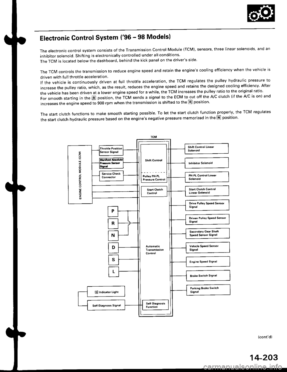
Electronic Control System ('96 - 98 Modelsl
The electronic control system consists of the Transmission control Module (TcM), sensors, three linear solenoids, and an
inhibitor solenoid. Shifting is electronically controlled under all conditions
The TCIM is located below the dashboard, behind the kick panel on the driver's side'
The TcN4 controls the transmission to reduce engine speed and retain the engine's cooling efficiency when the vehicle is
driven with Iull throttle acceleration
lf the vehicle is continuously driven at full throttle acceleration, the TCM regulates the pulley hydraulic pressure to
increase the pulley ratio, which, as the result. reduces the engine speed and retains the designed cooling efficiency After
the vehicle has been driven at a lower engine speed for a while, the TCM increases the pulley ratio to the original ratio.
For smooth starting in the E position, the TcM sends a signal to the EcM to cut off the rvc clutch {if the A!/c is on) and
increases the engine speed to 900 rpm when the transmission is shifted to the E position'
The start clutch functions to make smooth starting possible. To let the start clutch function properly. the TCM regulates
the start clutch hydraulic pressure based on the entine's negative pressure memorized in the E position'
:
:
z
z
z
S*ond.ry G..r Sh:ft
(cont'd)
14-203
Page 883 of 2189

Electronic Gontrol System ('99 - 00 Modelsl
The electronic controt system conststs of a Powertrain control Module (PCM). sensors, three linear solenoids and an
inhibitor solenoid. shifting is electronically controlled under all conditions A Grade Logic control system to control shift-
ing in E position while the vehicle is ascending or descending a slope'
fn"pCVirlocatedbelowthedashboard,underthekickpanelonthepassenger'sside'
The pCM controls the transmassion to reduce engine speed and retain the engine's cooling efficiency when the vehicle is
driven with full throftle acceleration
lf the vehicle is continuously driven at lull throttle acceleration, the PCM regulates the pulley hydraulic pressure to
increase the pulley ratio which. as the result, reduces the engine speed and retains the designed cooling efficiency After
the vehicle has been driven at a lower engine speed for a while, the PCM increases the pulley ratio to the original ratio'
i"i ".nl",rr starting in the E position, the PcM cuts off the ,Vc clutch (if the A/c is on) and increases the engine speed to
900 rpm when the transmission is shifted to the E position'
The start clutch functions to make smooth starting possible. To let the start clutch function properly, the PcM regulates
the start clutch hydraulic pressure based on the engine's negative pressure memorized in the E position'
FCM
s*o.d.ry G..t Sh.h
(cont'd)
14-205
Page 912 of 2189

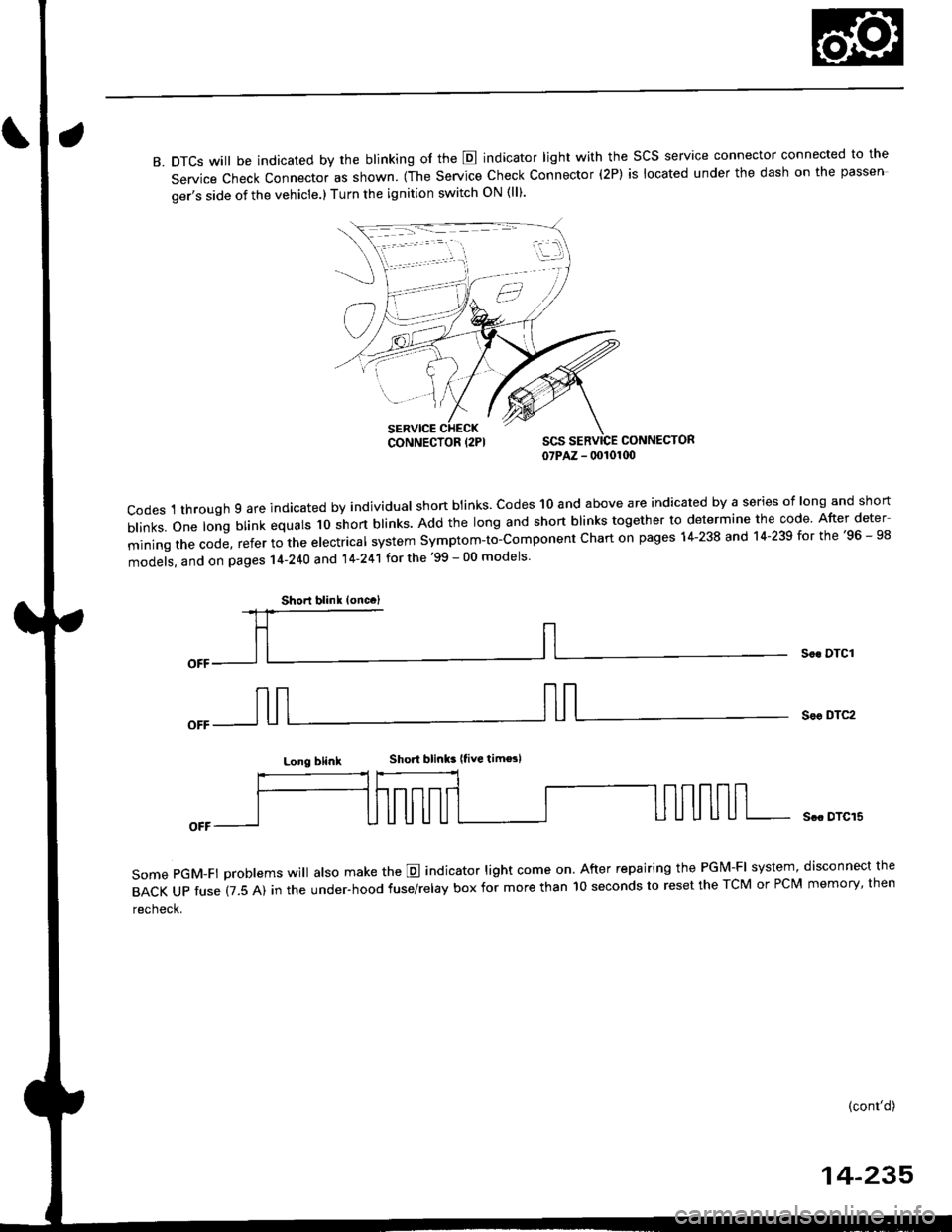
B. DTCS will be indicated by the blinking of the E indicator light with the SCS service connector connected to the
Service Check Connector as shown. (The Service Check Connector (2P) is located under the dash on the passen
ger's side of the vehicle.) Turn the ignition switch ON (ll).
CONNECTOR07PAZ - 00101(x)
codes 1 through 9 are indicated by individual shon btinks. codes 10 and above are indicated by a series of long and short
b|inks.one|ongblinkequa|sloshortb|inks.Addthe|ongandshortb|inkstogethertodeterminethecode.Afterdeter
miningthecode,refertothee|ectrica|systemsymptom-to-componentchartonpagesl4-238and14.239forthe,96_98
models, and on pages 14-240 and 14'241 for the '99 - 00 models
Soc DTCI
Sor DTC2
Long blinkShort blinks |tive tim€sl
some pGM-Ft problems wi
atso make the E indicator light come on. After repairing the PGM-FI system, disconnect the
BACKUPfuse(7.5A)intheUnder.hoodfuse/re|ayboxformorethanl0secondstoresettheTcMorPcMmemory,then
recheck.
Scc DTCI5
(cont'd)
14-235
iii:j
,,,/
CONNECTOR {2PI
Shorl blink (oncc)
Page 940 of 2189

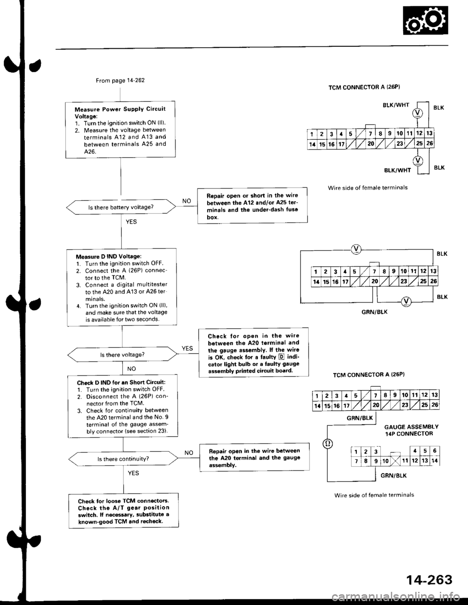
Ftom page 14 262
ls there battery voltage?
Measure Powet SUPPIY Ci.cuit
Voltage:1. Turnthe ignition switch ON (ll)
2. Measure the voltage between
terminals A12 and A13 and
between terminals A25 and
426.
Repair open or short in the wire
between the A'12 andlor Ms ler-
minrls and the under-dash fuse
DOX,
Measure D IND Voltage:1. Turn the ignition switch OFF
2. connect the A (26P) connec
tor to the TcM.
3. Connect a digkal multitester
to the A20 and A'13 or A26 ter
minals.4. Turn the ignition switch ON (ll),
and make sure that the voltage
is available for two seconds.
Check tor opon in the wire
between the A20 l6rminal and
the gaug€ assembly. It the wite
is OK, check tor a faultY ipl indi-
calor light bulb or a faulty gauge
assembly prir ed circuit boatd.
Check D INO for an Shott Circuit:1. Turn the ignition switch OFF
2. Disconnect the A (26P) con-
nector from the TCM.
3. Check for continuity between
the A20 terminal and the No. I
terminal of the gauge assem-bly connector (see section 23).
Bepair open in the wire between
the A20 terminal and the gauge
assembly.
Check tor looso TCM connecto.s.
Check the A/T ge.r Positionswitch. lf nec6ssary, substitute a
known-good TCM and r€check
BLK/WHTI
r
2a710111213
14t5161720232526
BLK/WHT
A
II
TCM CONNECTOR A I26P)
Wire side of female terminals
TCM CONNECTOR A (25P}
BLK
BLK
GRN/BLK
12a58910111213
1l15161720232526
o
GRN/BLK
GAUGE ASSEMBLY14P CONNECTOR
a5
78910111214
GRN/BLK
Wire side of female terminals
Page 948 of 2189

JTroubleshooting Flowchart - Shift Control Linear Solenoid
NOTE: Record all freeze data before you troubleshoot
Possiblc Cause
. Disconn€cted solenoid harnos3
connectol. Short or oDen in shilt controllinetr solonoid wiro. Faulty shift control linear sole_
noid. Op€n in VB SOL wite. ODen in PG'l and PG2 wires or
poor ground {G10'l)
f,
wire side ot female terminals
LG1 IBRN/BLKILG2IBRN/BLK)
{cont'd)
14-271
PCM CONNECTORS
B(25P) - Dll6P)
.OBD ll Scan Tool indicatos
Code P1870.. Solf-diagnosis E indic.lor light
indic.t€s Code 30.
M6a3ure VB SOL voltage:1. Turn the ignition switch OFF.
2. Disconnect the B 125P) and D(16P) connectors from the
PCM,3. Turn the ignition switch ON (ll).
4. Measure the voltage between
the D5 and 820 or 822 terminals.
Repair open or shod in the wire
between the D5 terminal and the
under-dash tuso/telay box.
Check the Ground Circuitl1. Turn the ignition switch OFF.2. Check lor continuity between
the terminafs 82 and 822 and
between terminals 810 and
820.
Repair open in the wi.e betwoen
the termin.ls 82, B10, B20, and
822 and G101. Repair Poolground (G101).
LG1 IBRN/BLKI
PCM CONNECTOR B PsPI
PG,I IBLK)
10 page 14-272
a