Page 1180 of 2189
Rear Brake Disc
Disc Runout Inspection
1.Loosen the front wheel nuts slightly, then raise thevehicle, and suppon it on safety stands. Removethe front wheels.
Remove the brake pads (see page 19-24).
Inspect the disc surface for damage and cracks.Clean the disc thoaoughly, and remove a
rust.
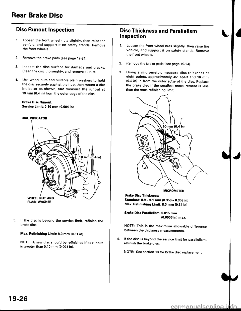
Use wheel nuts and suitable plain washers to holdthe disc securely against the hub. then mount a dialindicator as shown. and measure the runout at10 mm (0.4 in) from the outer edge of the disc.
Brake Disc Runout:
Service Limit:0.10 mm {0.00,t in)
5. lf the disc is beyond the service limit, refinish thebrake disc,
Max. Retinishing Limit: 8.0 mm {0.31 in)
NOTE: A new disc should be refinished if its runoutis greater than 0.10 mm (0.004 in).
19-26
Disc Thickness and Parallelism
Inspection
1. Loosen the front wheel nuts slightly, then raise thevehicle, and support it on safety stands. Removethe front wh6els.
2. Remove the brake pads (see page j9-24).
3. Using a micrometer. measure disc thickness aterght points, approximately 45" apart and 1o mm{0.4 in) in from the outer edge of the disc. Replacethe brake disc if the smallest measurement is lessthan the max. refinishing limit.
Brake Disc Thickness:
Standard: 8.9 - 9.1 mm (0.350 - 0.358 in)Max. Rsfinishing Limit: 8.0 mm {0.31 in}
Brake Disc Parallelirm: 0.015 mm(0.0006 inl msx.
NOTE; This is the maximum allowable differencebetween the thickness measurements.
4. lf the disc is beyond the service limit for Darallelism.refinish the brake disc.
NOTE; See section 18 for brake disc replacement.
Page 1198 of 2189
Component Locations
ta
SERVICE CHECK CONNECTOR {2PIBIGHT.REAR WHEELSENSOR CONNECTORMOOULATOR UNITABS CONTROL UNIT
RIGHT-REAR WHEEL SENSOR
LEFT.R€AR WHEELSENSOR CONNECTOR
J
UNDER.DASH FUSE/RELAY 8OX
LEFT.FRONT WHEEL SENSOR
ABS +B (20 A) FUSE
UNDER.HOOD FUSE/RELAY BOX
lcl lilo Al FUSE
ABS INDICATOR LIGHT
UNOEF.DASI{ FUSE/RELAY BOX
HORN/STOP I15 A) FUSE
UNDER.HOOO ABS FUSE/RELAY BOX
PUMP MOTOR {'O A} FUSE
PUMP MOTOR BELAY
E
o
METEB I7.5 AI FUSE
0
0
0
00000 n
00000 u
BR DEF RLY 17,5 A) FUSE
t
MTR CHECK (7.5 AI FUSE
19-45
Page 1206 of 2189
e\
t
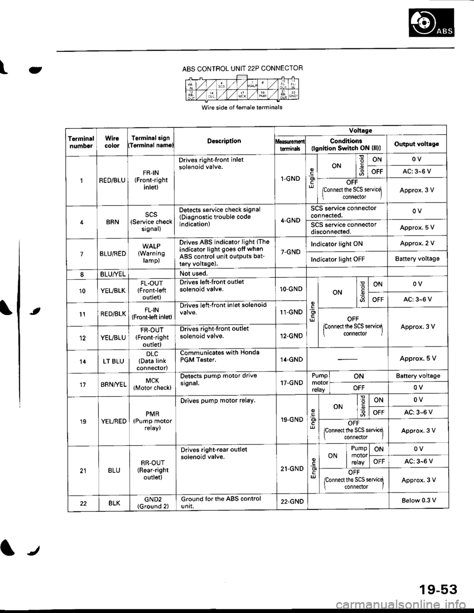
ABS CONTROL UNIT 22P CONNECTOR
Wire side of female terminals
TerminalnumbelWirocororTerminalsignDe3cription
Volt.ge
ConditionE(lgnition Switch ON (ll)lOutput voltagolTqrminal namslterminils
RED/BLUFR-IN{Front-rightinlet)
Drives right-front inletsolenoid valve.
I-GNDriJ
ON-9ONOV
OFFAC: 3-6 V
OFF
/Connect the SCS servicq
connector IApprox. 3 V
BRNscs(Service checksignal)
Detects service check signal
{Diagnostic trouble codeindication)4-GND
SCS service connectorconnected.OV
SCS service connectordisconneded.Appro)(. 5 V
7BLU/RED(Warning
ramp)
Drives ABS indicator light (The
indicator light go€s off when
ABS control unit outputs bat-
tery volta9e),
7-GND
Indicator light ONApprox, 2 V
Indicator light OFFBattery voltage
8BLU/YELNot used.
10YEUBLKFL.OUT{Front-leftoutlet)
Drives left-front outletsolenoid valve.10-GNOON
ONOV
OFFAC:3-6 V
11RED/BLKFLIN{Front-l€ft inlet)
Drives left-front inlet solenoid11-GNDOFF
lconnect the SCS servicq
connector IApprox. 3 V
YEUBLU
FR.OUT(Front-right
outlet)
Drives right-front outlet
solenoid valve.12-GNO
l4LT BLUDLC(Data linkconnector)
Communicates withPGM Tester.Honda14.GNDApprox. 5 V
17BRNA/ELMCK
lMotor check)
Detects pump motor drivesrgnal.17.GNDPumpmotorreray
ONBattery voltage
OFFOV
19YELREDPMR(Pump motorreray,
Drives pump motor relay.
19-GND
ONONOV
OFFAC: 3-6 V
OFFponnect the SCS sewicq
connedor lApprox. 3 V
BLURR-OUT(Rear-right
outletl
Drives right-rear outlel
solenoid valve.
21-GNDuJ
ON
Pumpmotorrelay
ONOV
OFFAC: 3-6 V
OFF
lconnect the SCS servicq
connedor )Approx. 3 V
22BLKGND2(Ground 2)Ground for the ABS controluntt.22-GNDBelow 0.3 v
19-53
Page 1209 of 2189
Diagnostic Trouble Code (DTCI
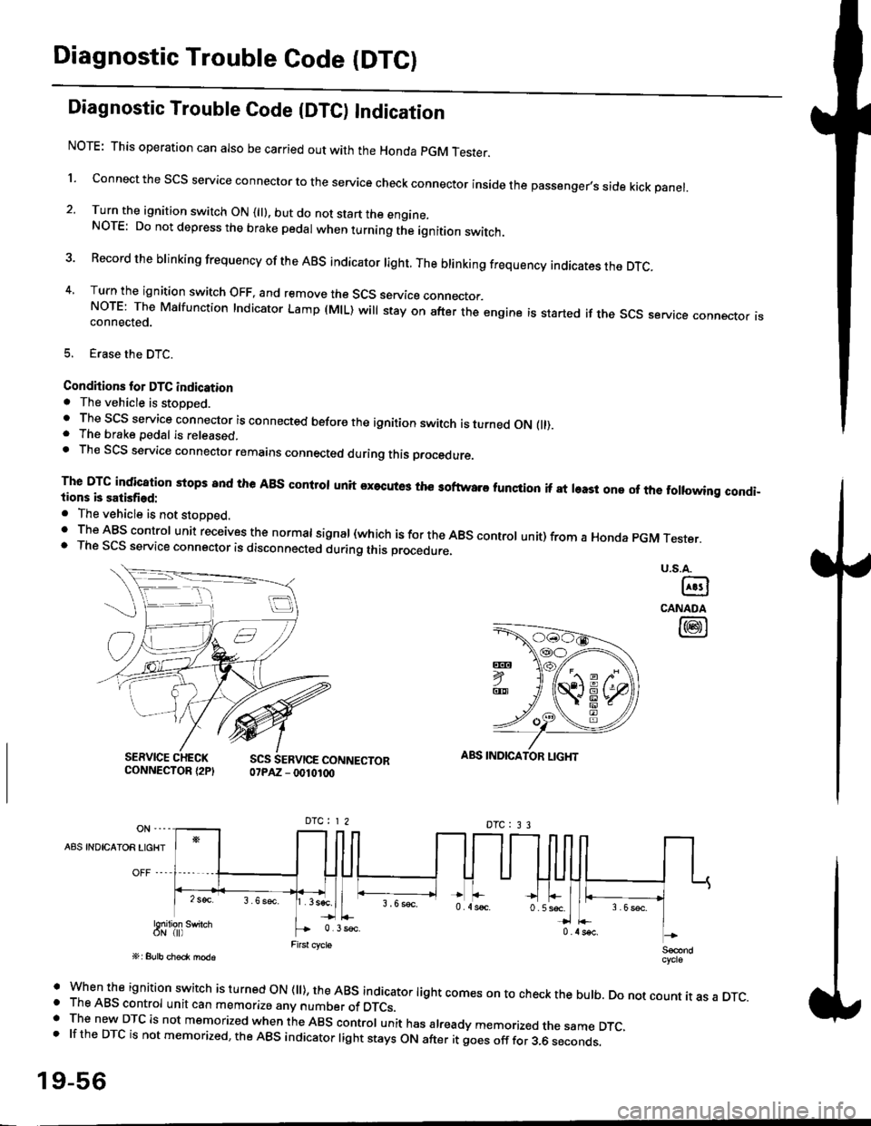
Diagnostic Trouble Code {DTC) Indication
NOTE: This operation can also be carried out with the Honda pGM Tesrer.
l connect the scs service connector to the service check connector inside the passenger,s side kick panel.
2. Turn the ignition switch ON (||). but do not start the engine.NOTE: Do not depress the brake pedal when turning the ignition switch.
3 Record the brinking frequency of the ABS indicator right. The brinking frequency indicates the DTc.
4, Turn the ignition switch OFF, and remove the SCS service connector.NorE: The Mslfunction Indicator Lamp (MlL) will stay on after the engine is started if the scs service connector isconnected.
5. Erase the DTC.
Condhions for DTC indication. The vehicle is stoDDed.. The SCS service connector is connected before the ignition switch is turned ON fll).. The brake pedal is released.. Th€ SCS service connector remains connected during this procedure
The DTG indication stops 8nd the ABs conltol unit executes the softwaro tunqtion if at least one of the following condi-tions b satisfied:
o The vehicle is not stoDoed.' The ABS control unit receives the normat signal (which is for the ABS controt unit) from a Honda pGM Tester.. The SCS service connector is disconnected during this procedu.e,
u.s.A.
@
CANADA
@
SERVICE CHECKCONNECTOR {2PISCS SERVICE CONNECTOR07PAZ - 0010100
ABS INDICATOR LIGHT
DTC : 3 3
A8S INDICAIOR LIGHT
Snilion swirch
' when the ignition switch is turned oN (ll), the ABs indicator light comes on to check the bulb. Do not count it as a DTc.o The ABS control unit can memorize any number of DTCs.. The new DTC is not memorized when the ABS control unit has already memorized the same DTC,.lftheDTCisnotmemorized,theABSindicatorlightstaysONafteritgoesofffor3.6seconds.
19-56
Page 1210 of 2189
LJDTG Erasure
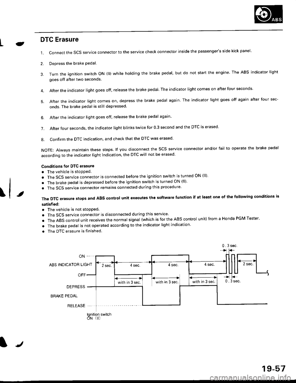
1.
2.
Connect the SCS service connector to the service check connector inside the passenger's side kick panel.
Depress the brake pedal.
Turn the ignition switch oN (ll) while holding the brake pedal, but do not start the engine. The ABS indicator light
goes off after two seconds.
After the indicator light goes off, release the brake pedal The indicator lightcomeson after four seconds
After the indicator light comes on, depress the brake pedal again. The indicator light goes off again after four sec-
onds. The brake pedal is still depressed.
4.
5.
\t
6. After the jndicator light goes off, release the brake pedal again'
7. After four seconds, the indicator light blinks twice for 0 3 second and the DTC is erased
8. Confirm the DTC indication, and check that the DTC was erased
NOTE: Always maintain these steps. lf you disconnect the scs service connector and/or fail to operate the brake pedal
according to the indicator light indication, the DTC will not be erased
Conditions for DTC erasure
o The vehicle is stopped.
. The SCS service connector is connected before the ignition switch is turned ON {ll)
. The brake pedal is depressed before the ignition switch is turned ON (ll)'
. The SCS service connector remains connected during this procedure
The DTC erasure stops and ABS control unit executes the software lunction it at least one ot the following conditions is
satisfied:
o The vehicle is not stopped.
. The SCS service connector is disconnected during this servace'
.TheABscontro|unitreceivesthenormaIsigna|(whichisfortheAEscontro|unit)fromaHondaPGMTester'
. The brake pedal is not operated according to the indicator light indication
. The DTC erasure is finished
ABS INDICATOR LIGHT
OFF
DEPRESS
BRAKE PEDAL
RELEASE
0.3sec
lqnition switchoN (I)
J
19-57
Page 1219 of 2189
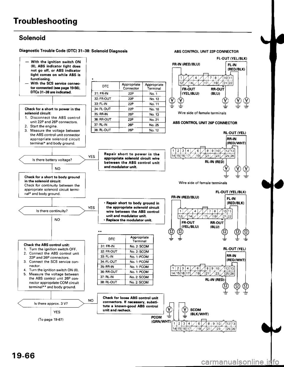
Troubleshooting
Solenoid
Diagnostic Trouble Code {DTC} 31-38: Solenoid Diagnosis
YES
ABS CONTROL UNIT 22P CONNECTOR
Wire side of female terminals
ABS CONTROL UNIT 26P CONNECTOR
FL.OUT (YEL/ALK)- With the ignition switch ON(lll, ABS indicator light doesnol go oft. or ABS indic.to.light comes on while ABS i3functioning.- With the SCS servico connec-tor connected ls€. pag€ 19-561,DTCa 31-38 are indicstod.
Check for a short lo powor in thosol6noid circuitl1. Disconnect the ABS controlunit 22P and 26P connectors.2. Sta rt the engine.3. Measure the voltage betweenthe ABS control unit connectorappropriate solenoid circuitterminal* and body ground.
Ropri. short to powor in thcappropriate solanoid ci.cuit wirobotw6.n ths ABS cont.ol unitand modulrtor unit.
ls there battery voltage?
Check for a short to body groundin the 3olenoid circuit:Check tor continuity between theappropriate solenoid circuit termi-nal* and body ground.
. Repair short to body ground inlhe .ppropriato solonoid circuitwire betwoan th6 ABS controlunit and modllato. unit.. Replaco the modul.tor unit.
Check th€ ABS control unit:'1. Turn the ignition switch OFF.2. Connect the ABS control unit22P and 26P connectors.3. Connect the SCS service con-
4. Turn the ignition switch ON {ll}.5. Measure the voltage betweenthe ABS control unit 26P con-nector appropriate CONI circuitterminal++ and body ground.
Check for loos€ ABS control unhconnectora. It naceslrry, aub3ti-tutc . known-good ABS controlunit tnd recheck.
ls there approx. 3 V?
DTCAppropriateConnectorAppropriateTerminal
31: FRJN22PNo. 1
32: FR-OUT22PNo.12
33i FL'IN22PNo. 11
34: FL OUT22PNo.10
3s: RRIN26PNo.13
36: RR-OUT22PNo. 21
37: RLIN26PNo.25
38: RL-OUT26PNo.12RL.OUT IYEL}
Wire side of female terminals
DTCAppropriateTerminal
31: FR-lNNo. 2: SCOM
32: FR-OUTNo. 2: SCOM
33i FLINNo. 1: rcOM
34: FL-OUTNo. l: PCOM
35: RR{NNo.1:PCOM
36: RR-OUTNo. 1: rcOM
37rRL'lNNo. 2: SCOM
38: RL-OUTNo. 2: SCOM
RL.OUT (YEL}
19-66
(To page 19-671
Page 1619 of 2189
A/T Gear Position Indicator
Component Location lndex
sRS components are located in this area. Review the sRS component locations, precautions, and procedures in the sRS
section (241 before performing repairs or service'
A/T GEAR POSITION INDICATOR
Input Test, page 23-152
A/T GEAR POSITION SWITCHTest, page 23 154Replacement, page 23-155
t
E
N
E
E
E
(A/TI
E
N
E
E
r
(cw)
23-149
Page 1741 of 2189
Component/Wiring Locations
)
Index: With Front Passenger's Airbag
SRS INDICATOR LIGHT (ln the gauge assemblvl
Troubleshooting, Page 24 13
Gauge assembly, section 23CABLE REEL
Replacemenlpage 2!-t 2
To HORN SWITCH
SRS UNIT(lncluding safing sensor
and imPact sensorl
Replacement Page 24 76
To DRIVER'S AIRBAG
DASHBOARD WIRE HARNESS
to SRS INDICATOB LIGHT in
GAUGE ASSEMBLY5P CONNECTOB
DBIVER'S AIRBAG
Beplacement,page 24-61Disposal, page 24 70FRONT PASSENGER'S AIBBAG
Replacement, Page 24_67
Disposal, Page 24 70
t
SRS MAIN HARNESSto CABI-E RE€L2P CONNECTOR
SRS MAIN
SERVICE CHECKCONNECTOR {2PI
IBRN, BLK]
to UNOER-OASHFUSE/RELAY BOX2P CONNECTOR
SRS MAIN HARNESSto FRONT PASSENGER'SAIRBAG2P CONNECTOB
SRS MAIN HARNESSto SRS UNITr8P CONNECTOR
SBS MAIN HARNESSto MAINWIRE HARNESS3P CONNECTOR
MEMORY ERASE SIGNAL(MES) CONNECTOR I2P)
[GRY, GRYI or IGRN. GRNI
MAIN WIRE HARNESSto DASHBOARD WIRE HARNESS
24P CONNECTOR
2+3
t,