Page 474 of 2189

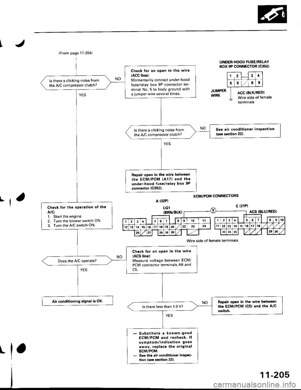
(From page 11-204)
Check for an open in the wir€(ACC linel:Momentarily connect underhood
fuse/relay box 9P connector teF
minal No. 5 to body ground with
a iumper wire several times.
ls there a clicking noise from
the IVC compressor clutch?
See air conditionor inspection(see 3oction 221.ls there a clicking noise from
the Py'C compressor clutch?
Repair open in the wire between
rhe ECM/PCM lAl7l and th6
under-hood fu3e/rolaY box 9P
connector lC352l.
Check for the oPeration of the
Alcl1. Start the engine.2. Turn the blower switch ON
3. Turn the AJC switch ON.
Chock tor an open in the wire
IACS linel:Measure voltage between ECM/
PCM connector terminals A9 and
c5.
Does the Ay'C operate?
Air conditioning signal is OK.Repair open in the wire b€tweenthe EcM/PcM lC5) and the A/c
3witch.ls there less than 1.0 V?
- Substiiute a known-goodECM/PCM and recheck ll
symptom/indication 9oesaway, .oplace the originalECM/PCM.- See the air condhioner insP€c_tion {see s€c{ion 22).
UNDER.HOOD FUSE/BELAYBOX 9P CONNECTOR 1C352)
12Ia
589
ACC (BLK/RI
Wire side ofACC (BLK/REDI
Wire side of female
terminals
JUMPERWIRE
ECM/PCM CONNECTORSrfA t32P)
LGlc {31Pl
t
(BRN/BLK)ACS IBLU/RED)
I23a9101t3I89t0
121315l611la1920232att12't3la't5t617ta
25272A2930232a2930
Wire side of lemale terminals
Page 476 of 2189

I
JUMP€RWIRE
UNDER-HOOO FUSE/RELAYsox 9P coNNEcroR lca52l
123a
5689
ACC (8LK/REDI
Wire side ofterminals
ECM/PCM CONNECTORS
A (32P1
female
Wire side of {emale terminals
(From page 11-206)
Check for an open in the wite
IACC lino):Momentarily connect under_hood
luse/relay box 9P connector teF
minal No. 5 to body ground with
a jumper wire several times.
ls there a clicking noise from
the Iy'C compressor clutch?
S6e air conditioner insPoction
l3oa section 221ls there a clicking noise lrom
the ly'C compressor clutch?
Ropair open in tho wilo betwg€n
the ECM/PCM lA17) and the A/C
clutch rolay.
Chock for the oporation of lho
AIC:1, Start the engine.
2. Turn the blower switch ON
3. Turn the ray'C switch ON.
Check lor an open in the wiro(ACS lino):Measure voltage between ECM/
PCM connector terminals A27
and 820.
Does the Iy'C operate?
Air conditioning signal is OK.Repair op6n in the wiro bctwoon
lhe ECM/PCM lA27l and tho A/C
3witch.ls voltage lessthan 1.0 V?
- Sub6iitut€ r known€ood ECtt /PCM and rccheck. ll sYmP-
tom/indication 9oe3.waY,replaca the original ECM/PCM- See the ai. condhionGr in3p€c-tion lsee soc{ion 221.
11-207
Page 487 of 2189

ldle Control System
{
(
a
Clutch Switch Signal (Dl6YS engine with M/Tl
This signals the ECM when the clutch is engaged.
A {32P}
ECM CONNECTORS
LGl (BRN/BLK)
\-
cLsw(RED}
Inrpaction ot dutch rwitch signal.
Check for on opon in the wiro(CLSW linel:'!. Turn the ignition switch ON (ll).2. Measure voltage betweon ECt!4connector terminals C29 andA9.
Ch.ck tho clutch switch:1. Turn the ignition switch OFF.2. Disconnect the 2P connectorfrom the clutch switch.3. Turn the ignition switch ON (ll).4. Measure voltage b€tween ECMconnector terminals C29 and
ls thare approx. 5 V?
ls there approx. 5 V?
Check for a short in th6 wire(CLSW line)l1. Turn the ignition swirch OFF.2. Disconnect the ECM connector C (31P)trom the ECM.3. Check lor continuity betweenECM connector terminal C29and body ground.
Chcck for an open in thg wire{CLSW linel:1. Depress the clutch pedal.2. Moasure voltage between ECMconnector torminals C29 andA9.
Repair short in the wirc betweentho ECM {C291 and tho clurchswitch.
Sub3titutg a known-good ECMand rechock, It p.e3cribed vohagoi! now available, roplace the orig-inal ECM.
Wire side of female terminals
26189101l12t3'tat5l617l822
o
(To page 11-219)
11-218
!
Page 488 of 2189
{From page 11-218)
Check lho clutch switch:
1. Turn the ignition switch OFF.
2. Disconnect the 2P connector
from the clutch switch.
3. Check lor continuity between
the clutch switch connector
terminals No. 1 and No.2 with
the clutch pedal depressed
ls voltage less than 1.0 V?
- Adiu3t the clutch swiich.- Reolace lhe clutch switch.
Check for an open in tha wiie:
1. Turn the ignition switch ON lll)
2. Measure voltage between the
clutch switch connector terml'nal No. 1 and body ground with
the clutch pedal depressed.
Repair op€n in the wire betwoen
the EcM (C291 and thc clutch
swilch.ls there approx. 5 V?
Repair open in BLK wire betweenthe clutch switch and Gircl.
Clutch switch signal is OK.
CLUTCH SWITCH 2P CONNECTOR
j-t -
Terminal side of male
termrnals
CLUTCH SWITCH 2P CONNECTOR {C41',
-f--r
I'l'l-l_-
clsw 1;1tREDr Y
Wire 6ide of lemaleterminals
I
lr,
11-219
Page 507 of 2189

Fuel Supply System
PGM-FI Main Relay (cont'dl
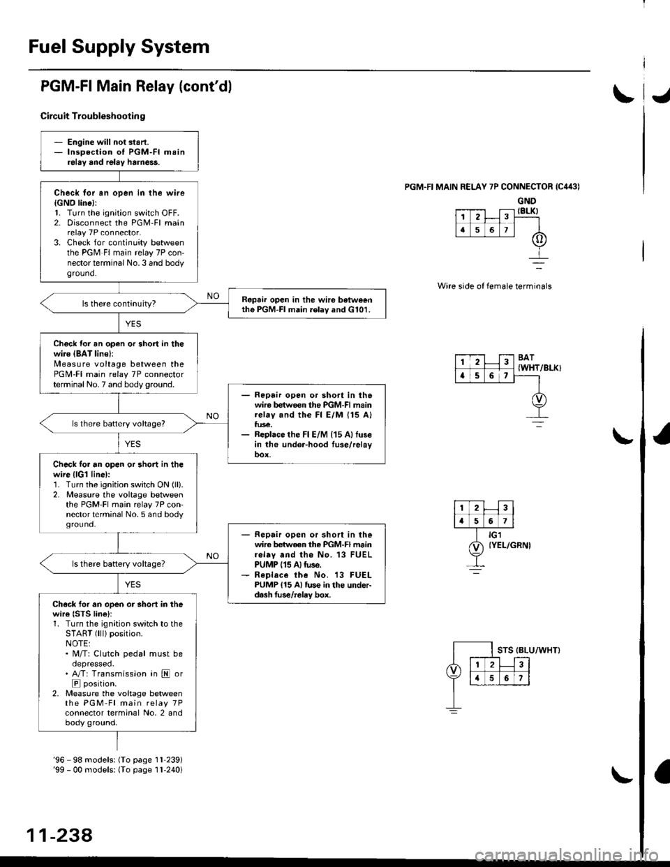
Circuit Troubleshootin g
PGM.FI MAIN RELAY 7P CONNECTOR {C443)
GND{8LK)
Wire side of female terminals
/BLK}
- Engine will not start.- lnsoection of PGM-FI mainrelay and relay harne$.
Check for an open in the wire{GNO line}:l. Turn the ignition switch OFF.2. Disconnect the PGM-Fl mainrelay 7P connector.3. Check for continuity betweenthe PGM Fl main relay 7P con-nector terminal No.3 and bodyground.
Ropai. open in the wir€ betweenthe PGM-FI main .elav and G101.
Check for an open or short in thewire {BAT lin€}:N4easure voltage between thePGM-FI main relay 7P connectorterminal No. 7 and body ground.- Repair open or sho.t in thewire between the PGM-FI mainrelay and the Fl E/M {15 A}fus€.- Replace the Fl E/M (15 Allu3ein the under-hood fuse/relayoox.
ls lhere battery voltage?
Check tor an open or short in thewire {lGl line):1. Turn the ignition switch ON (ll).
2. Measure the voltage betweenthe PGM-Fl main relay 7P con'nector terminal No. 5 and bodyground.- Repair open or short in thewire betwoen the PGM-FI mainrelav and the No. 13 FUELPUMP (15 A)tuse.- R€place the No. 13 FUELPUMP {15 A} tus€ in the under-d.sh fus€/relay box.
ls there battery voltage?
Ch.ck for an open or short in thewire {STS lino}r1. Turn the ignition switch to theSTART (lll) position.NOTE:. M/T: Clutch pedal must beoepresseo.. A/T: Transmission in E or
E position.2, Measure the voltage betweenthe PGM-Fl main relay 7Pconnector terminal No, 2 andbody ground.
12
[,a567
123BAT
{WHTa56,
'96 98 models: (To page 1l 239)'99 - 00 models: (To page I l-240)
11-238,
Page 536 of 2189

1\
Evaporative Emission (EVAPI Controls
Description
The evaporative emission controls are designed to minimize the amount of fuel vapor escaping to the atmosphere. The
system consists of the foliowing components:
A. Evaporative Emission (EVAP) Control Canisto]
An EVAP control canister is used for the temporary storage of fuel vapor until the fuel vapor can be purged from the
EVAP control canister into the engine and burned.
B. Vapor Purge Control System
EVAP control canister purging is accomplished by drawing fresh air through the EVAP control canister and into a port
on the intake manifold. The purging vacuum is controlled by the EVAP purge control solenoid valve.
I'96 D16Y5 engine,'96 Dl6Y7 engine,'96 D16Y8
engine (sedan),'97 D16Y5 engine,'97 D16Y7
engine (couper KA, KC models, sedan: KA, Kc'
KL iDX) models, hatchback: all models), '97
D 16Y8 engine (sedan: KA, KC models)l
I'96 D16Y8 engine (coupe),'97 D16Y7 engine
(coupe: KL model, sedan: KL (LX) model)"97
D16Y8 engine (coupe: all models, sedan: KL model)'98-all models,'99-all models,'00-all modelsl
I
c.
D.
or
l'lc COMPRESSOR CLUTCH ON
and
INTAKE AIR TEMPERATURE ABOVE 160"F (41'C)
Fuel Tank Vapor Control System
When fuel vapor pressure in the fuel tank is higher than the set value of the EVAP two way valve, the valve opens and
regulates the flow of fuel vapor to the EVAP control canister.
Onboard Refueling Vapor Recovery (ORVRI System {'99 - 00 models}
During refueling. the oRVR {onboard Refueling Vapor Recovery) vent shut valve opens with the pressure in the fuel
tank. and feeds the fuel vapor to the EVAP control canister.
t(cont'd)
11-267
EVAP PURGE CONTROL SOLENOID VALVE DUTY CON-
TROLLED AFTER STARTING ENGINE
ENGINE COOLANT TEMPERATURE ABOVE 154'F {68"C)
INTAKE AIR TEMPERATURE ABOVE 32'F (O'C)
and
VEHICLE SPEED ABOVE O MILE (O KM/h}
ENGINE COOLANT TEMPERATURE ABOVE 154'F (68'C)
Page 568 of 2189
J
t
Clutch
Speciaf Tools .......... ...........12-2
f lfustrated Index .......... ......12-3
clutch Pedal
Adjustment .................... 12'4
Clutch Master Cylinder
Removal/lnstallation ..... 12-5
Slave Cylinder
Removal/lnstallation .....12'6
Pressure Plate
Removal/lnspection ...... 12-7
Clutch Disc
Removal/lnspection ...... 12-8
Flywheel
Inspection ....................... 12-9
Replacement ....................................... 12-9
Clutch Disc, Pressure Plate
lnstallation ..................... 12-10
Release Bearing
Removal/lnspection ......12-11
f nstalfation .................,... 12-12
\
Page 569 of 2189
Special Tools
ItJ
Ref. No. Tool NumberDescriptionOty Page Reterence
o
\31(
@
!o/
OTJAF _ PM7O11A
OTJAF _ PM70124
07LAB - PV00100 or
07924, PD20003
07746 - 0010100
07749 - 00'�]0000
07936 - 3710100
Clutch Alignment Disc
Clutch Alignment Shaft
Ring Gear Holder
Attachment, 32 x 35 mm
Driver
Hand le
12-7
12-7 ,8, 10, 11't2-7,9,10,11
12 10
12-'tO
12-1 ,8, 10, 11
(r\aU
2-2