1997 HONDA CIVIC Water
[x] Cancel search: WaterPage 521 of 2189
Emission Gontrol System
System Description
The emission control system includes a Three Way Cata-lytic Convener (TWC), Exhaust Gas Recirculation (EGR)
system,. Positive Crankcase Ventilation (pCV) system andEvaporative Emission (EVAP) Control system. The emis-sion control system is designed to meet federal and stateemission standards.*: D16Y5 engine
Tailpipe Emission
Inspestion
@@ Do not smoke during ihis procedure. Keepany open flame away from your work area.
1. Start the engine. Hold the engine at 3,000 rpm withno load (in Park or neutral) until the radiator fancomes on. then let it idle.
2. Connect a tachometer.
Check and, if necessary, adjust the idle speed (see
page 11-220 - 223).
Warm up and calibrate the CO meter according to themeter manufacturer's instructions.
Check idle CO with the headlights, heater blower,rear window defogger, cooling fan, and air condition-er off.
NOTE: (Canada) Pull the parking brake lever up.Start the engine, then check that the headlights areoff.
CO mete. should indicate 0.1% maximum.
NOTE: '98 Dl6Y5 engine - lf the idle speed incress-es to 8101 50 rpm, this means the EVAp system ispurging the canister. To stop the purging temporari-ly. raise the engine speed above 1,000 rpm with theaccelerator pedal, then slowly release the pedal.
11-252
eFORWARD -
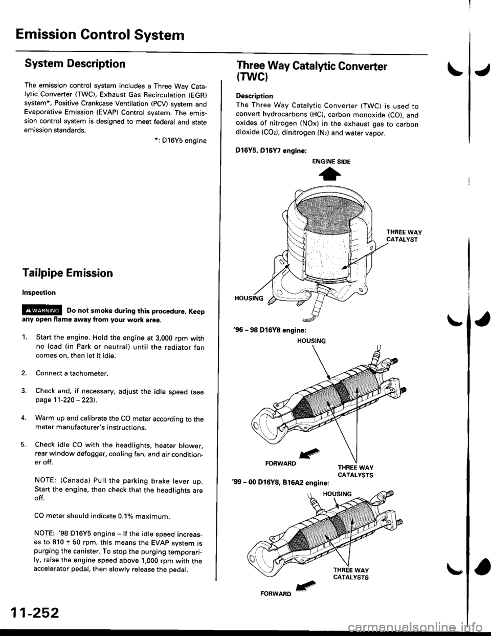
Three Way Catalytic Converter
(TWCI
Doscription
The Three Way Catalytic Converter (TWC) is used toconven hydrocarbons (HC), carbon monoxide (CO), andoxides of nitrogen (NOx) in the exhaust gas to carbondioxide (COr), dinitrogen (N,) and water vapor.
D15Y5, D16
, engine:
'99 - 00 D16Y8, 81642 engine:
ENGINE SIDE
t
Page 572 of 2189
Glutch Master Gylinder
IRemovaUlnstallation
CAU'NON:
. Do not sDill brake lluid onthevehicle;it may damage
the paint; if brake fluid does contact the paint, wash
it off immediatelY with water.
. Plug the end ofthe clutch line and reservoir hos€ with
a shop towelto prevent brake tluid from coming out
1. The brake tluid can be removed from the clutch
master cylinder reservoir with a syringe
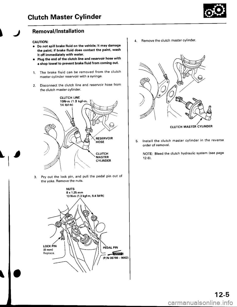
2. Disconnect the clutch line and reservoir hose from
the clutch master cylinder.
19N.m 11.9 kgf.m,14 tbf.ttl
[.
3. Pry out the lock pin, and pull the pedal pin out
the yoke. Remove the nuts
NUTS8 x 1 .25 mm13 N.m {'1.3 kgt.m,9.4lbf ft)
)
of
CLUTCH LINE
iffi,
4. Remove the clutch master cylinder.
CLUTCH MASTER CYLINDER
lnstall the clutch master cylinder in the reverse
order of removal.
NOTE: Bleed the clutch hydraulic system {see page
12-61,
12-5
Page 573 of 2189
Slave Gylinder
Removal/lnstallation
CAUTION:
. Do not spill brake tluid on the vehicle; it may damage
the paint; if brake fluid does contact th€ paint, wash
it off immodiatoly with water,
. Plug the end ot the clutch line with a shop towel to
prevsnt brake fluid from coming oul.
-61'srp", High Temp Urea crease (p/N
08798 - 90021.
: Brake Assembly Lube or equivalent rubber
grease.
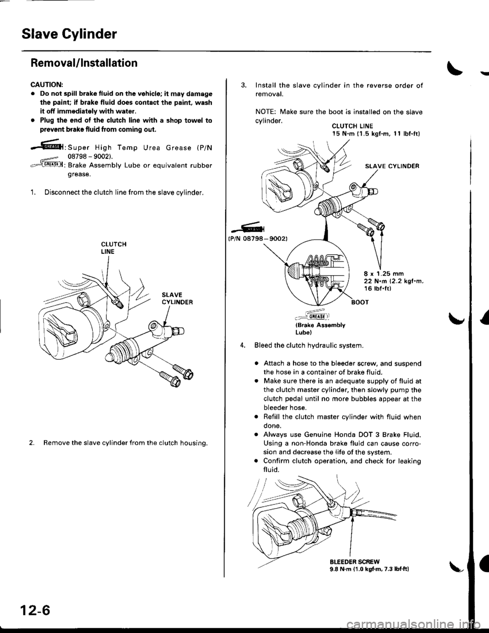
1. Disconnect the clutch line from the slave cvlinder.
2. Remove the slave cylinder from the clutch housing.
12-6
3. Install the slave cylinder in the reverse order of
removal.
NOTE: Make sure the boot is installed on the slave
cvlinder.. CLUTCH LINE15 N.m (1 .5 kgf.m, 1 1 lbf.It)
SLAVE CYLINDER
-G4(P/N 08798- 90021
8 x 1.25 mm22 N.m 12.2 kgl.n,16 lbl.lt)
:^..:i!!!!! :l
(Brak€ AssemblyLubol
Bleed the clutch hydraulic system.
a Attach a hose to the bleeder screw, and suspend
the hose in a container of brake fluid.
. Make sure there is an adequate supply of fluid at
the clutch master cylinder, then slowly pump the
clutch pedal until no more bubbles appear at the
bleeder hose.
. Refill the clutch master cylinder with fluid when
done.
. Always use Genuine Honda DOT 3 Brake Fluid.
Using a non-Honda brake fluid can cause corro-
sion and decrease the life of the system.
. Confirm clutch operation, and check for leaking
flu id.
Page 865 of 2189
Cooler Flushing
!!!@ To prevent iniury to. face and eyas, always
-ea. safetv glasses ot a face shield when using the
transmission flusher.
NOTE: This procedure should be performed before rein-
stalling the transmission.
1. Check the tool and hoses for wear and cracks before
using. lf wear or cracks are found, replace the hoses
before using.
Using the measuring cup, fill the tank with 2'l ounces
(approximately 2/3 full) of biodegradable flushing
fluid (J35944 - 20). Do not substitute with any other
fluid. Follow the handling procedure on the fluid
contarner.
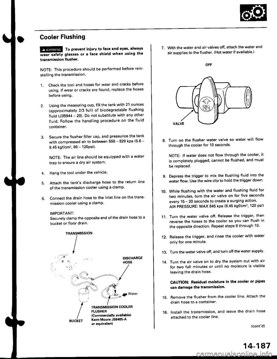
Secure the flusher filler cap, and pressurize the tank
with compressed air to between 550 - 829 kpa (5 6 -
8.45 kgflcm'�. 80 - 120Psi).
NOTE: The air line should be equipped with a water
trap to ensure a dry air system.
Hang the tool under the vehicle.
Attach the tank's discharge hose to the return line
of the transmission cooler using a clamp.
Connect the drain hose to the inlet line on the trans-
mission cooler using a clamP
IMPORTANT:
Securely clamp the opposite end oJ the drain hose to a
bucket or floor drain.
TRAMtssroN
TRANSMISSION COOLERFLUSHER{Commcrci.llY avail.blel
Kent-Moore J384O5'Aor equivelent
NS
I
{r Water
7. With the water and air valves off, attach the water and
air suDolies to the flusher' lHot water if available.)
8, Turn on the flusher water valve so water will flow
through the cooler for 10 seconds.
NOTE; lf water does not tlow through the cooler, it
is completely plugged. cannot be flushed, and must
be replaced.
9. Depress the trigger to mix the flushing fluid into the
water flow. Use the wire clip to hold the trigger down'
While flushing with the water and flushing fluid for
two minutes, turn the air valve on for five seconds
everv 15 - 20 seconds to create a surging action'
AIR PRESSURE: MAX 845 kpa {8.45 kgf/cm'�, 120 psi)
Turn the water valve off. Release the trigger, then
reverse the hoses to the cooler so you can flush in
the opposite direction. Repeat steps 8 through 10'
12, Release the trigger, and rinse the cooler with water
onlv for one minute
13. Turn the water valve off, and turn off the water supply
14. Turn the air valve on to dry the system out with air
for two full minutes or until no moisture is visible
leaving the drain hose.
CAUTION: Residual mobturo in tho cooler or pipas
can damage the transmksion'
15. Remove the flusher from the cooler line. Attach the
drain hose to a contalner.
16. Install the transmission, and leave the drain hose
attached to the cooler line
{cont'd)
10.
'11.
14-187
Page 866 of 2189

Transmission
17.
Cooler Flushing (cont'dl
Make sure the transmission is in the E position.
Fill the transmission with ATF, and run the enginefor 30 seconds or until approximately 0.95 f (1.0 USqt.,0.8 lmp qt.) is discharged.
Remove the drain hose, and reconnect the coolerreturn hose to the transmission (see page l4-192).
Refill the transmission with ATF to the oroDer level(see page 14-118).
18.
19.
b
14-18A
TOOL MAINTENANCE
1. Empty and rinse after each use. Fill the can with waterand pressurize the can. Flush the discharge line toensure that the unit is clean.
2. lf discharge liquid does not foam, the orifice may beblocked.
3. To clean, disconnect the plumbing from the tank atthe large coupling nut.
ORIFICE
GRT{G
Remove the in-line filter from the discharge side andclean if necessary.
The fluid orifice is tocated behind the filter.Clean it with the pick stored in the bottom of thetank handle, or blow it clean with air. Securelvreassemble all Darts.
FILLER CAP
Page 1028 of 2189
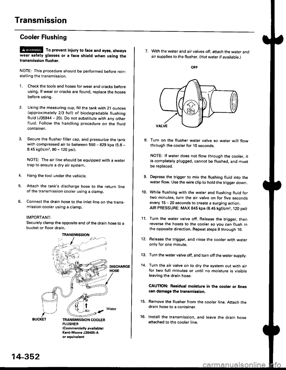
Transmission
Gooler Flushing
@ To prevent iniury to face and eyes, alwayswear safety glasses or a tace shield when using thetransmission flusher.
NOTE: This procedure should be performed before rein-stalling the transmission.
'1. Check the tools and hoses for wear and cracks before
using. lf wear or cracks are found, reDlace the hoses
before using.
4.
Using the measuring cup. fill the tank with 2,1 ounces(approximately 2/3 full) of biodegradable flushingfluid (J35944 - 20). Do not substitute with any otherfluid. Follow the handling procedure on the fluidcontatner.
Secure the flusher filler cap, and pressurize the tankwith compressed air to between 5S0 - 829 kpa (5.6 -
8.45 kgf/cm'�, 80 - 120 psi).
NOTE: The air line should be equipped with a watertrap to ensure a dry air system,
Hang the tool under the vehicle.
Attach the tank's discharge hose to the return lineoi the transmission cooler using a clamp.
Connect the drain hose to the inlet line on the trans-mission cooler using a clamp.
IMPORTANT:
Securely clamp the opposite end ofthe drain hose to abucket or floor drain,
t
TRANSMISSION COOLERFLUSHER{Commercially available)Kent-Moore J384O5-Aor oouivalent
TRANSMISSION
14-352
7. With the water and air valves off, attach the water andair supplies to the flusher. (Hot water if available.)
8. Turn on the flusher water valve so water will flowthrough the cooler for 10 seconds.
NOTE: lf water does not flow through the cooler, itis completely plugged, cannot be flushed, and mustbe replsced.
9. Depress the trigger to mix the flushing fluid into thewater flow. Use the wire clip to hold the trigger down.
'10. While flushing with the water and flushing fluid fortwo minutes. turn the air valve on for five secondsevery 15 - 20 seconds to create a surging action.AIR PRESSURE: MAX 845 kpa (8.45 kgflcmr, 120 psi)
11. Turn the water valve off. Release the trigger, thenreverse the hoses to the cooler so you can flush inthe opposite direction. Repeat steps 8 through 10.
12. Release the trigger. and rinse the cooler with wateronly for one minute.
13, Turn the water valve off, and turn off the water supply.
'14. Turn the air valve on to dry the system out with airfor two full minutes or until no moisture is visibleleaving the drain hose.
CAUTION: Rosidual mobturo in the qooler or linescln damage the transmission,
15. Remove the flusher from the cooler line. Attach thedrain hose to a container.
16. Install the transmission. and leave the drain hoseattached to the cooler line.
Page 1029 of 2189
![HONDA CIVIC 1997 6.G Workshop Manual l.
17.Make sure the transmission is in the E] position.
Fill the transmission with cvT Fluid, and run the
engine for 30 seconds or until approximately 0 95 {
(1.0 US qt.,0.8 lmp qt.) is discharged.
Re HONDA CIVIC 1997 6.G Workshop Manual l.
17.Make sure the transmission is in the E] position.
Fill the transmission with cvT Fluid, and run the
engine for 30 seconds or until approximately 0 95 {
(1.0 US qt.,0.8 lmp qt.) is discharged.
Re](/manual-img/13/6068/w960_6068-1028.png)
l.
17.Make sure the transmission is in the E] position.
Fill the transmission with cvT Fluid, and run the
engine for 30 seconds or until approximately 0 95 {
(1.0 US qt.,0.8 lmp qt.) is discharged.
Remove the drain hose, and reconnect the cooler
return hose to the transmission (see page 14-355)
Refill the transmission with CVT Fluid to the proper
level (see page 14-299).
18.
'19.
.l ,
TOOL MAINTENANCE
1. Empty and rinse after each use. Fill the can with water
and pressurize the can. Flush the discharge line to
ensure that the unit is clean.
2, lf discharge liquid does not foam, the orifice may be
blocked.
3. To clean, disconnect the plumbing from the tank at
the large couPling nut.
FILTER
\
\- 0--D
i
I
O.RING
Remove the in-line tilter from the discharge side and
clean if necessary'
The fluid orifice is located behind the filter. Clean it
with the pick stored in the bottom of the tank han-
dle. or blow it clean with air. Securely reassemble
all parts.
COUPLINGNUT
II
-@q
\ORIFICE
FILLER CAP
14-353
Page 1161 of 2189
I
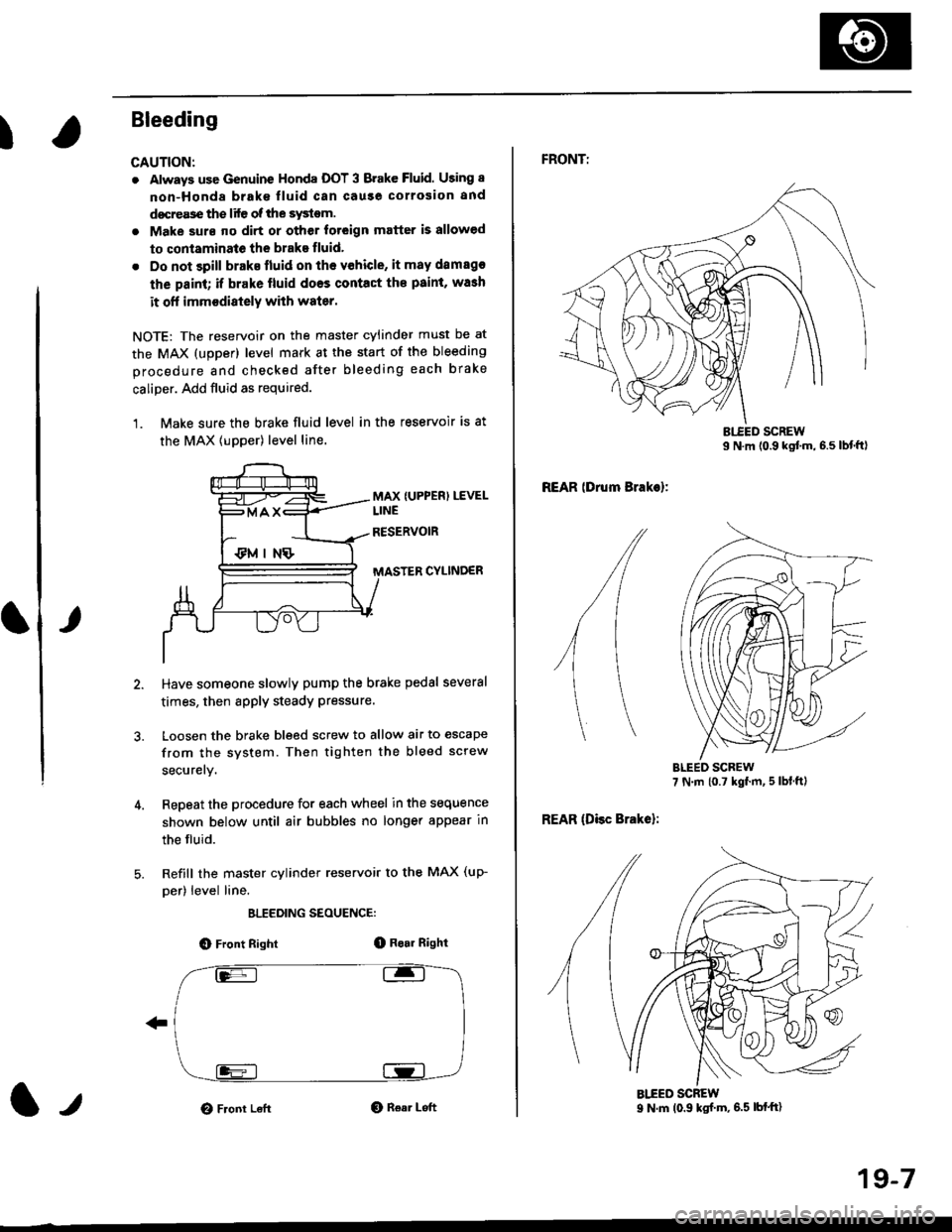
Bleeding
CAUTION:
. Always use Genuine Honda DOT 3 Brake Fluid. Using 8
non-Honda brak€ fluid can cause corrosion and
docrea3e the life of the system.
. Make surs ||o dirt or other foteign matter is allowed
to contaminate the brake fluid,
. Do not spill brake lluid on the vehicle, it may damago
the paint; if brake lluid doos contac{ the paint, wash
it ofl imm€diately with water.
NOTE: The reservoir on the master cylinder must be at
the MAX (upper) level mark at the start of the bleeding
procedure and checked after bleeding each brake
caliper. Add fluid as required.
1. Make sure the brake fluid level in the reservoir is at
the MAX lupper) level line.
MAX {UPPER) LEVEL
CYLINDER
Have someone slowly pump the brake pedsl several
times, then apply steady Pressure.
Loosen the brake bleed screw to allow air to escape
from the system. Then tighten the bleed screw
securely.
Repeat the procedure for each wheel in the sequence
shown below until air bubbles no longer appear in
the fluid.
Refill the master cylinder reservoir to the MAX (up-
per) level line.
ELEEDING SEOUENCE:
O Front Right(D Bo.r Right
O Front LeftO Rear Left1,,
19-7
FRONTT
REAR lDrum Brakel:
REAR (Disc Brake):
AIEED SCREW9 N.m (0.9 ksf m, 6.5 lbf'ft)