Page 194 of 2189

I
Cylinder Head
Installation
lnstall the cylinder head in the reverse order of removal:
NOTE:
. Always use a new head and manifold gasket.. The cylinder head gasket is a metal gasket, Take carenot to bend it.
. Rotate the crankshaft, set the No. 1 piston at TDC (seepage 6-63).
. Do not use the middle cover and lower cover forstorang removed items.. Clean the middle cover and lower cover before instal_lation.
o Replace any washers that are damaged or deteriorated.
1. Install the cylinder head gasket, dowel pins and thehead oil control orifice on the cylinder head.
NOTE: Clean the oil control orifice when installing.
DOWEL PIN
6-84
2, Tighten the cylinder head bolts in two steps. In thefirst step, tighten all bolts in sequence to about 29N.m (3.0 kgf.m, 22 tbf.ftl. ln the final step, tighten inthe same sequence to 83 N.m (8.S kgf.m,6t lbf.ft).
NOTE:
. Apply clean engine oil to the bolt threads andunder the bolt head.. We recommend using a beam-type torquewrench. When using a preset-type torque wrench,be sure to tighten slowly and not to overtighten.. lf a bolt makes any noise while you are torquing it,loosen the bolt, and retighten it from the 1st step.
CYLINDER HEAD BOLT TOROUE SEOUENCE
11x 1.5 mm83 N.m 18.5 kgf.m, 61 tbf.ftl
Install the intake manifold and tighten the nuts in acflsscross pattern in two or three steps, beginningwith the inner nuts.. Always use a new intake manifold gasket.
Install the exhaust manifold and tighten the newself-locking nuts in a crisscross pattern in two orthree steps. beginning with the inner nuts.. Always use a new exhaust manifold gasket.
4.
Page 198 of 2189

Engine Block
Speciaf Tools ..........." 7-2
lllustlated Index ...................."..'.......... 7-3
Flywheel and Drive Plate
Repf acement """'.' 7-7
Connecting Rod and Crankshaft
End Play ..........."....7-8
Main Bearings
Clearance ............... 7-9
Selection ................7-10
Connecting Rod Bearings
clearance ....'.......... 7-11
Selection ................ 7-11
Pistons and Crankshaft
Removaf ................. 7 -12
Crankshaft
Inspection ."".........7-14
Pistons
Inspection ......"'.....7-15
fnstaffation .............7-23
Cylinder Block
lnspec'tion ..............7-16
Bore Honing ..........7-17
Piston Pins
Removal ...,...........'.7-17
lnstallation .............7-18
Inspection .'............7-19
Connecting Rods
Selection ................7-18
Piston Rings
End Gap ..........".."' 7'2O
Repfacement .........7-2O
Ring-to-Groove Clearance ...........'.'. 7 -21
Afignment .......""'.. 7'21
Crankshaft Oil Seal
fnstaffation .............7-22
Crankshaft
fnstaffation ..-.-..'.".' 7'23
Oil Pan
lnstallation .............7-26
Oil Seals
fnstaffation ....""""' 7-29
r-f
Page 200 of 2189

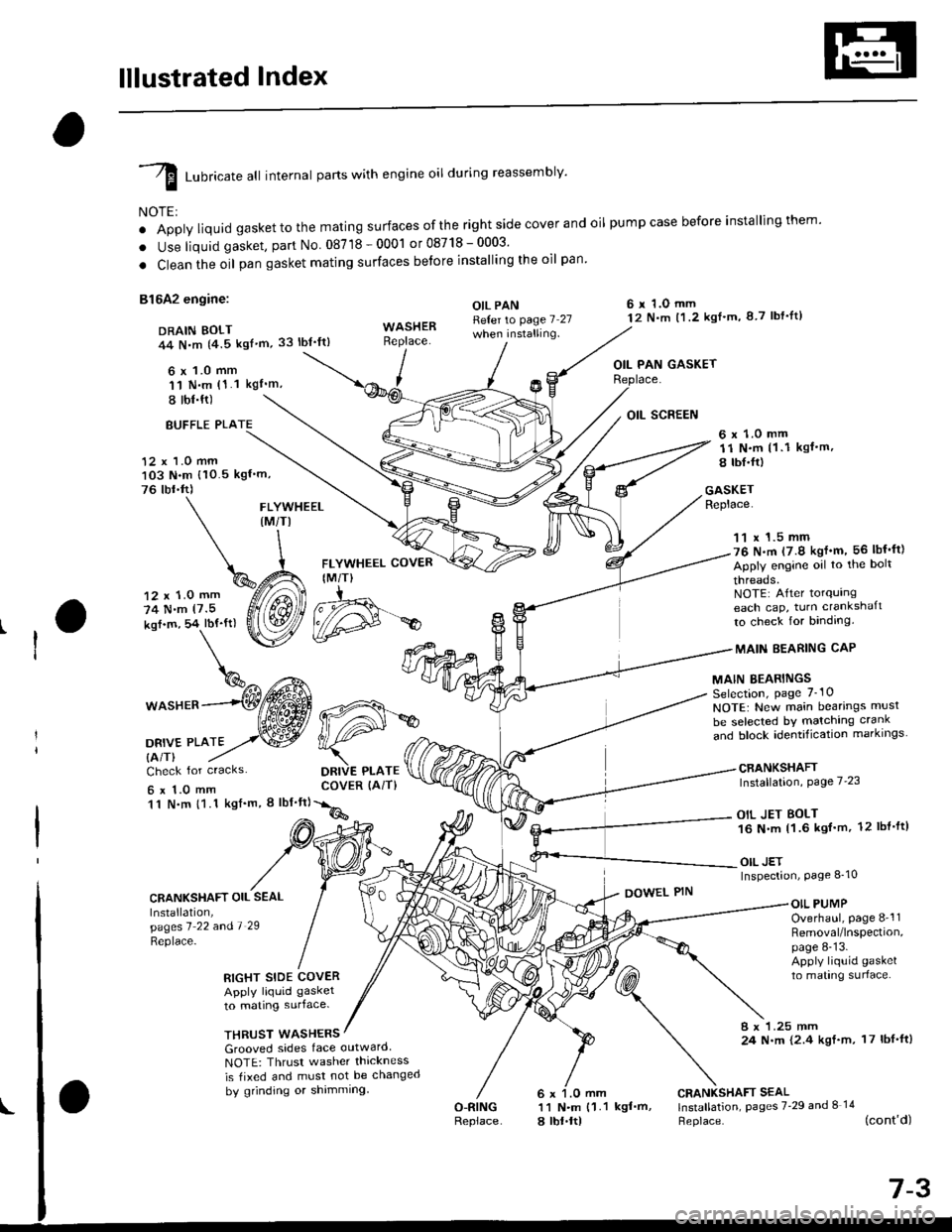
lllustrated Index
I runricate att internal parts with engine oil during reassembly'
NOTE:
o Apply liquid gaskettothe mating surfaces ofthe right side cover and oil pumpcase before installingthem'
. Use liquid gasket, part No 08718-0001 or08718-0003'
. Clean the oil pan gasket mating surfaces betore installing the oil pan
81642 engine:
DRAIN BOLT44 N,m {4.5 kgf'm,33 lbt'ft)
6 x 1.0 mm'11 N.m (1.1 kgI'm,
I tbl.ft)
OIL PANReter to page 7 27when installing.
6 r 1.O mm12 N.m t1.2 kgl'm, 8 7 lbf'lt)
OIL PAN GASKET
BUFFLE PLA
12 x 1.0 mm103 N.m {10.5 kgf'm,
76 tbr.ft)
6 x 1.0 mm11 N.m (1 .1 kgf.m,
8 tbI.fr)
GASKETReplace.FLYWHEEL(M/TI
12 x 1.0 mm
74 N.m (7.5
kof.m, 54 lbf'ft)
1^c{Eb\%^ t*^
*o"rr^--(Wffi
oa*,trto2,.w
FLYWHEEL COVER
IM/T)
DRIVE PLATECOVER (AiT)
11 x 1.5 mm76 N.m (7.9 kgf'm, 56 lbf'ft)
Apply engine oil to the bolt
threads.NOTE: After torqurngeach cap, turn crankshaft
to check for binding.
MAIN EEARING CAP
MAIN BEARINGSSelection, page 7_10
NOTE: New main bearings musl
be selected bY matching crank
and block identification markrngs
CRANKSHAFTInstallation, Page 7'23
OIL JET BOLT16 N.m 11.6 kgf'm, 12 lbl'ft)
OIL JETInspection, Page 8_10
Check for cracks
6x1.0mm11 N.m {1.1 kgf'm, I lbf'ft}
CRANKSHAFT OIL SEAL
Installation,pagesl 22 andl 29
Replace-
DOWEL PINOIL PUMPOverhaul, page 8-'l1Removal/lnspection,page 8-13.Apply liquid gasket
to mating surlace.RIGHT SIDE COVERApply liquid gasket
to mating surface.
THRUST WASHERS8 x 1.25 mm24 N.m {2.4 kgf.m, 17 lbf'ft)Grooved sides face outward
NOTE: Thrusr washer thickness
is tixed and must not be changed
by grinding or shimming
O-RINGReplace
CRANKSHAFT SEAL11 N.m {1.1 kgf'm, lnstallation, pages 7'29 and I 14
a lbt.ltl Heplace. (cont'd)
d#*
Page 201 of 2189

lllustrated Index
(cont'dl
I Luoricate att internal parts with engine oil during reassembly.
NOTE:
' Apply liquid gasket to the mating surfaces ofthe rightside coverand oil pumpcase before installingthem.. Use liquid gasket, part No. 08718 - 0001 or 087,18 _ OOO3.. Clean the oil pan gasket mating surfaces before installing it.
D16Y7 engine:6 x 1.0 mm12 N.m (1.2 kgt.m.8.7 tbf.tr)DRAIN BOLT44 N.m {4.5 kgt.m.33 tbt.ttl
,(
I
I
OIL PAN GASKETFLYWHEEL COVERIM/T)6x 1.0 mm12 N.m ('l .2 kgt.m, 8.7 tbt.trl
OIL PANRefer to page 7-27
Apply liquid gasker tothese points.
Replace.
WASHERReplace.12 x '1.0 mm118 N.m{12.0 kgt.m, 87 tbf.tr}
11 x 1.5 mm51 N.m15.2 kgl.m,38lbtftl
Apply engine oilto the boltthreads.NOTE: After torquingeach cap, turn the crankshaftto check for binding.
MAIN BEARINGSSelection, page 7-10
MAIN BEARING CAP
CRANKSHAFTInstallation, page 7 23
NOTE: New main bearings mustbe selected by matching crankand block identification markings.
6 r 1.0 mm11 N.m {1.1
6 x 1.0 mm11 N.m 11.1
ksI.m, 8 lbt.ft)
OIL SCREEN
kgt.m, 8 lbf.trl
Check for cracks.
CRANKSHAFT OIL SEALInstallation,pages 1 22 a^d 7-29
\:eprace'
GASKETReplace.
6 x 1.O mm11 N.m {1.1 kgt.m,8 rbt.frl
RIGHT SIDE COVERApply liquid gasker1o matrng surface,
OIL PUMPOverhaul, page 8-12Bemoval/lnspection,page 8-13
DOWEL PIN
WASHERSGrooved sides face outward.NOTE: Thrust washer thicknessis fixed and must not be changedby grinding or shimming.
CRANKSHAFT SEAL
l.j"Ji:l"^ pages z.2e --.S)
Replace.
6 x 1.0 mm11 N.m {1.18 tbt.fr)
7-4
BREATHING PORT COVERMOUNT BOLTS6 x 1.0 mm11 N.m {1.1 kgt.m, 8 tbf.fr}Apply liquid gasker tothe boh threads.
DOWEL PIN
Page 202 of 2189

D16Y5, D16Y8 engines:
DRAIN BOLT39 N.m 14.0 kgt'm,
Apply liquid gasket to
these points.
OIL PANRefer to page 7-25
when installing.WASHERReplace.
29 lbl.tt)
\
\^
6 x 1.0 mm q%
P
I
FLYWHEEL COVER(M/T}
12 x 1.0 mm118 N.m(12.0 kgt.m, 87 lbt'ft)
FLYWHEEL (M/TI
t2 N.m 11.2 kgf'm,
8.7 lbl.ftl
11 x 1.5 mm
51 N.m(5.2 kgf'm, 38 lbf ftl
Apply engine oiltothe bolt
threads.NOTE: Aftertorquingeach cap, turn crankshaft
to check for binding.
MAINBEARING
MAIN BEARINGSSelection, page 7-10NOTE: New main bearings must
be selected by matching crank
"nJ lr."i io"irriti"",ion-markings. --------*-i6{\
CRANKSHAFTInstallation, page 7-23
6 r 1.0 mm11 N.m (1 1 kgf'm, I lbf'ttl
OII PAN GASKETReplace.
DRIVE PLATE COVER
{A/T or CVT)
12 r 1.0 mm
74 N.m
17.5 kgl.m, 54 lbf'ft)
DBIVE PLATE {A/T or CVTI
Check for cracks
6 x 1.O mm11 N.m {1.1 kgl'm,
8 tbl.ftl
CRANKSHAFT OIL SEAL
lnstallation,pages 7'?1 and '1 '28
Replace.
RIGHT SIDE COVER
Apply liquid gasket
to mating surface.
OIL SCREEN
GASKETReplace.
OIL PUMPOverhaul, page 8_12Removal/lnspection,page 8-13Apply liquid gasket
to mating surface.
DOWEL PIN
WASHEFS
Grooved sides tace outward
NOTE: Thrust washer thickness
is fixed and must not be changed
bV grinding or shimming.
CRANKSHAFT SEALInstallation, pages 7 29
and 8-14Replace.
BREATHING PORT COVER
MOUNT BOLTS6 x 1.O mm11 f{..n (1.1 kgf'm, 8 lbf'fl)
Apply liquid gasket to
the bolt threads.
O.RINGReplace.
6 x 1.0 mm
11 N.m (1 1 kgl'm,
8 tbr.ftl
(cont'd)
7-5
\
OOWEL PIN
Page 203 of 2189

lllustrated Index
(cont'd)
NOTE: New rod bearings must be selected by matching connecting rod assembly and crankshaft(see page 7,11).identification markings
Lubricate all internal parts with engine oil duringreassembtv.
PISTON INSTALLATION DIRECTION:
EXHAUST
4\/=\6\z\
\e/!rqrf/
INTAKE
PISTON RINGSReplacement. page 7-20Measurement, pages 7 20 andj-21Alignment, page 7-21
PISTON PINRemoval, page 7,17Installation, page 7-18Inspection, page 7,19
CONNECTING RODEnd play, page 7-8Selection, page 7,18
CONNECTING RODBEARINGSClearance, page 7 11Selection, page 7-11
CONNECTING ROD BEARING CAPInstallation, page 7-23NOTE: lnstall caps so thebearing recess is on thesame side as the recessin the rod.
PISTONInspectron, page 7-15NOTE: Betore removing the piston, inspect thetop of the cylinder bore for carbon build-up orridge. Bemove ridge if necessary, page 7-13
ENGINE BLOCKCylinder bore inspection, page 7-16Warpage inspection, page 7,'16Cylinder bore honing, page 7,17
Inspect top of each cylinder borefor carbon build-up or ridgebefore removing piston.Remove ridge if necessary, page 7-13
CONNECTING ROD CAP NUT816A2 €ngin6:9 x 0.75 mm{0 N.m (4.1 kgt m, 30 tbf.ftlD16Y5, Dl6Y7. D16Y8 engines:8 x 0.75 mm3l N.m {3.2 kg{.m,23 tbt.fr)Apply engine oiltothe bolt threads.NOTE: After torquing each bearingcap, rotate crankshaft tocheck for binding.
7-6
Page 204 of 2189
Flywheel and Drive Plate
Replacement
Manual Transmission:
816A2 engine:
Remove the eight flywheel bolts, then separate the fly-
wheel from the crankshaft flange. After installation'
tiohten the bolts in the sequence shown
RING GEAR HOLDER "-i
OTLAB PVOOlOO
D16Y5, D16Y7, D16Y8 engines:
Remove the six flywheel bolts, then separate the flywheel
from the crankshaft flange. After installation, tighten the
bolts in a crisscross Pattern.
RING GEABInspect ring gear
teeth lor wear or
damage.
RING GEARInspect ring gear
teeth lor wear orteetn lor wea( or /danase. ,///.'
12 x 1.0 mm103 N.m(10.5 kgf.m, 76 lbf.tt)
12 x 1.o mm1 18 N,m(12.0 kgI.m, 87 lbf.ftl
L
rurS;u'.\
$..3s'
Automatic Transmission:
Remove the six drive plate bolts, then separate the drive
olate from the crankshaft flange. Atter installation, tighten
the bolts in a crisscross Pattern.
t7.5 kgl.m, 54 lbl'ltl
12 x 1.0 mm74 N.m
7-7
Page 205 of 2189
Connecting Rod and Crankshaft
End Play
Connecling Bod End Play:
Standard (Newl: 0.15 - 0.30 mm
10.006 - 0.012 inlService Limit: 0.40 mm (0.016 inl
lf out-of-tolerance. install a new connecting rod.lf still out-of-tolerance, replace the crankshaft (seepages 7-12 and 7-23).
a
a
7-8
\
Push the crankshaft firmly away from the dial indicator,and zero the dial against the end of the crankshaft. Thenpull the crankshaft firmly back toward the indicator; dialreading should not exceed service limtr.
Grankshaft End Play:
Standard (Newl: 0.10 - 0.35 mm(0.00,f - 0.01,t inlServic€ Limit 0.it5 mm (0.018 in)
. lf end play is excessive, inspect the thrust washersand thrust surface on the crankshaft. Replace Darts asnecessary.
NOTE: Thrust washer thickness is fixed and must not bechanged either by grinding or shimmrng.Thrust washers are installed with grooved sides facingoutward.