Page 794 of 2189

Stall Speed
Test
CAUTION:
. To prev€nt transmission damage, do not t6st stall speed for more than ro sgconds at a time.. Do not shift the levor while raising the engine speed.. Bo sule lo remove the pressure gauge betoro testing stall speed.
'1. Engage the parking brake, and block the front wheels.
2. Connect a tachometer to the engine, and start the engine.
3. Make sure the Ay'C switch is OFF.
4. After the engine has warmed up to normal operating temperature (the radiator fan comes on). shift into E position.
5. Fully depress the brake pedal and accelerator for 6 to g seconds, and note engine speed.
6. Allow two minutes for cooling, then repeat the test in @ and @ positions.
NOTE:
. Stall speed tests should be used for diagnostic purposes only,. Stall speed should be the same in o., E and E positions.
Stall Spsed RPM:
Specification: 2.700 rpm
Service Limit: 2,550 - 2,850 rDm
TROUBLEPROBABLE CAUSE
. Low fluid level or ATF pump outDur. Clogged ATF strainer. Pressure regulator valve sluck closeo. Slipping clutch
. Slippage of 4th ctutch
. Slippage of 2nd clutch
. Slippage of lst clut"tr or. t"t g""io*-*"y "lut"h
Stall rpm high in D., E and E positions
Stall rpm high in El position
Stall rpm high in E posirion
Stall rpm high in E position
Stall rpm low in LDa . El and E positrons. Engine output low. Torque converter one-way clutch slipping
14-116
Page 797 of 2189

Pressure Testing
@I While testing, be caroful of th€ rotating front wheels.
. Make sure lifts, iacks, and satoty stands are placod properly (see section 1)'
CAUTION:
. Beforo iesting, be sure the transmission fluid is tilled to tho proper level'
. Warm up tho engine before testing'
1. Raise the vehicle (see section 1).
2. Warm up the engine, then stop the engine and connect a tachometer'
3. Connect the oil pressure gauges to each inspection hole.
TOROUE: 18 N.m (1.8 kgf'm, 13 lbnft)
cAUTloN: connact the oil pressuro gauges securely; be suro not to allow dust and other foreign Parlicles to entel
the inspestion holos'
A/T OIL PRESSURE GAUGESET w/PANEL07t06 - 0020400
A/T LOW PRESSURE GAUGE
SET WPANEL07406 - 0070300
A/T OIL PRESSURE HOSEADAPTER07Mru - PY0120(4 requiJedl
A/T OIL PBESSURE HOSE
2210 mmOTMAJ - PY4{)llA
14 roquircdl
Start the engine, and measure the respective ptessure as follows'
a Line Pressure
. 1st Clutch Pressure
. 2nd,3rd and 4th Clutch Pressure
Install a new washer and the sealing bolt in the inspection hole. and tighten to the specified torque'
TOROUE: l8 N.m (1.8 kgf'm,13lbf'ft)
NOTE: Do not reuse old sealing washers; always replace washers'
(cont'd)
14-119
Page 798 of 2189
Pressure Testing
(cont'd)
Line Pressure/1st Clutch Pressurc Measurement
1. Set the parking brake, and btock both rear wheels securely.
2. Start the engine, and run it at 2,OOO rpm.
3. Shift to N or E position, then measure line pressure.
NoTE: Higher pressure may be indicated if measurements are made in shift lever positions other than @ or @ positron.
4. Shift to tq;l position, hold the engine at 2,000 rpm, and measure 1st crutch pressure.
1ST CLUTCH PRESSUREINSPECTION HOLE(Marked with "1")
LOCK.UP CONTROLSOLENOID VALVE A/8ASSEMBLY
VALVE A/B ASSEMBLY
PRESSURESHIFT LEVER
POS|TtONSYMPTOMPROBABLE CAUSEFLUID PRESSURE
StandardService Limit
LineN orENo (or low)
lrne pressureTorque converter,
ATF pump, pres-
sure regutator.
torque converter
check valve
830 - 880 kPa
{8.5 - 9.0 kgf/cm?,
120 - 130 psi)
780 kPa(8.0 kgf/cm'�, 110 psi)
1st ClutchD;lNo or low 1st
pressure
1st Clutch
\
14-120
Page 805 of 2189

O ROLLER
O COLLAR
O o-RING Replace.
@ FEED PIPE FLANGE
@ O-RING Replace.
@ SNAP RING
€) 3RD CLUTCH FEED PIPE
€) COUNTERSHAFT LOCKNUT (FLANGE NUT)
23 x 1.25 mm Replace.
o coNlcAL SPRING WASHER Replace.
@ PARK GEAR
@ ONE.WAY CLUTCH
@ COUNTERSHAFT lST GEAR
@ NEEDLE BEARING
@ COUNTERSHAFT lST GEAR COLLAR
@ o-RlNGs Replace.
@ END covER GASKET Replace.
E) DOWEL PINS
@ PARK PAWL STOP
@ LocK WASHER Replace.
@ PARK STOP Selective part
€D PARK LEVER
@ PARK LEVER SPRING
€D DRAIN PLUG
€) SEALING WASHER Replace
@ o-RING Replace.
@ COUNTERSHAFT SPEED SENSOR
@) PARK PAWL
@ PARK PAWL SPRING
@ PARK PAWL SHAFT
@ LINEAR SOLENOID ASSEMBLY
@ LINEAR SOLENOID GASKET REPIACE.
@) END COVER
@ lsT CLUTCH FEED PIPE
@ O-RINGS Replace.
@ FEED PIPE FLANGE
C) SNAP BING
@ MAINSHAFT LOCKNUT (FLANGE NUTI 21 x 1 25 mm
Replace.
@ CONICAL SPRING WASHER RePlace
@) lST CLUTCH ASSEMBLY
@ o-RlNGs Replace.
€) THRUST WASHER
@) THRUST NEEDLE BEARING
@ NEEDLE BEARING
@ MAINSHAFT lST GEAR
@ MAINSHAFT lST GEAR COLLAR
@) ATF COOLER LINE
@ SEAUNG WASHERS Replace.
@ LINE BOLT
@ ATF DIFSTICK
@ ATF COOLER LINE
@ UNE BOLT
@ SEALING WASHERS Replace.
@ VEHICTT SPEED SENSOR
@ O-RING Replace.
TOROUE SPECIFICATIONS
Bolt/Nut No.Torque ValueSizeRemarks
6B
8F
12A.'l8D
2'tM
23C
'12 N'm (1.2 kgim,8.7 lbift)
14 N.m (1.4 kgf.m, 10 lbf'ft)
22 N.m (2.2 kgf.m, 16 lbf'ft)
28 N.m (2.9 kgf.m, 21 lbf'ft)
49 N.m (5.0 kgf.m, 36 lbf'ft)
78 N.m (8.0 kgf'm, 58 lbf'ft)
103 N.m {10.5 kgf'm,75.9 lbift)
6x1.0mm
6x1.0mm
8 x 1,25 mm
12 x 1.25 mm
18 x 1.5 mm
21 x 1.25 mm
23 x 1.25 mm
Line bolt
Drain plug
Mainshatt locknut: Left-hand threads
Countershaft locknut:
Left-hand threads
14-127
Page 827 of 2189

Inspection
a Clearance Measurement
NOTE: Lubricate all parts with ATF during assembly.
1, Remove the mainshaft bearing from the transmis-
sion housing (see Page 14-1741.
2. Assemble ths parts below on the mainshaft.
NOTE: Do not assemble the O-rings during inspec-
tlon.
LOCKNUTCONICAL SPRIIIG WASHER
SNAP RING
lST CLUTCH ASSEMBLY
TXRUST WASHER
1ST GEAR COLLAR
TRA SMISSIONHOUSII{G BEARING
THRUST WASHER
4TI{ GEAR COLLAR
2ND/4TH CLUTCHASSEMBLY
THRUST WASHER36.5 x 55 mmSelective part.
THBUST NEEDLEBEARING
2ND GEAR
AEABII{G
IHRUST NEEDLEBEARING
MAINSHAFT
3. Torque the mainshaft locknut to 29 N'm (3.0 kgf'm,
22 tbt,ftl.
NOTE: Mainshaft locknut has left-hand threads.
29 N'm t3.0 kgl'm, 22 lbt'ft)
Hold 2nd gear against the 2nd clutch' then measure
the clearance between 2nd gear and 3rd gear with a
feeler gauge.
NOTE: Take measurements in at least three places,
and use the av€rage as the actual clearance'
STANDARD: 0.05 - 0.13 mm 10.002 - 0.005 in)
THRUST WASHER,36.5 x 55 mm
(cont'd)
1+149
Page 832 of 2189

Gountershaft
Inspection (cont'dl
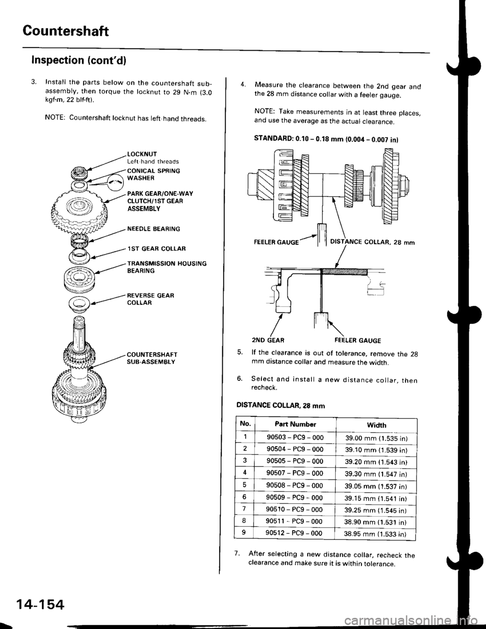
3. Install the parts below on the countershaft sub-assembty, then torque the locknut to 29 N.m (3.0kql.m , 22 blf.ftt .
NOTE: Countershaft locknut has left hand threads.
(=)-----'
v
LOCKNUTLeft hand threads
CONICAL SPRINGWASHER
PARK GEAR/ONE.WAYCLUTCH/1ST GEARASSEMBLY
NEEOLE BEARING
.I ST GEAR COLLAR
TRANSMISSION HOUSINGBEARING
REVERSE GEARCOLLAR
\
14-154
4. Measure the clearance between the 2nd gear andthe 28 mm distance collar with a feeler gauge.
NOTE: Take measurements in at least three places.and use the average as the actuar ctearance.
STANDAFD: 0.10 - 0.18 mm {0.004 - 0.002 inl
lf the clearance is out of tolerance. remove the 2gmm distance collar and measure the width.
Select and install a new distance collar, thenrecheck.
DISTANCE COLLAR, 28 mm
7. Afret selecting a new distance collar, recheck theclearance and make sure it is within tolerance.
OISTANCE COLLAR, 28 mm
No.Part Numb€rwidrh
190503-PCg-00039.00 mm (1.535 in)
290504-PCg-00039.10 mm { 1.539 in)
90505-PCg-00039.20 mm (1.543 in)
90507-PCg-00039.30 mm {1.547 in)
90508-PC9-00039.05 mm (1.537 in)
90509-PCg-00039.15 mm (1.541 in)
790510-PCg-00039.25 mm ( 1.545 in)
I90511-PCg-00038.90 mm (1.531 in)
90512-PCg-00038.95 mm (1.533 in)
Page 858 of 2189

Transmission
26. Slip the special tool onto the mainshaft as shown,
MAINSHAFT HOLDER07GAB - PF50101
Installthe park lever on the control shaft.
Assemble the one-way clutch and the park gearwith the countershaft lst gear (see page l4-1S5).
Install the countershaft lst gear collar. needle bear_ing, and the countershaft 1st gearlpark gear assembly
Reassembly (cont'dl
on the countershaft.
lSTCLUTCH PARKASSEMBLY GEAR
27.
28.
29.
30.Install the park pawl shaft, spring, pawl, and pawlstop on the transmission housing, then engage thepark pawlwith the park gear.
14-180
31. Install the mainshaft 1st gear collar on the main_shaft.
32. Wrap the shaft splines with tape to prevent the O-rings, then install new O-rings on the mainshaft,
33. Assemble the thrust washer, thrust needle bearing,needle bearing, and mainshaft ?st gear in the lstclutch assembly, then install them on the mainshaft.
34. Install new conical spring washers and locknuts oneach shaft.
CAUTION: Install the conical spring washers in thedirection shown.
MAINSHAFTLOCKNUTLeft hand threads
CONICAL SPRING WASHERSinstall in this direction.
35. Tighten the locknuts to the specified torque.
NOTE:
. Do not use an impact wrench. Alwavs use atorque w.ench to tighten the locknut.. Mainshaft and countershaft locknuts have left_hand threads.
TOROUE:
MAINSHAFT 78 N.m (8.0 kgf.m, 58 tbf.ft)COUNTERSHAFT t03 N.m 1r0.5 kgf.m, 75.9 tbt.ftl
Page 888 of 2189

Description
Hydraulic Control {cont'dl
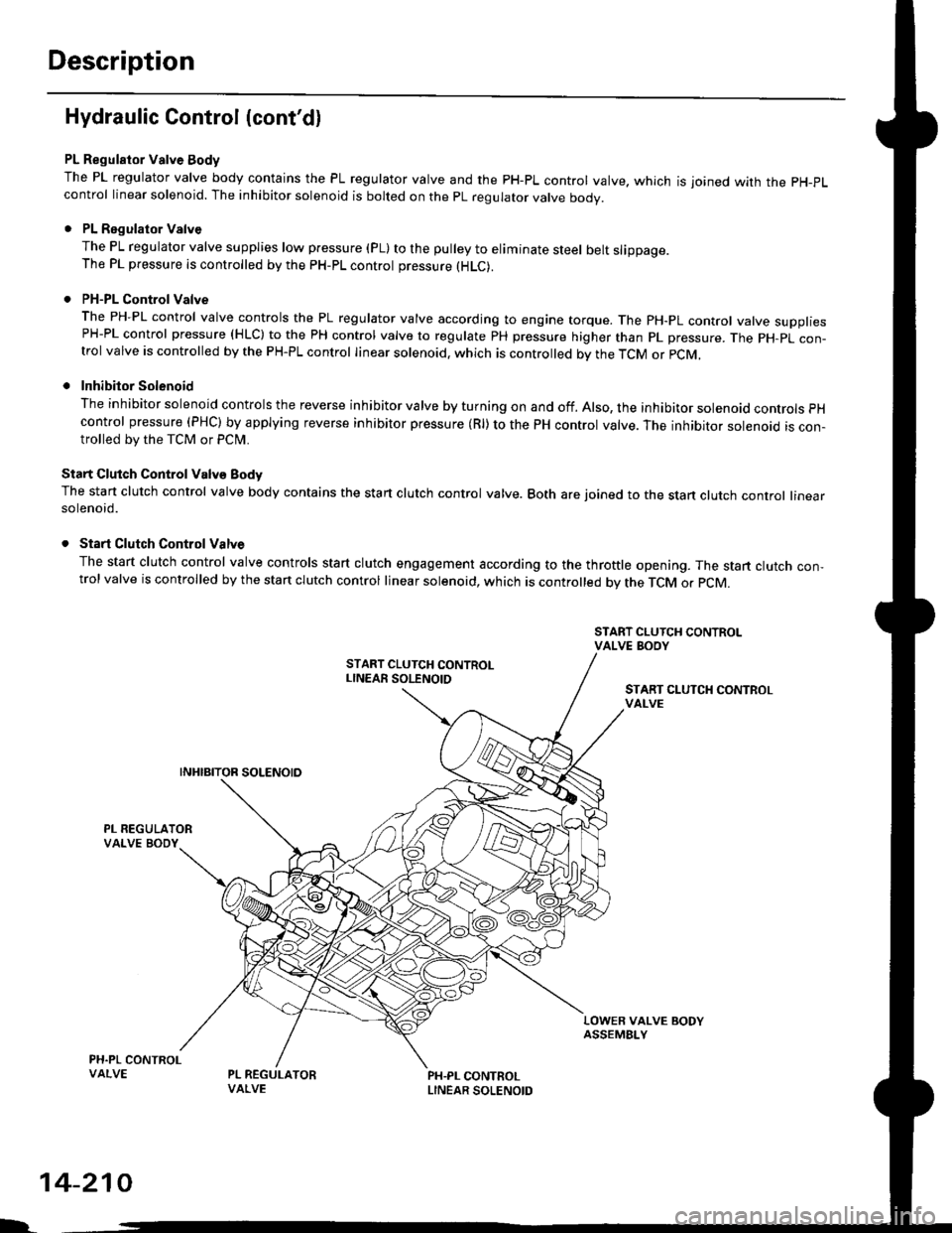
PL Regulator Valve Body
The PL regulator valve body contains the PL regulator valve and the PH-PL control valve. which is joined wirh the pH-pL
control linear solenoid. The inhibitor solenoid is bolted on the pL regulator valve body.
. PL Regulator Valve
The PL regulator valve supplies low p.essure (pL) to the pulley to eliminate steel belt slippage.The PL pressure is controlled by the pH-pL control pressure (HLC).
. PH-PL Control Valve
The PH-PL control valve controls the PL regulator valve according to engine torque. The PH-PL control valve suooliesPH-PL control pressure (HLC) to the PH control valve to regulate PH pressure higher than pL pressure. The pH-pL con-trol valve is controlled by the PH-PL control linear solenoid. which is controlled by the TcM or pcM,
. Inhibitor Solenoid
The inhibitor solenoid controls the reverse inhibitor valve by turning on and off. Also, the inhibitor solenoad controls pH
control pressure (PHC) by applying reverse inhibitor pressure (Rl) to the PH control valve. The inhibitor solenoid is con-trolled by the TCM or Pclvl.
Start Clutch Control Valv€ Body
The start clutch control valve body contains the start clutch control valve. Both are joined to the stan clutch control linearsolenoid.
. Start Clutch Control Valve
The start clutch control valve controls start clutch engagement according to the throttle opening. The start clutch con,trol valve is controlled by the stan clutch control linear solenoid, which is controlled bv the TCM o. pCM.
START CLUTCH CONTROLvAt-vE
LOWER VALVE BODYASSEMBI-Y
PH.PL CONTROLLINEAR SOLENOID
I.
14-210