Page 710 of 2189
Description
Hydraulic Flow (cont'd)
lll Position
The flow of fluid through the torque converter circuit is the same as in E position. The line pressure (1) changes to theline pressure (3) and flows to the l-2 shift valve. The line pressure (3) changes to the line pressure (3,) at the 1-2 shift valveand flows to the servo valve. The servo valve is moved to the right side (Reverse range position) and uncovers the port toallow line pressure (3") to the manual valve as in @ position. The line pressure (3") from the servo valve is Intercepted bythe manual valve. However, hydraulic pressure is not supplied to the clutches, and the power is not transmitted.
NOTE: When used, "|eft" or "right" indicates direction on the hydraulic circuit.
14-32
Page 711 of 2189
\
Lock-up System
Lock-up Clutch
1. Ooeration (clutch onl
with the lock-up clutch on, the fluid in the chamber between the torque converter cover and the lock-up piston is drained
off, and the converter fluid exerts pressure through the piston against the torque converter cover, As a result, the conven-
er turbine is locked to the convefter cover. The effect is to bypass the converter, thereby placing the vehicle in direct drive
LOCK.UP PISTONDAMPER SPRING
The power flows by way ot:
Engine
{
Drive plate
i
Torque converter cover
I
Lock-up piston
Damper spring
I
Turbine
Mainshaft
ODeration {clutch off}
With the lock-up clutch off, the fluid flows in the reverse of "clutch on." As a result, the lock-up piston moves away from
the converter cover, and the torque converter lock-up is releassd.
Engine
t
Drive plate
I
Torque convener cover
{
Pump
I
Turbine
Mainshaft
TOROUECOVER
(cont'd)
COI{VERTER
\
TURBNE
MAINSHAFT
14-33
Page 712 of 2189

Description
Lock-up System (cont'd)
TOROUE CONVERTER
In B.rl position, in 3rd and 4th, and lDl_- position in 3rd.pressurized fluid is drajned from the back of the torqueconverter through a fluid passage. causing the lock-uppiston to be held against the torque convener cover. Asthis takes place, the mainshaft rotates at the same speedas the engine crankshaft, Together with the hydrauliccontrol, the PCM optimized the timing of the lock_upsystem. Under certain conditions, the lock_up clutch isapplied during deceleration, in 3rd and 4th gear.
The lock-up system controls the range of lock_up accord_ing to lock-up control solenoid valves A and B. and thelinear solenoid. When lock-up control solenoid valves Aand B activate, modulator pressure changes. Lock_upcontrol solenoid valves A and B and the linear solenoidare mounted on the outside of the torque converterhousing. and are controlled by the pclvl.
Lock-up Conditions/Lock-up Control Solenoid Valves/Linear Solenoid Pressure
MODULATOR PRESSURE
.-- LINEAR SOLENOID PRESSURE
LOCK.UP CONTROL. VALVE
LOCK.UP CONTROLSOLENOID VALVELock-up
Conditions
Lock-up Control
Solenoid ValveLineal
Solenoid
PressureAB
Lock-up OFFOFFOFFHig h
Lock-up. HalfONDuty operation
OFF - ON
Lock-up. FullONONHigh
Lock-up
during
decelerationONDuty operation
OFF * ONLowTOROUE CONVERTERCHECI( VALVE
RELIEF VAI-VE
LOCK.UP TIMINGVALVE
^ r______rr r cooLER RELTEF VALVE
t'-
14-34
ATF PUMP
Page 713 of 2189
I
TOROUE CONVERTER
No Lock-up
. Lock-up Control Solenoid Valve A: OFF
. Lock-up Control Solenoid Valve B: OFF
. Linear Solenoid Pressure: High
The pressurized fluid regulated by the modulator works
on both ends of the lock-up shift valve. Under this condi-
tion, the pressures working on both ends of the lock-up
shift valve are equal, the lock-up shift valve is moved to
the right side by the tension of the valve spring alone.
The fluid from the ATF pump will flow through the left
side of the lock-up clutch to the torque convener; that is,
the lock-up clutch is in OFF condition.
NOTE: When used, "left" or "right" indicates direction
on the hydraulic circuit.
MOOULATOR PRESSURE
LINEAR SOLENOIO PRESSURE
(cont'd)
LOCK.UP CONTROLSOLENOID VALVE
RELIEF VALVE
LOCK-UP TIMINGVALVE
9 L ] I COOLER RELIEF VALVE
ATF PUMP
14-35
Page 714 of 2189

Description
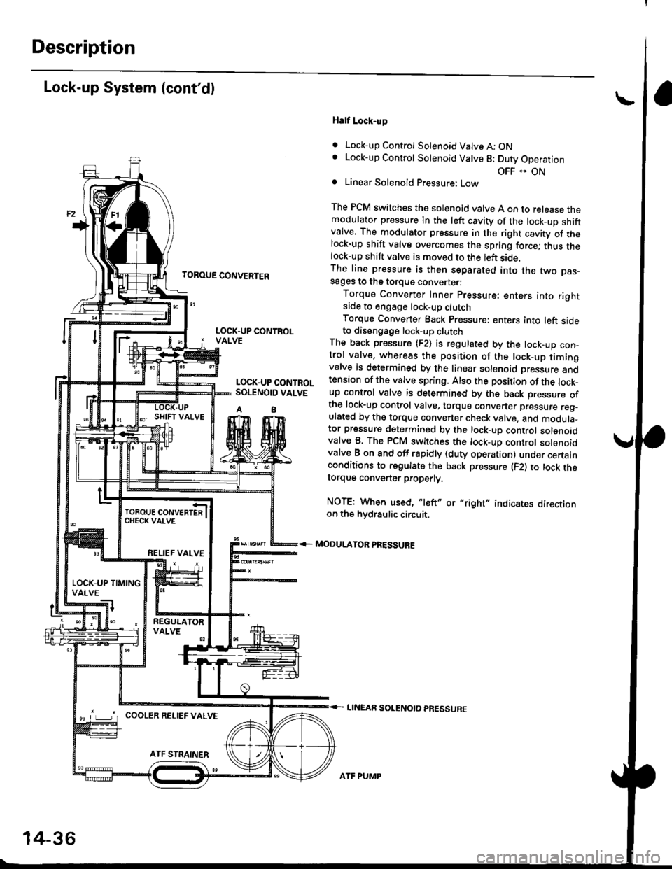
Lock-up System (cont'dl
TOROUE CONVERTER
Half Lock-up
. Lock-up Control Solenoid Valve A: ONLock-up Control Solenoid Valve 8: Duty Operation
OFF - ONLinear Solenoid Pressure: Low
The PCM switches the solenoid valve A on to release themodulator pressure in the left cavity of the lock_up shiftvalve. The modulator pressure in the right cavity of thelock-up shift valve overcomes the spring force; thus thelock-up shift valve is moved to the left side.The line pressure is then separated into the two pas-sages to the torque converter:
Torque Converter Inner pressure: enters into rightsade to engage lock-up clutch
Torque Converter Back pressure: enters into left sideto diseogage lock-up clutchThe back pressure (F2) is regulated by the lock-up con-trol valve, whereas the position of the lock-up timingvalve is determined by the linear solenoid Dressure andtension of the valve spring. Also the position of the lock_up control valve is determined by the back pressure ofthe lock-up control valve, torque converter pressure reg_ulated by the torque converter check valve, and modula_tor pressure determined by the lock-up control solenoidvalve B. The PCM switches the lock-up control solenoidvalve B on and off rapidly {duty operation} under certainconditions to regulate the back pressure (F2) to lock thetorque convener properly.
NOTE: When used, "left" or "right" indicates directionon the hvdraulic circuit.
MODULATOR PRESSURE
LINEAR SOLENOTD PRESSURE
LOCK.UP CONTROLVALVE
LOCK.UP CONTROLSOI.TNOID VALVE
A8
TOROUE CONVERTERCHECK VAI-VE
RELIEF VALVE
LOCK-UP TIMINGVALVE
^ L____J'r cooLER RELTEF valvE
14-36
ATF PUMP
Page 715 of 2189

TOROUE CONVERTER
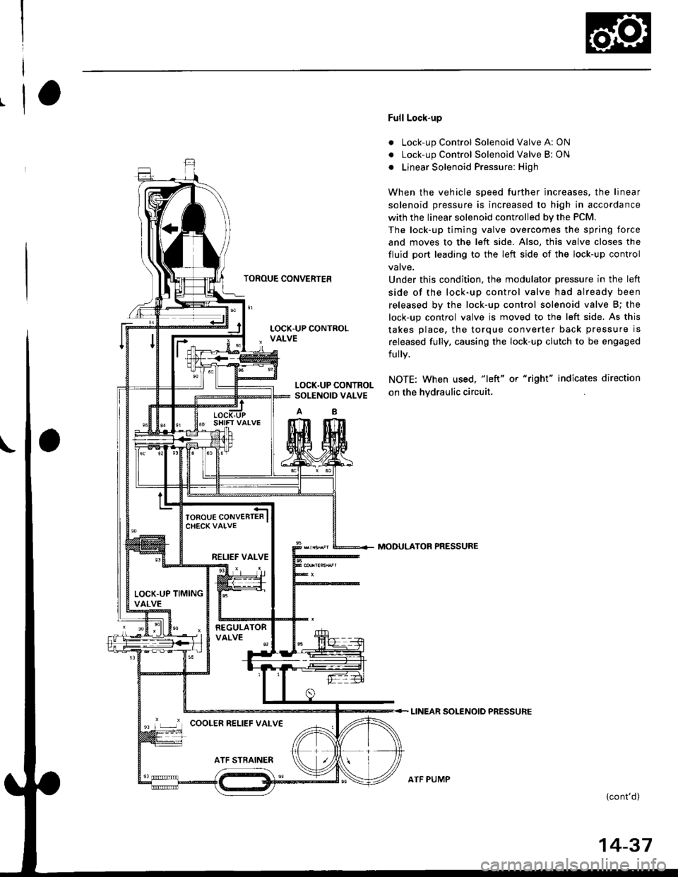
Full Lock-up
. Lock-up Control Solenoid Valve A: ON
. Lock-up Control Solenoid Valve B: ON
o Linear Solenoid Pressure: High
When the vehicle speed further increases. the linear
solenoid pressure is increased to high in accordance
with the linear solenoid controlled bv the PCM.
The lock-up timing valve overcomes the spring force
and moves to the left side. Also, this valve closes the
fluid port leading to the left side of the lock-up control
Under this condition. the modulator pressure in the left
side of the lock-up control valve had already been
released by the lock-up control solenoid valve B; the
lock-up control valve js moved to the left side. As this
takes place, the torque converter back pressure is
released fully. causing the lock-up clutch to be engaged
fully.
NOTE: When used, "|eft" or "right" indicates direction
on the hvdraulic circuit.
MODULATOR PRESSURE
LINEAR SOLENOIO PRESSURE
{cont'd)
LOCK.UP CONTROLSOLENOID VALVE
RELIEF VALVE
LOCK.UP TIMINGVALVE
'r ,-.r' cooLER RELTEF vALvE
ATF PUMP
14-37
Page 789 of 2189
The following symptoms can be caused
by improper repair or assembly
Check these items,on th€^ ltems on thePROBABLE CAUSE DUE TO NOTES ListIMPROPER REPAIR List
Vehicle creeps in N position.R1, R2
Vehicle does not move in &l or Pll position.R4
Transmission locks up in E position.R3, R11
Excessive drag in transmission.R6K,R
Excessive vibration, rpm related.R7
Noise with wheels moving onlY.R5
Main seal pops out.R8
Various shifting problems.R9, RlO
PROBABLE CAUSE DUE TO IMPROPER REPAIR
lmproper clutch clearance.
lmproper gear clearance.
Park lever installed upside down.
one-way {sprag) clutch installed upside down.
Reverse selector hub installed upside down.
ATF pump binding.
Torque converter not fully seated in ATF pump.
Main seal improperly installed.
Springs improperly installed.
Valves improperly installed.
Shift fork bolt not installed.
14-11
Page 790 of 2189

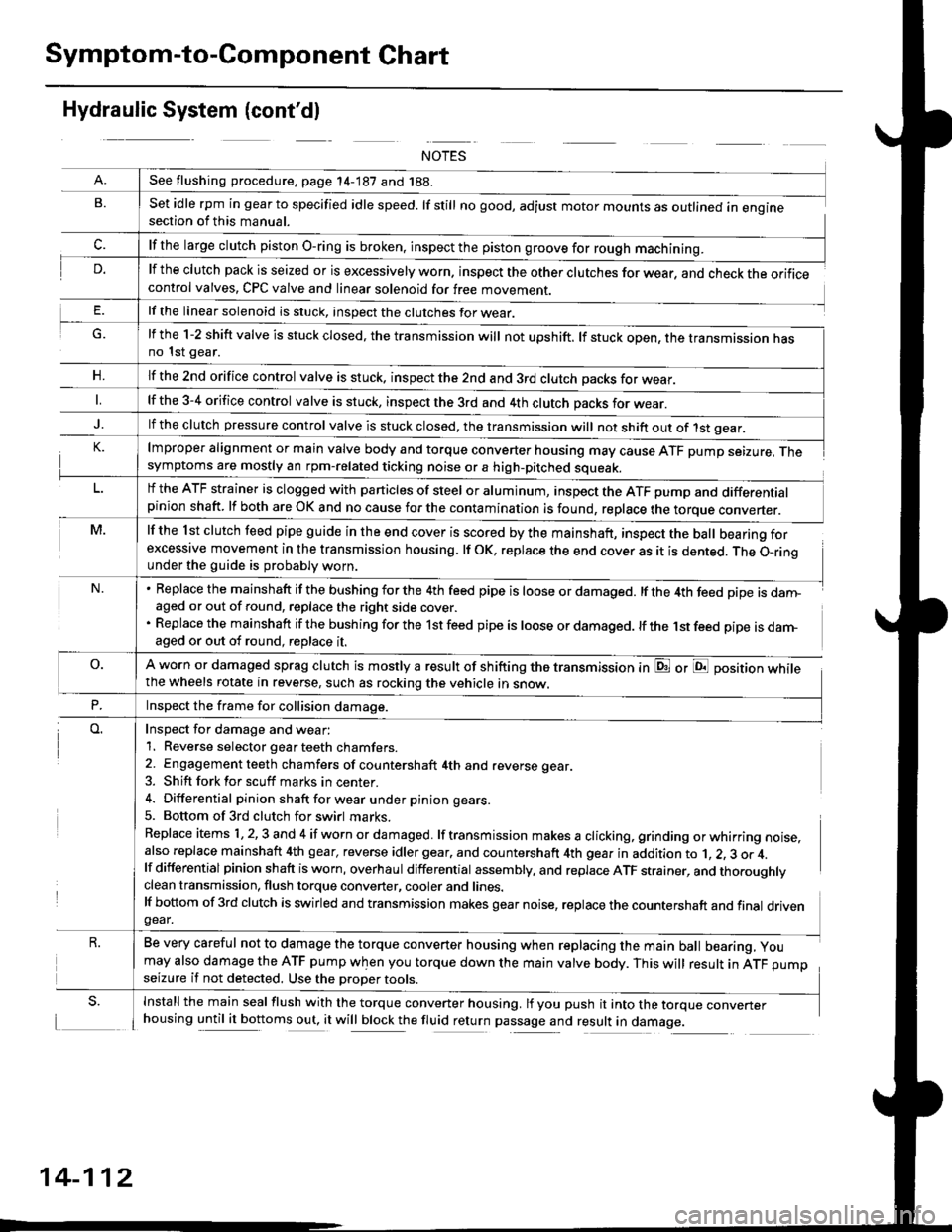
Symptom-to-Component Chart
Hydraulic System (cont'dl
G.
n,
set idle rpm in gear to specified idle speed. lf still no good, adjust motor mounts as outlined in enginesection of this manual.
lf the clutch pack is seized or is excessively worn. inspect the other clutches for wear, and check the orificecontrol valves, CPC valve and linear solenoid for free movement.
lf the linear solenoid is stuck, inspect the clutches for wear.
lmproper alignment or main valve body and torque converter housing may cause ATF pump seizure. Thesymptoms are mostly an rpm-related ticking noise or a high-pitched squeak.
lf the l st clutch feed pipe guide in the end cover is scored by the mainshaft, inspect the ball bearing forexcessive movement in the transmission housing. lf oK, replace the end cover as it is dented. The o-rinounder the guide is probably worn.
Replace the mainshaft if the bushing for the 4th feed pipe is loose or damaged. lf the 4th feed pipe is danFaged or out of round, replace the right side cover.
Replace the mainshaft if the bushing for the 1st feed pipe is loose or damaged. lf the 1st feed pipe is darn-aged or out of round, replace it.
A worn or damaged sprag clutch is mostly a result of shifting the transmission inthe wheels rotate in reverse, such as rocking the vehicle in snow.
or E position while
Inspect for damage and wear:
1. Reverse selector gear teeth chamfers.
2. Engagement teeth chamfers of countershaft 4th and reverse gear.
3. Shift fork for scuff marks in center.
4. Differential pinion shaft for wear u nder pin ion gears.
5. Bottom of 3rd clutch for swirl marks.
Replace items 1,2,3 and 4 if worn or damaged. lf transmission makes a clicking, grinding orwhirring noise,also replace mainshaft 4th gear, reverse idler gear. and countershaft 4th gear in addition to 1, 2, 3 or 4.lf differential pinion shaft is worn, overhaul differential assembly, and replace ATF strainer, and thoroughlyclean transmission, flush torque converter, cooler and lines.lf bottom of 3rd clutch is swirled and transmission makes gear noise, replace the countershaft and final drivengear.
Be very careful not to damage the torque converter housing when replacing the main ball bearing, you
may also damage the ATF pump when you torque down the main valve body. This will result in ATF pumpseizure if not detected. Use the oroper roors.
Install the main seal flush with the torque converter housing. lf you push it into the torque converterhousing until it bottoms out, it will block the fluid return passage and result in damage.
See flushing procedure, page 14-187 and 188.
lf the large clutch piston O-ring is broken, inspect the piston groove for rough machining.
lf the l-2 shift valve is stuck closed, the transmission will not upshift. lf stuck open, the transmission hasno 1st gear.
lf the znd orifice control valve is stuck. inspect the 2nd and 3rd clutch oacks for wear.
lf the 3-4 orifice control valve is stuck, inspect the 3rd and 4th clutch oacks for wear.
lf the clutch pressure control valve is stuck closed, the transmission will not shift out of 1st gear.
lf the ATF strainer is clogged with particles of steel or aluminum, inspect the ATF pump and differentialpinion shaft. lf both are OK and no cause for the contamination is found, replace the torque converter.
Inspect the frame for collision damage.
14-112