Page 1881 of 2189
NOT-E: Fu^se.31 is HO-f-with lgnition Switch in START (tD and clutch pedat depressed orA"iT Gear Selector in PARK (P) or NEUTRAL (N), see Siarting Systeni, page 2i or 21-2.
See Int€oratedControl Jnit.page 70.
UNDER-OASHFUSE/RELAYBOXPHOTO 58
c420
vtEw 53
PGM-FIMAINRELAY
vtEW 18
|- flrn*',
""-"'l
""^"*l *L
I
016Y5/D16Y8 D16,
;-ensnewrh",r-t :--*f 3l3yi:131ffi,-'' ---
I H;[h- N
i ii jt
lilT:{xsl I
ffifi:iil:"'"" il
-UTtl
i ryffi$il: i i ffifrffi ,,1 _,_:_____r,"*,
,A124 , , A14A, A13A ' 416A C6APOWERTRAIN, , ,^lAcy) (iAcvP) (rAcv N) | crnt $rs): I rAurr'arve , i r--.-, : Fuel pump control Start input ! :rNGtNFi , nt;*Y:l"" , i r--r I Fuel pump conkol Stan input | ;'NG|NElr 'uv"nv' : , IAC valve controt ' ICONTROL\I , I MODULE
t'----- ':------------i l(PcMorEcM)
I t'�;[?,i?"*L------ ---J
(cont'd)
---l-lf -----=-------------=--:
i
"au*", IzI
23-1
Page 1896 of 2189
NOTE: Fuse 3l is HOT with lgnition Switch in START (lll) and clutch pedal depressed or
A'/T Gear Selector in PARK (P) or NEUTRAL (N), see Starting System, page 21 or 21-2.
FUSE 31SIAilEfi SIGT{AL7.fi
UNDER.DASHFUSE/RELAYBOXPHOTO 58See ldeoratodControl Unit,page 70.
1110c420
vtEv,/ 53
PGM-FIMAINRELAY
vlEW 18
-:f]'" l;;;,b"YEUG8N
I
vtEw 40
i fli,i{ry;g:l lr R;::i8i3ll:13rffi:-''
'r
I H[f#'-
il |r'ru*
ljT-.i|ff
| - Friofo 1id | | I | Plioio {- n, 1 Y LJirJ-J plroio 4s tot6v7, I I G552'lt:i:PHotosa
I [ :: ! 'l r------' er-xl iiar-xfi onrl
i*"1 l:"'l I :
: I i: I I :
iazsA ii eoA ers|' , ltol lcql.I POWERTRAIN,a1F--X-lo"i"r t, "u*t : (FLF)
! , lAcvatve I i rq;.,.-...,; : Fu€r pump controt s"liii'p", ! EHc,le:;w, ruEr PqrrPlJtrIulI , connot :; IAC vatve controt , ! CONTROL
(cont'd)
24-1
Page 1921 of 2189
i - '99100 016Y7/D16Y8 with A"/T -
Cruiseconrolsgnal
i8s) i
iil
POWERTRAINCONTROLMODULE(PcM)
* = '96-'98: All models'99100: D16Y5 with M/T, 01685
-----i-----.lcRU|sE
| ; Cruise control ' I CONTROL
signaloutput ' |oNirI PHATO 55
I oisengage input vehicle speed input ' vtEw 13
.--------;---- ---J
See Vehicle
Sensor rySS)
See GfoundDigtribution,page 14-5.
I
J
"{
,--r-s=-.
CLUTCHswtTcHOpen withclutch pedaloepresseo.
A/T GEARPOSITIONswtTcH
L- ----
ALU,ryVHT
3x
ct30Cferminals11.13)PHATO E3vlEw 52See GrolndDlslribution,page 14-6.
IY
ll
L__l#: G401
lI:::1" I
I output I
VEHICLESPEEDSENSOR(vss)
O-a
34-3
Page 1922 of 2189

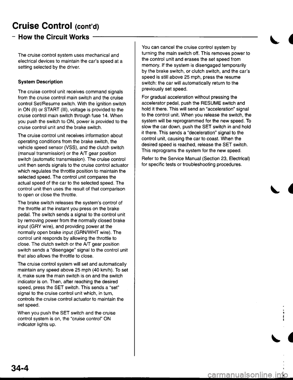
Gruise Control (cont'd)
- How the Circuit Works
The cruise control system uses mechanical and
electrical devices to maintain the car's sDeed at a
setting selected by the driver.
System Description
The cruise control unit receives command signals
from the crurse control main switch and the cruise
control SeVResume switch. With the ignition switch
in ON (ll) or START (lll), voltage is provided to the
cruise control main switch through fuse 14. When
you push the switch to ON, power is provided to the
cruise control unit and the brake switch.
The cruise control unit receives information about
operating conditions from the brake switch, the
vehicle speed sensor (VSS), and the clutch switch
(manual transmission) or the A,/T gear position
switch (automatic transmission). The cruise control
unit then sends signals to the cruise control actuator
which regulates the throttle position to maintain the
selected speed. The conlrol unit compares the
actual speed of the car to the selected speed. The
control unit then uses the result of that comoarison
to open or close the throttle.
The brake switch releases the system's control of
the throttle at the instant you press on the brake
pedal. The switch sends a signal to the control unit
by removing power from the normally closed brake
input (GRY wire), and providing power at the
normally open brake input (GRN/vVHT wire). The
control unit responds by allowing the throttle to
close. The clutch switch or the A,/T gear position
switch sends a "disengage" signal to the control unit
that also allows the throttle to close.
The cruise control system will set and automatically
maintain any speed above 25 mph (40 km/h). To set
it, make sure the main switch is on and the switch
indicator is on. Then, after reaching the desired
speed, press the SET switch. This sends a "set"
signal to the cruise control unit which, in turn,
controls the cruise control actuator to maintain the
set speed.
When you push the SET switch and the cruise
control system is on, the "cruise control" ON
indicator lights up.
34-4
(
You can cancel the cruise control system by
turning the main switch off . This removes power to
the control unit and erases the set speed from
memory. lf the system is disengaged temporarily
by the brake switch, or clutch switch, and the car's
speed is still above 25 mph, press the resume
switch: the car will automatically return to the
previously set speed.
For gradual acceleration without pressing the
accelerator pedal, push the RESUME switch and
hold it there. This will send an "acceleration" signal
to the control unit. When you release the switch, the
system will be reprogrammed for the new speed. To
slow the car down. oush the SET switch in and hold
it there. This sends a "deceleration" signal to the
control unit, causing the car to coast. When the
desired speed is reached, release the SET switch.
This reprograms the system tor the new speed.
Refer to the Service Manual (Section 23, Electrical)
tor specific tests or troubleshooting procedures.
(
a
Page 1928 of 2189
aI
I coNrRoL
EcM EcM lllg?.Y.ERelernce control data control I H;,."voftase output ff.'nour a;i:;Y"*- lug'L - - - - JS- - - - - J't3'- - - iA25Y CgY C30Y
lL
I 1=,
-"'"'"1 ""1 "-l
rRANsM,ss,oN
,r, ,[ ", I ". I
"oou".-o'"[3fl!
NnEF) O[,!A) OMB)Beference ECM control ECM control D..r.i.^vollage data input data output ;;ii; vI
t
swrtch
CVT transmrssion conlrol solenoids signal DTC CVT grounds
j input outputlPcrr /pcl).t HLC LS I iHLC LS+l {SC LS-) tSC LS-) (SH Ls-i ISH LS-l ISOL INH' THBRK SWt {O'AG Hr {LGli {LGl) lPclr tpclj :
{*n*
:".,1 :"::.1 i.lnu+
',sk,-[lr*:[l*':t'
*?:?' """",.0-fr;rt.o,1^,, *'ig"#"t I""-t cw i
-"' iiio lr.'t l
lsel$tfis'! I !
izf-"{}Y
f,====i iiu:'" !
I ii,l;?:' i
lt r---L
4 9::1",- (cont'd)
39-s
PH.PL START SHIFTCONTFOL CLUTCH COITTROLLINEAR CONTROL LINEARSOLENOID LINEAR SOLENOIDSOL:NOID
Page 1936 of 2189
?uTi'i'------lUNDER.OASHFUSE/RELAYBOX
UNDER-HOODFUSE/RELAYBOXfI,€! PtfiP
f#rntt)See PowerDistribution,
iT;;*-l
rr:_i
y;lftr,.:{'
page 10-2.tJ---------J" Y 3,,t"?:"""""T
[']':.
i-?;;ffi;
i_f___
PGM-FIMAINRELAY
;;II
;;;I
c't0'l
vtEw 28
TI
":{
c130Oerminals l4-17)
vlEw 52
I . (rGP1) i 1rGP2) - I
Power input
..���������������
SeePGM,FI
POWER.TRAINCONTROLMODULE(PcM)PHO|O 86
(cont'd)
\!
CW hansm|ssion_ control solonoids Ground I
t (HLC LS-) THLCLS+) (SCLS-) (SCLS'I iSH LS I rSHLS+j ISOLINHI lPGr) (PO2) (LG1) rLG2r IL-------i:---- ---------J
-T1
Tj
:1 ;
lruffil
GRNBLII
cl16(Terminals8-14)
vlEW 39BLK
CVTTRANS.MISSIONSOLENOID
See GroundDistribution,page 14-2.
BRN/BLK
PH.PL START SHtF'CONTROL CLUTCH CONTNOLUN€AR CONTNOL LINEARSOLENOID UI{EAR SOLENOIDsoLEltotD
:_-:_-___1
-t
1-! |
Ti11:a__J
BRN/BLK
39-13
Page 1954 of 2189
A/C Compressor Controls
- AllModels
cc5)M7
BLU/RED
?
\a
@
&cCOMPRESSORCLUTCHRELAYPHOfO 10
a
! ,acc, : POWERTRATN! arn.^-^,o..^, I or ENGINE
! ii i"i-iiii"v i.,ii.r | fi 3$18.
I A/C request ! (pCM or ECM)I (ACSJ a pHOrO a6L------J vtEw 70
REO
BEO
1
RED
BLU/FEO
2
BLU/FEO
ct31
:"1'!i'------;
Fi:rz, a ='e6-'s8: A|| moders except D1685vtEw 21 '99100: D16Y5 with l\illT'* = 96-'98: All models
ir'iio ," 99. 00: Dt6y5 wth t\4/t Dl6Bb
atcPRESSUREswtTcH
c752
c1
".,n""t 1(
".r-".rf, "tA% "
"."-:,fi tfr,]4.
v
To facing page ('96''98 models)or page 62'2 ( 99-'00 models).
-Yl
-t---------Jc353
c2'14
vtEW21
c209
A,/CCOMPRESSORCLUTCH
COMPRESSORTHERMALPROTECTOR
UNDER-HOODFUSE/RELAYBOXf-T-*-'.T'---l H53.',EPA?' i-l-------
i iflH* !F,?r",, i f6F"'.i:.",",
| tsBi":J;"#il ! a T| | oaoe 1o-9. ! I I See PowerL_J1_j:_-_j ! H Distriburion.e Y c42o i I
pase 1o-1.
***
f ifi"l'
^ see power ! |
62
!(on bracket)
Page 1957 of 2189

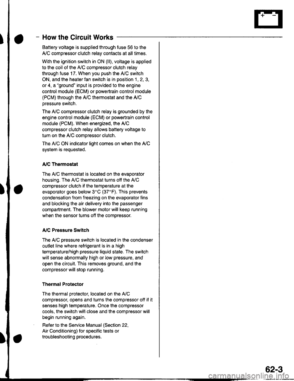
- How the Circuit Works
Battery voltage is supplied through tuse 56 to the
A,/C compressor clutch r€lay contacts at all times.
With the ignition switch in ON (ll), vollage is applied
to the coil of the A,/C compressor clutch relay
through fuse 17. When you push the A,/C switch
ON, and the heater fan switch is in position | , 2, 3,
or 4, a "ground" input is provided to the engine
control module (ECM) or powertrain control module
(PCM) through the l'lC thermostat and the l'lC
pressure switch.
The A,/C compressor clutch relay is grounded by the
engine control module (ECM) or powertrain control
module (PCM). When energized, the A'lC
compressor clutch relay allows battery voltage to
turn on the A,/C comDressor clutch.
The A,/C ON indicator light comes on when the A,/C
system is requested.
A,/C Thermostat
The A'lC thermostat is located on the evaoorator
housing. The A,/C thermostat turns off the A,/C
compressor clutch if the temperature at the
evaporator goes below 3'C (37'F). This prevents
condensation from freezing on the evaporator fins
and blocking the air delivery into the passenger
compartment. The blower motor will keep running
when the sensor turns off the comDressor.
A,/C Pressure Switch
The fuC oressure switch is located in the condenser
outlet line where refrigerant is in a high
temperature/high pressure liquid state. The switch
will sense abnormally high or low pressure, and
open the circuit. This removes ground, and the
compressor will stop running.
Thermal Protectot
The thermal protector, located on the A,/C
compressor, opens and turns the compressor off if it
senses high temperature. Once the compressor
cools, the switch will close and the compressor will
begin running again.
Refer to the Service Manual (Section 22,
Air Conditioning) for specific tests or
troubleshooting procedures.
62-3